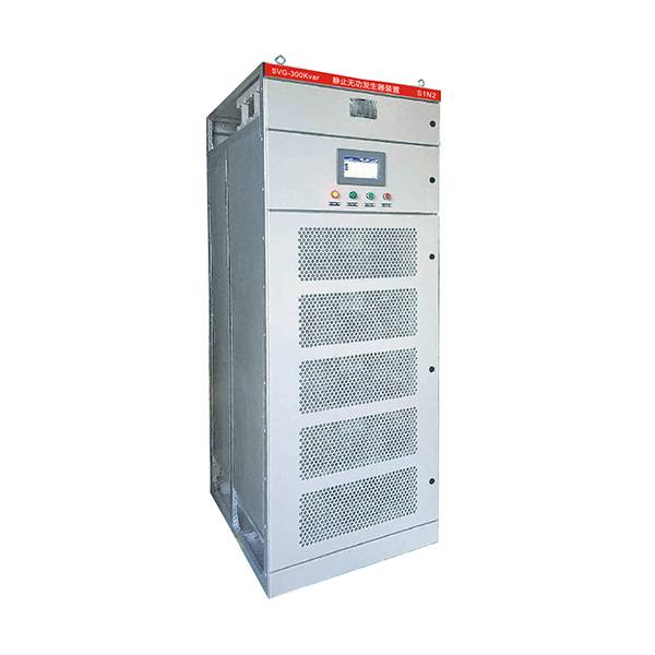
A reactive power compensation device, also known as a power factor correction device, is indispensable in a power system. Its main function is to improve the power factor of the supply and distribution system, thereby increasing the utilization efficiency of transmission and substation equipment, improving energy efficiency, and reducing electricity costs. In addition, installing dynamic reactive power compensation devices at appropriate locations in long-distance transmission lines can improve the stability of the transmission system, increase transmission capacity, and stabilize the voltage at the receiving end and the grid.Reactive power compensation devices have gone through several stages of development. In the early days, synchronous phase advancers were the typical representatives, but they were gradually phased out due to their large size and high cost. The second method was using parallel capacitors, which had the main advantages of low cost and easy installation and use. However, this method requires addressing issues such as harmonics and other power quality problems that may exist in the system, and the use of pure capacitors has become less common.Currently, the series capacitor compensation device is a widely used method to improve power factor. When the load of the user system is continuous production and the load change rate is not high, it is generally recommended to use fixed compensation mode with capacitors (FC). Alternatively, an automatic compensation mode controlled by contactors and stepwise switching can be used, which is suitable for both medium and low voltage supply and distribution systems.For fast compensation in cases of rapid load changes or impact loads, such as in the rubber industry’s mixing machines, where the demand for reactive power changes rapidly, the conventional reactive power automatic compensation systems, which use capacitors, have limitations. When the capacitors are disconnected from the power grid, there is residual voltage between the two poles of the capacitor. The magnitude of the residual voltage cannot be predicted and requires 1-3 minutes of discharge time. Therefore, the interval between reconnection to the power grid needs to wait until the residual voltage is reduced to below 50V, resulting in a lack of quick response. Additionally, due to the presence of a large amount of harmonics in the system, LC-tuned filtering compensation devices composed of capacitors and reactors require large capacity to ensure the safety of the capacitors, but they can also lead to overcompensation and cause the system to become capacitive.Thus, the static var compensator (SVC) was born. The typical representative of SVC is composed of Thyristor Controlled Reactor (TCR) and fixed capacitor (FC). The important feature of the static var compensator is its ability to continuously adjust the reactive power of the compensation device by controlling the triggering delay angle of the thyristors in the TCR. SVC is mainly applied in medium to high voltage distribution systems, and it is particularly suitable for scenarios with large load capacity, severe harmonic problems, impact loads, and high load change rates, such as steel mills, rubber industries, non-ferrous metallurgy, metal processing, and high-speed rails.With the development of power electronics technology, particularly the emergence of IGBT devices and advancements in control technology, another type of reactive power compensation device has emerged that is different from the traditional capacitors and reactors-based devices. This is the Static Var Generator (SVG), which utilizes PWM (Pulse Width Modulation) control technology to generate or absorb reactive power. SVG does not require impedance calculation of the system when not in use, as it uses bridge inverter circuits with multi-level or PWM technology. Furthermore, compared to SVC, SVG has the advantages of a smaller size, faster continuous and dynamic smoothing of reactive power, and the ability to compensate both inductive and capacitive power.
Post time: Aug-24-2023