Zhejiang Hongyan Electric Co., Ltd.















ENGINEERED SOLUTION
Steel & Metallurgy Power Quality Solutions
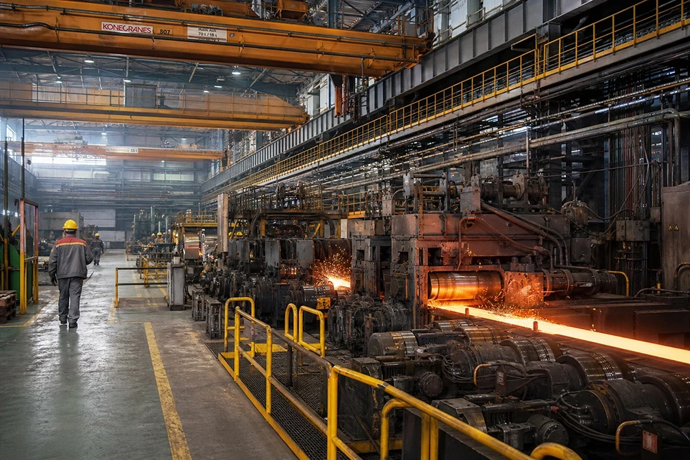
Power factor correction, harmonic mitigation and voltage support for electric arc furnaces, rolling mills, cranes and high-load metallurgical production lines.
 HYSVGC Series Hybrid Static Var Dynamic Compensation Device
 HYSVG Static Var Generator (SVG)
 HYSVG Pole-Mounted Outdoor Three-Phase Imbalance Correction Device
 HY-HPD Series Harmonic Protection Device
 HYSVG Series High Voltage Dynamic Reactive Power Compensation Device
 HYAPF Series Active Power Filter
 HYTSF Series Low-Voltage Dynamic Filtering & Compensation Device
 HYMSVC Series High-Voltage Dynamic Filtering and Compensation Device
 HYLX Zero-Sequence Current Absorber
 HYFCKRL Series Ferroalloy Submerged Arc Furnace Harmonic Filtering & Reactive Compensation System
 HYFC Series Low-Voltage Static Passive Harmonic Filter & Compensation Device
 HYFC-ZP Series Passive Harmonic Filter & Energy-Saving Compensation Device for Intermediate-Frequency Furnaces
 HYFC-ZJ Series Passive Harmonic Filter & Reactive Compensation Device for Rolling Mills
 HYFC-BP Series Passive Harmonic Filter for VFD Systems
 HYTSC High-Voltage Dynamic Reactive Power Compensation System
 HYTBBT Series On-load Voltage & Reactive Power Regulation System
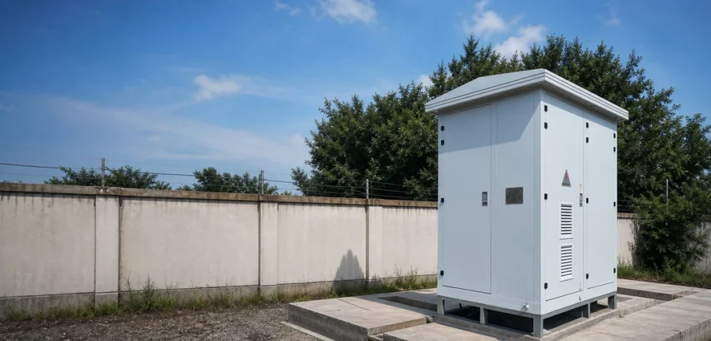
 HYTBB Series Medium & High Voltage Reactive Power Compensation System – Outdoor Box Type
 HYTBB Series Medium & High Voltage Reactive Power Compensation System – Indoor Frame Type
 HYTBB Medium and High Voltage Reactive Power Compensation Cabinet
 HYTBBW Series Pole-Mounted High Voltage Reactive Power Compensation Device
 HYSVC Series High Voltage Dynamic Reactive Power Compensation and Filtering Device
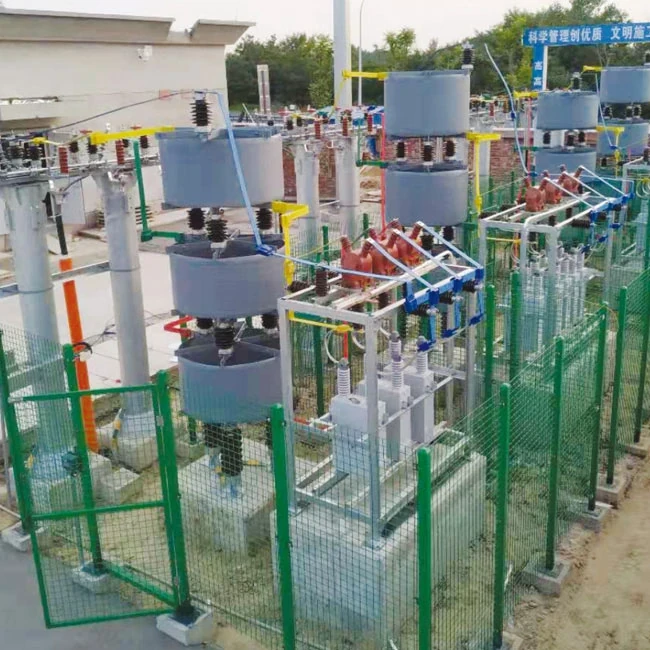
 HYTBB Series High-Voltage Reactive Power Compensation Device – Outdoor Frame Type
| Code | Meaning |
|---|---|
| P | Reactance |
| H | Filter circuit |
| W | Outdoor frame type |
| X | Outdoor cabinet type / Indoor cabinet type |
| K | Open-delta overvoltage protection |
| C | Phase-voltage differential protection |
| L | Neutral-point unbalanced current protection |
| A | Single-star connection |
| B | Double-star connection |
| □ | Single capacitor unit capacity (kvar) |
| □ | Rated capacity of the device (kvar) |
| 10 | System voltage (kV) |
| Z | Device type: automatic switching |
| L | Filter compensation |
| X | Fixed compensation |
| T | Voltage-regulating compensation |
| W | Line type |
| Y | Reactive compensation unit |
| /P6 | Manufacturer code |
| Parameter | Specification |
|---|---|
| System voltage | 6–35 kV |
| Rated frequency | 50–60 Hz |
| Rated capacity | • 150–10,000 kvar (10 kV and below)• 600–20,000 kvar (35 kV) |