
 Zhejiang Hongyan Electric Co., Ltd.





































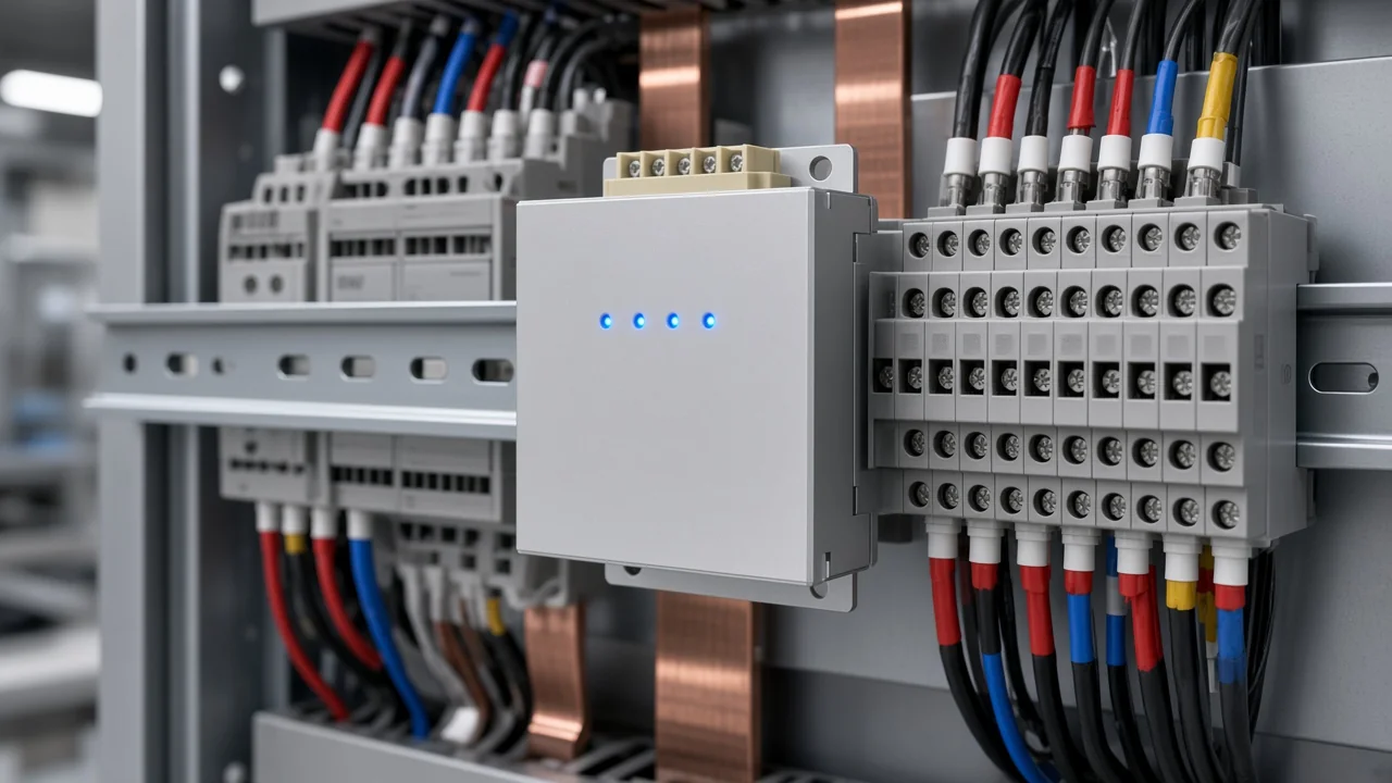
Correct active harmonic filter industrial installation puts the unit on the plant bus that feeds the nonlinear loads, lands CTs with the right location and polarity, grounds and cools the enclosure, and enables compensation only after a written checklist. Get the sensing and grounding wrong and the filter can amplify harmonics or trip before it helps. This article maps that plant sequence for AHF/APF-class equipment and shows when a compact harmonic protection device fits a control cabinet versus when a compensating-current injector belongs on the bus.
For measured-current rating and CT specification design, see the sibling active harmonic filter design article. Series overview lives on the Active Power Filter Series hub. Related install language also covers active power filter installation, CT placement active harmonic filter practice, and active harmonic filter commissioning order.
Place the Filter on the Plant Bus That Feeds the Distortion
Put the filter on the feeder or MCC plant bus that supplies the VFD and rectifier cluster you intend to correct—not on a quiet remote board that barely sees the nonlinear loads.
Installation position changes how much compensating current you need to meet a distortion goal. Academic work on APF placement treats the bus that finishes the job with the smallest injection current as the better location once distortion targets are met (IOP study on optimal APF installation point).
In a plant that usually means the extrusion, HVAC, or printing feeder that carries the worst drive current. Field language matches that map: active filters are often chosen where several nonlinear loads turn on and off on a shared bus (r/ElectricalEngineering discussion). Location is an install decision here; ampere rating from a measurement log stays with the design sibling.
Wire CTs for Location, Polarity, and a Never-Open Secondary
Match the filter’s CT-location setting to where each current transformer physically sits, face H1/P1 toward the source, and keep every secondary shorted until the filter terminals are landed.
Industrial AHF cabinets support source-side (closed-loop) or load-side (open-loop) CT placement. Source-side CTs sit upstream of the filter and see the improved grid current. Load-side CTs sit toward the nonlinear loads and see load current without the filter contribution.
The HMI or setup parameter must agree with that physical choice. A LINE setting with LOAD wiring—or the reverse—feeds the controller the wrong story.
| CT arrangement | What the CTs see | Install note |
|---|---|---|
| Source-side / closed loop | Grid current including filter injection | Common when parallel modules share one CT set |
| Load-side / open loop | Load current only | Must match the filter’s load-side setting |
| 3P3W | Often two CTs on two phases | Third phase inferred by the controller |
| 3P4W or line-neutral loads | Three phase CTs | Add the third CT when the neutral path matters |
Polarity is not cosmetic. H1 or P1 faces the source; S1/S2 (or X1/X2) land in matching order. Reversed polarity or swapped phases is a known way for an active filter to strengthen harmonics instead of cancelling them.
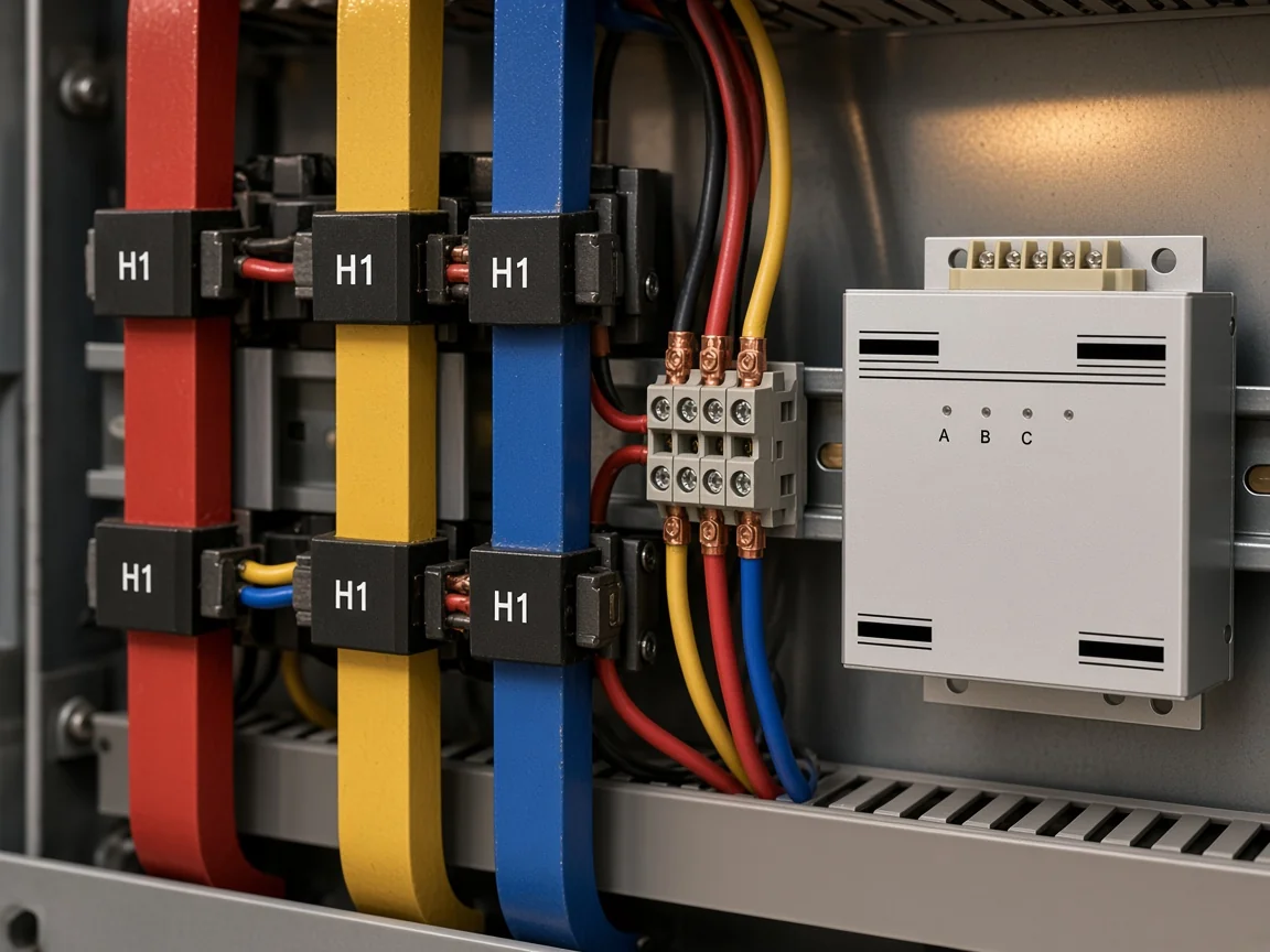
From the field: Never leave a CT secondary open while primary current can flow. Crews who “run the cable through today and land S1/S2 tomorrow” create a shock and insulation hazard—keep shorting links on until the filter terminals are complete (Physics Forums on open CT secondaries; shorting practice discussion).
CT ratio and accuracy-class selection for a design package belong in the design article. This section only locks the install behaviors that decide whether the rating you already bought can sense the bus at all.
Keep Power Conductors and CT Cables on Separate Paths
Route power feeders and CT/control pairs apart so the sensing path stays usable.
Power cables take a short path from the conduit entry to the filter terminals and the PE stud. CT secondaries belong in their own shielded pair or grounded metal conduit—not twisted through the same power trough as the phase leads.
Splices on CT leads should be crimped or soldered, not taped twists that open under vibration. Dedicated sensing also means the AHF CTs should not share a secondary with unrelated metering if the manufacturer forbids it. When another meter needs current, use a separate transformer.
Ground the Enclosure as a Dedicated Low-Impedance Path
Land a dedicated protective earth conductor on the chassis ground terminal and keep high-frequency bonds short—do not treat conduit or painted mounting rails as the ground.
Active filter cabinets carry leakage current and switching noise. Industrial install practice calls for a real PE conductor, short high-strand bonds where HF paths matter, and clean metal-to-metal contact after paint is removed at the bond point.
Mounting the back panel to painted steel, or hoping the conduit locknut is enough, fails ordinary install checklists even when the phase wires look perfect. Keep ground leads short and flat where the manual asks for HF bonding.
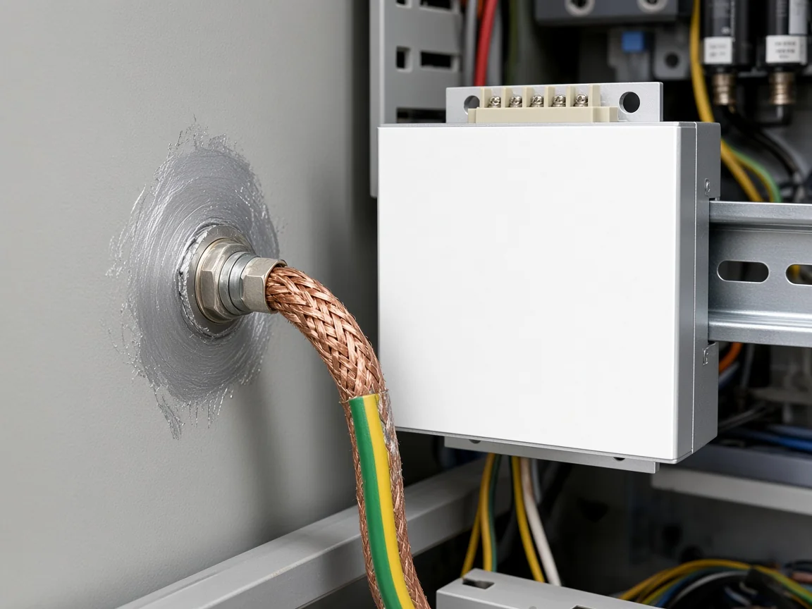
The same discipline applies when a compact harmonic protection module shares a control cabinet with PLCs: the DIN-rail device still needs its PE path, not a floating chassis.
Leave Cooling Airflow and Service Access in the Cabinet
Leave the manufacturer’s intake and exhaust paths open, and keep the door swing and terminal access usable for service.
AHF injector cabinets move air through bottom-to-top or front-to-rear paths. Blocking the intake with cable trays, stacking modules without the allowed vertical gap, or parking the unit in a sealed dead corner is an install error, not a “later HVAC” problem.
Compact protection modules such as a rail-mounted harmonic protection device still need clearance from heat sources and room to land conductors without pinching insulation. Accessibility matters as much as airflow.
If a technician cannot reach CT shorting blocks or PE studs without removing adjacent gear, commissioning becomes guesswork. Site prep is simple: clean, dry, ventilated, and reachable—then follow the nameplate ambient notes for the specific cabinet you received.
Run a Commissioning Checklist Before Enabling Compensation
Prove mechanical integrity, CT location and polarity, grounds, and on-screen measurements with compensation still off—then enable filtering. Use a written commissioning checklist before the first enable.
| Step | Check | Pass look |
|---|---|---|
| 1 | Visual and mechanical | No shipping damage; fasteners torque-checked; debris cleared |
| 2 | Power and PE | L1/L2/L3/(N) and dedicated earth landed per drawing |
| 3 | CT location setting | HMI source/load matches physical CT placement |
| 4 | CT polarity and shorts | H1 to source; shorting links removed only after secondaries land |
| 5 | Phase correspondence | Displayed currents and power sign look sane with plant load |
| 6 | Enable compensation | Turn filtering on only after steps 1–5 pass |

OEM commissioning sheets also walk visual inspection, ambient within the product’s working range, CT ratio notes, removal of temporary jumper bars, and on-screen parameter confirmation before the unit is trusted. Copy the structure, not another brand’s Newton-meter table, onto your drawing package.
If signed power looks inverted or THD rises when the filter enables, stop. Recheck CT location, polarity, and phase order before raising a gain or priority setting.
Select HY-HPD When the Install Protects Control Electronics
Recommend the HY-HPD Series Harmonic Protection Device when the industrial install job is protecting PLC platforms, DCS systems, sensors, wireless equipment, and CT systems inside a harmonic-rich automation cabinet that needs compact rail or screw mounting.
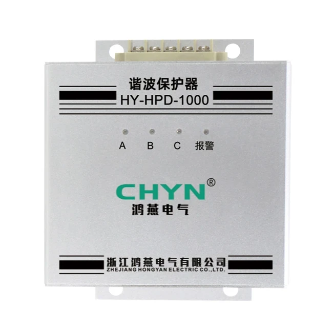
HY-HPD is published for three-phase Y or delta connection and a 250 V rated phase voltage. The live product page lists clamping voltage ≤1000 V and surge current ≤1000 A (8/20 μs).
It also lists an effective harmonic absorption range of 2 kHz–10 MHz, dimensions of 130 × 90 × 75 mm, rail-mounted or screw-mounted installation, and an operating range of −40 °C to +85 °C. The page states compliance with IEC61000-4-5 and IEC60939-1-2.
That package fits a control-cabinet protection install—not a bus-level ampere injector. When the plant instead needs a pure compensating-current injector cabinet on the LV bus, use the HYAPF Series Active Power Filter, which measures load current and injects an equal, opposite harmonic current.
Do not treat HY-HPD as a substitute for that injector job, and do not treat HYAPF as a DIN-rail PLC protector.
FAQ
Where should an active harmonic filter be installed in an industrial plant?
On the feeder or MCC bus that supplies the dominant nonlinear loads you intend to correct. Placement affects how much injection current is needed to meet a distortion goal; a quiet remote board is usually the wrong install.
Should AHF current transformers be on the load side or the source side?
Either arrangement can work if the filter’s CT-location setting matches the physical wiring. Source-side CTs sit upstream of the filter; load-side CTs sit toward the loads. Parallel systems often require source-side CTs—follow the cabinet drawing.
Why does CT polarity matter on an active harmonic filter?
Wrong H1/P1 direction or swapped S1/S2 pairs can make the unit inject in the wrong sense and strengthen harmonics. Face H1 toward the source and keep phase order consistent with the terminals.
Can CT secondaries stay open during installation?
No. An open CT secondary with primary current present can produce dangerous voltage. Keep shorting links installed until the filter CT terminals are landed, then remove them per the commissioning plan.
How should an active harmonic filter cabinet be grounded?
Use a dedicated PE conductor to the chassis ground terminal with clean metal contact. Do not rely on conduit alone or painted mounting surfaces as the safety ground.
How much clearance and ventilation does an AHF need?
Leave the manufacturer’s airflow paths open and keep service access to CT and PE terminals. Do not invent millimeter clearances beyond the nameplate and manual for the unit you received.
What belongs on a pre-energization checklist?
Visual integrity, power and PE landings, CT location setting versus physical placement, polarity and shorting-link removal, sane on-screen currents/power sign, then enable compensation.
When is HY-HPD the right install fit instead of an injector cabinet?
When the job is protecting PLC/DCS/sensors/CT systems in a compact automation cabinet under harmonic stress. For bus-level compensating-current injection, select HYAPF instead.
References
- Determination of Optimal Installation Point of APF Based on Selective Harmonic Compensation (IOP Conf. Series)
- Danger of open-circuited current transformer (Physics Forums)
- Are integrated CTs any different from CTs in clamp meters? (Physics Forums)
- Components in passive and active harmonic filters (r/ElectricalEngineering)