
 Zhejiang Hongyan Electric Co., Ltd.
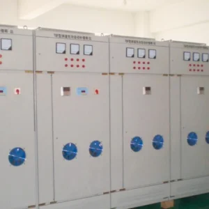
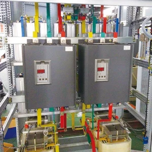
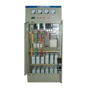
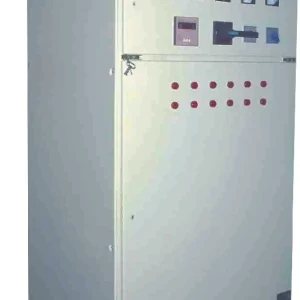
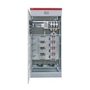
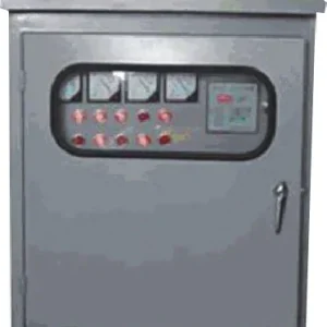
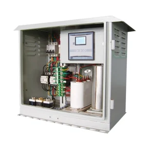
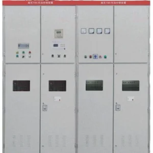
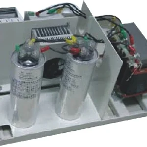
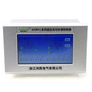
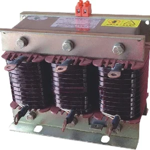
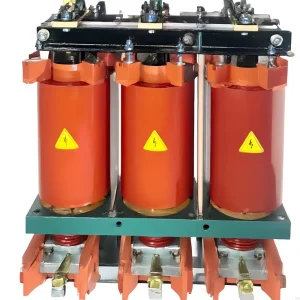
Capacitor bank capacitance loss should be confirmed by repeatable capacitance measurements and a review of the bank's actual circuit. A lower kvar reading alone does not prove dielectric degradation: reduced voltage, an unavailable step, an open fuse, measurement error or a different operating state can produce similar symptoms. Establish what was connected, normalize comparable output for voltage and frequency where appropriate, and then investigate the identified units under an approved isolated test procedure.
This guide addresses declining output and the evidence needed for a repair decision. It complements the general capacitor bank maintenance program. It does not replace the supplied capacitor's test instructions or create a universal percentage at which every capacitor must be replaced.
Distinguish a missing branch from a changed capacitor
Start with the bank drawing and operating log. Count the steps actually energized during the observation, rather than relying on the installed nameplate total. Check controller commands against available switching and protection indications. A commanded step can remain unavailable, and a bank with fewer connected branches will deliver less reactive output even if the remaining capacitors are healthy.
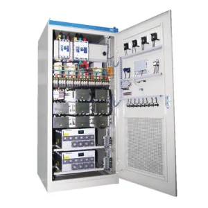
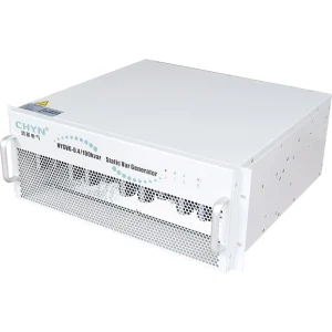
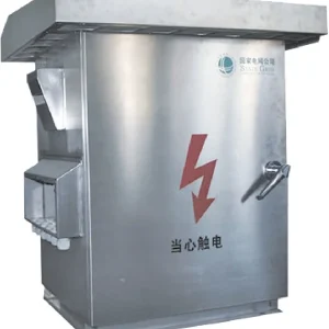
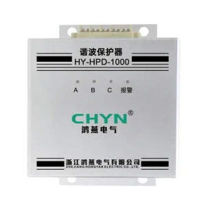
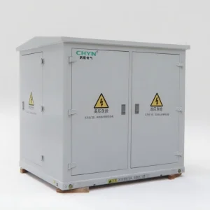
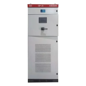
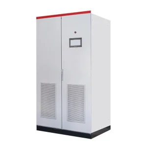
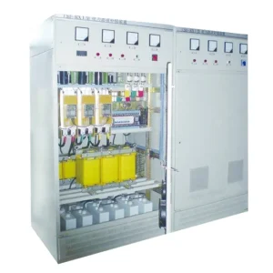
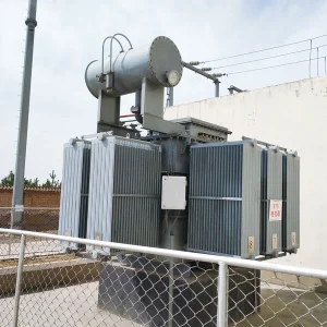
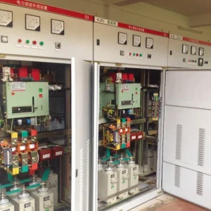
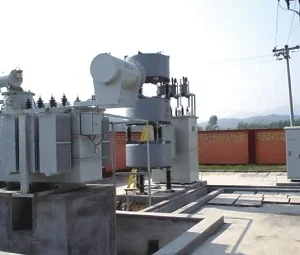
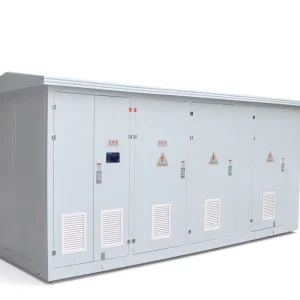
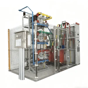
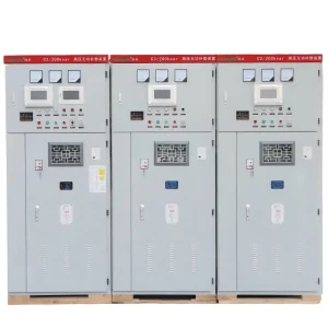
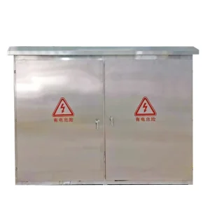
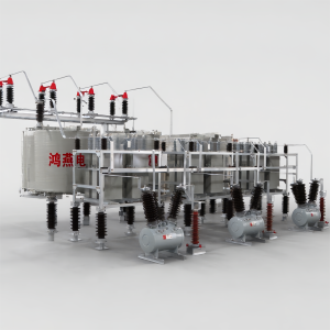
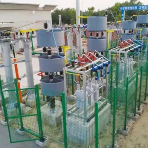
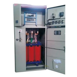
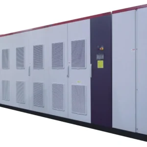
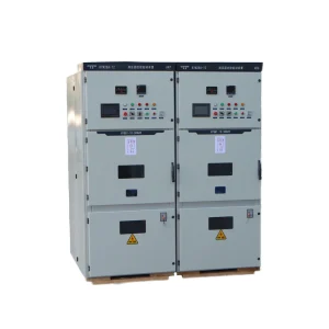
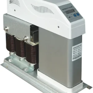
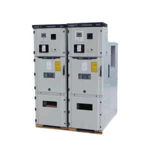
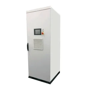
The CHYN HYTBB medium- and high-voltage reactive compensation equipment page describes several arrangements and configurations. Identify the exact unit, connection and protection scheme before applying any diagnosis. A photograph of an outdoor installation does not establish the internal fuse arrangement or the expected capacitance of a particular phase.
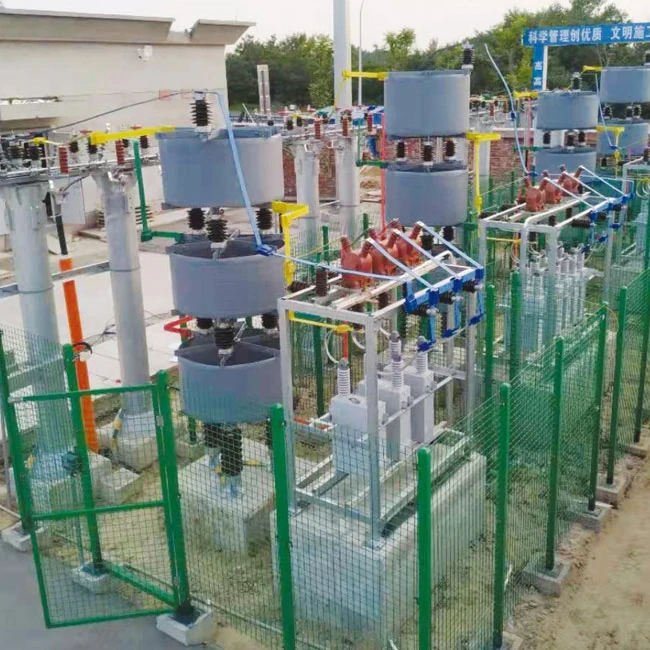
Preserve phase labels, rack positions and capacitor serial numbers. A useful investigation connects each measurement to a physical location. Without that mapping, a low group reading can lead to replacing an unrelated unit or losing the original balance arrangement. Record any previous substitutions, including their rated voltage and capacitance.
Correct the comparison for voltage and frequency
For an ideal capacitor branch at sinusoidal steady state, Q = 2πfCV², using the voltage actually applied across that branch. Here Q is reactive power in var, f is frequency in hertz, C is capacitance in farads and V is RMS volts. A complete bank calculation must follow its star, delta or series-parallel connection. The bank line voltage cannot simply replace an individual capacitor's applied voltage.
For the same healthy bank at unchanged connection and frequency, reactive output scales approximately with the square of voltage. An illustrative 1,000 kvar bank rated at 10 kV would produce approximately 902.5 kvar at 9.5 kV if its capacitance and frequency were unchanged. That 9.75% reduction comes from voltage alone and is not evidence of a 9.75% capacitance loss.
If the same bank instead delivers 850 kvar at 9.5 kV, its apparent capacitance-related output ratio is 850 ÷ 902.5, or approximately 94.2%, provided every intended branch is connected and the readings represent comparable fundamental-frequency conditions. The difference is a reason to investigate, not a diagnosis or a rejection limit. Harmonics, metering definitions and series reactors can invalidate the simple comparison.
Do not use this calculation to infer a unit's condition while ignoring fuse status or the switching sequence. It is a screening tool for deciding whether the output warrants further investigation. The isolated capacitance record and equipment-specific criteria remain necessary for a replacement decision.
Use the symptom to select the next evidence
| Observed pattern | Possible explanation to examine | Record that separates the causes |
|---|---|---|
| All phase currents decline with voltage | Expected voltage-dependent output | Same-time voltage, frequency and connected-step record |
| One step produces little or no change | Unavailable branch or switching-path issue | Step command, status, protection and branch-current evidence |
| One group differs from its baseline | Unit change, fuse operation or connection difference | Mapped unit measurements and original topology |
| Capacitance changes after lead arrangement changes | Test configuration or parallel-path influence | Connection sketch, isolated boundary and repeated readings |
| Output looks normal but a unit shows damage | A condition not resolved by total kvar | Inspection findings and manufacturer-directed assessment |
The table is an investigation framework rather than a failure classification standard. Fluke's capacitor troubleshooting guidance supports using current records, inspections and de-energized capacitance checks together. Its low-voltage measurement examples must not be copied as a medium-voltage work procedure.
Establish a repeatable capacitance baseline
Gather factory reports and commissioning records before testing. Note whether the earlier value represented an individual unit, a series group, an entire phase or a terminal-to-terminal combination. The same numerical unit does not make unlike test boundaries comparable. Record test frequency, instrument identity and relevant environmental conditions with each reading.
A PacifiCorp commissioning specification filed with the Utah regulator illustrates the value of measuring phase capacitance and logging individual cans against their physical locations. It is a utility project document, not a universal acceptance specification for every industrial bank. Use the applicable manufacturer and project requirements for the actual test.
Where earlier records are missing, label new readings as a new baseline rather than inventing a historical trend. Comparing like units may help identify an outlier, but it does not replace their approved tolerances. Explain whether replacements or configuration changes mean that the original factory grouping is no longer present.
Make the isolated test boundary explicit
Capacitors can retain hazardous stored energy after disconnection. The responsible electrical team must follow the bank manufacturer's isolation, discharge, absence-of-voltage verification and grounding procedure before intrusive work. A controller showing zero kvar does not prove that the equipment is safe to touch. Do not infer a safe waiting time from a different product or from a generic internet table.
Define which connections may be removed for the measurement and how the approved safe condition will be maintained. Parallel units, discharge components and connected instruments can affect the reading. Any temporary change belongs on a controlled test sheet with restoration checks, so a diagnostic disconnection does not become an unnoticed defect when the bank returns to service.
Use a suitable capacitance instrument and its approved method. Check repeatability before treating a small difference as deterioration. If a reading changes substantially with the lead arrangement or test boundary, resolve that issue first. Insulation, dielectric-loss and discharge-device tests are separate assessments where required; a plausible capacitance value does not prove that all those functions are healthy.
Interpret changes according to capacitor construction
Capacitance loss is one possible symptom, not a universal signature of every power-capacitor failure. A disconnected parallel element reduces effective capacitance, while bypassing a section in a series path can change the equivalent capacitance in the opposite direction. Therefore, an increase is not automatically reassuring, and a lower phase current does not identify a failed element on its own.
Ask the manufacturer how the actual construction and fuse arrangement translate an internal change into the measured terminal value. Keep the discussion tied to the supplied drawings. Do not transfer a rule for a self-healing low-voltage capacitor to a medium-voltage series group merely because both devices are called power capacitors.
For an unbalance alarm, coordinate these measurements with the bank's unbalance protection scheme. Capacitance investigation asks what has changed electrically. Relay investigation asks whether the protection detects the required condition. Neither result alone proves that the complete bank is ready to return to service.
Choose a compatible repair rather than matching kvar alone
Provide the supplier with the failed or suspect unit's identification, measured values, original group record and operating conditions. Request compatibility confirmation for capacitance, voltage rating, insulation arrangement, discharge provision and protection scheme. The same nominal kvar printed on two units does not establish that they can be exchanged in a series-parallel bank.
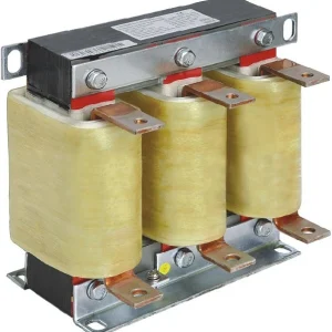
If a reactor is present, assess the branch as a coordinated combination. A change in capacitance changes its electrical relationship with the reactor, so replacing capacitors without reviewing the branch can alter the intended performance. The companion discussion of filter reactor replacement explains why component changes require a system-level check.
Do not enlarge the bank merely to conceal output that has been lost through unavailable branches or damaged components. Correct the identified condition, then compare the restored equipment with the remaining site demand. Expansion is a separate design decision requiring updated fault, switching and harmonic assessments where applicable.
Close the investigation with output and protection evidence
Before energization, account for temporary leads, restored connections, protective settings and the final approved configuration. Record the responsible person's release and any remaining restrictions. After the authorized return to service, compare the connected-step response and phase values under documented operating conditions.
A good closeout package contains the initial symptom, voltage-normalized screening calculation, location-based capacitance results, accepted replacement details and post-repair observations. It also states what was not tested. This allows the next inspection to distinguish a new trend from a change that was already evaluated, while avoiding repeated replacement of healthy capacitors based on total kvar alone.
Further learning: reactive compensation fundamentals
This NPTEL IIT Guwahati lecture explains the basic idea of reactive power compensation. It helps connect capacitance and reactive output; it is not a practical capacitance-testing demonstration or a medium-voltage safety procedure.
Watch the educational lecture on YouTube.
Frequently asked questions
Does a lower kvar reading prove capacitance loss?
No. Verify voltage, frequency, connected steps and measurement definitions first. Confirm a suspected capacitance change using comparable isolated measurements and the supplied equipment criteria.
Can a damaged capacitor show increased capacitance?
Depending on the construction and series-parallel arrangement, some internal changes can increase equivalent capacitance. Interpret the result against the actual topology rather than assuming every failure reduces it.
Is one universal percentage suitable for replacement?
No. Apply the capacitor manufacturer's limits, the bank design and the project's protection requirements. A screening difference is not automatically a replacement threshold.
Can a replacement be selected by kvar alone?
No. Verify electrical and construction compatibility, including capacitance, voltage rating, connection, discharge provision and any coordinated reactor or protection arrangement.