
 Zhejiang Hongyan Electric Co., Ltd.






































After a capacitor element or unit fails, capacitor bank unbalance protection watches the unbalance that appears, so a small unbalance can alarm and a larger one can take the bank offline before remaining units stay in service at a higher voltage. A failed element or unit can leave only a slight change in ordinary phase current, so the useful comparison is unbalance against a healthy bank. The printed unbalanced-load words name that function beside overcurrent, overvoltage, and short-circuit protection.
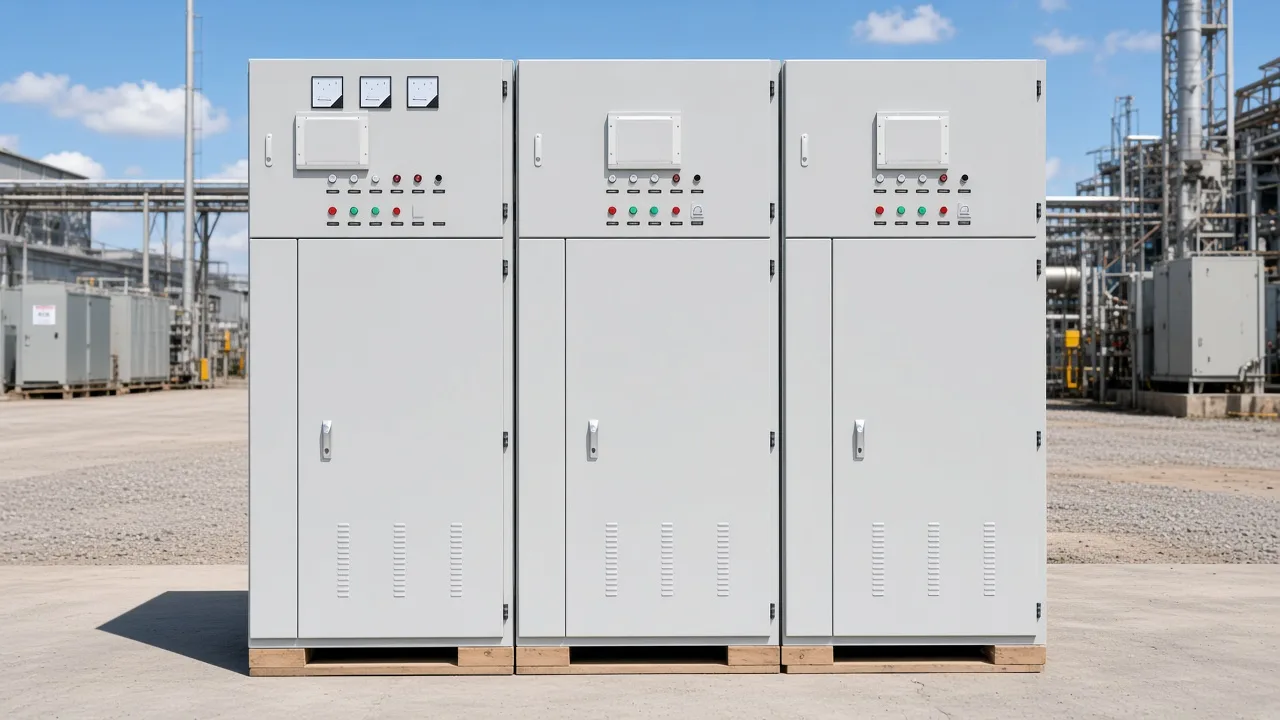
What Unbalance Protection Watches After an Element or Unit Fails
After a capacitor element or unit fails, unbalance protection watches the unbalance inside the bank, alarms when that magnitude is small, and trips the bank when the unbalance is high enough to cascade. Remaining elements can stay in service at a higher voltage, which is why the bank comes offline before that stress continues. The University of Idaho dissertation describes unbalance protection as the primary detection of unit-failure unbalance, with an alarm for a small magnitude and a trip when the unbalance could cascade.
A capacitor element is the internal section inside a capacitor unit, and a capacitor unit is the can that holds those sections. An element fault welds the foils together. After an element fault welds the foils, the remaining capacitor elements in that parallel group stay in service at a higher voltage than before the fault, which is the account in shunt capacitor bank design and protection basics.
Unbalance detection has a stated purpose in that same family of explanations. The scheme removes the bank after a failure and fuse operation so the remaining capacitor units do not see a damaging overvoltage across the group where the failure occurred. That purpose is about the voltage left on the surviving elements, and it stays separate from any pickup printed for a particular cabinet.
A unit failure is the whole can going bad inside the bank, while an element failure can be one internal section welding shut. Either event can leave neighboring sections in service. The watch is the unbalance those events leave behind, with a small magnitude available for an alarm and a cascade-sized magnitude available for a trip.
Cascade, in this use, means one failure raises the voltage on what remains until more elements fail. Removing the bank is the trip outcome when the unbalance reaches that risk. An alarm is the earlier announcement, while the magnitude is still small and the bank can stay online.
Procurement language sometimes asks only whether unbalanced-load protection is named. The watch itself is the unbalance after the element or the unit fails, tied to the higher voltage on what is still in service. A name on a protection list and the behavior after a failure answer two different questions, and this section answers the behavior.
Why the Failure Shows Up as Unbalance Rather Than a Large Phase-Current Change
A failed capacitor element or unit shows up as unbalance because the failure is only a slight change in ordinary phase voltage and ordinary phase current, so the failure is watched as unbalance against a healthy bank. Levels on a phase meter can still look close to the earlier reading. Healthy balance is the bank before that failure, used as the reference for the comparison.
That is why a walkdown that only reads phase amperes can miss the event. Neutral unbalance is the comparison practitioners reach for when the phase reading barely moves. A forum reader expects the neutral unbalance current called I0, on that reader's own bank, to rise when one capacitor fails, and that expectation is that reader's language only.
| What is watched | What the comparison uses | What ordinary phase current supplies |
|---|---|---|
| Unbalance after an element or unit failure | Comparison with a healthy bank | A slight change that can look ordinary |
| Alarm | A small unbalance magnitude | No separate small-magnitude flag on phase amperes |
| Trip | Unbalance high enough to cascade | No cascade judgment from phase amperes alone |
| Remaining elements | Higher voltage on elements that stay in service | The voltage rise on those internal sections |
From the field: A contractor argues that a measuring core is better for small currents on a double-star bank — the Eng-Tips archive is the source of that concern, and the thread's ampere examples stay inside the thread.
Practitioners on that thread are arguing about seeing a small steady-state change at the neutral of a double-star bank. The concern is a field argument about a measuring core. The double-star arrangement in that concern is the bank the contractor was discussing, and it does not assign a current rating to the HYTBB cabinet.
A large phase-current change would be easy to see on an ordinary ammeter. Element and unit failures are described as slight changes, so the protection compares the bank with its healthy balance. Waiting for phase current to become obviously large leaves the unbalance unwatched.
What Alarm and Trip Mean Without a Setting Table
Alarm means the unbalance magnitude is small enough to announce and still leave the bank in service. Trip means the unbalance is high enough to potentially cause a cascading failure, so the bank is taken offline. Neither word, on this cabinet, arrives with a printed percent, a printed delay, or a printed failed-unit count.
Papers and course notes elsewhere attach percentages and delays to those two words. Those figures stay with the documents that printed them. Project design still has to supply any pickup, any delay, and any failed-unit count when a specification asks for them.
The printed unbalanced-load line names the function and does not print an alarm current, a trip threshold, a percent overvoltage, or a failed-unit count. Small and cascade-sized stay qualitative words in this explanation. They follow the split between an alarm and a trip, and they are left as words rather than converted into a relay sheet.
A setting table would need a pickup, a delay, and a count of failed units. None of those three items is part of the printed name. Readers who need the numbers still take them from the project design that specifies the relay.
How the HYTBB Product Line Fits the Printed Unbalanced-Load Words
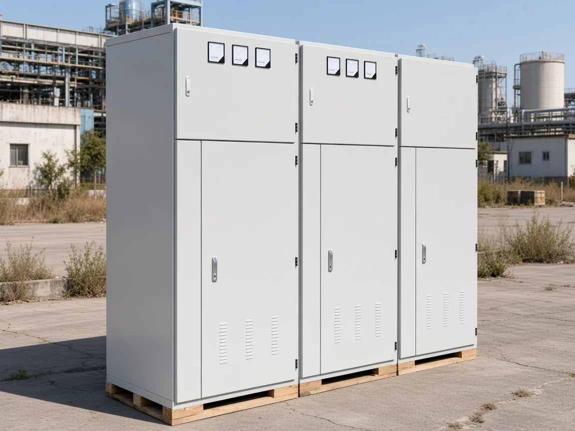
The working-principle description equips the cabinet with comprehensive protection, including overcurrent, overvoltage, unbalanced load, and short-circuit protection. That printed unbalanced-load line names unbalanced load and does not print a sensing device, an alarm current, a trip threshold, or a failed-unit count. A plant buyer can also read capacitor unbalance protection as the same watch, while the cabinet's own name is unbalanced load protection, listed beside overcurrent protection and overvoltage protection.
CHYN is the brand line, and the company named with the cabinet is Zhejiang Hongyan Electric Co., Ltd.
The HYTBB medium- and high-voltage reactive power compensation cabinet is described as a shunt capacitor bank that compensates inductive reactive power on power-frequency systems. The overview states rated voltages from 1 kV to 35 kV.
The parameter table states rated voltage as 10(6)–35 kV. The parameter table states rated frequency as 50 Hz.
The cabinet may operate alone or be combined with KYN28/KYN61 switchgear, and compensation may be fixed or configured for manual or automatic group switching. Series-reactor notes and the power-factor statement are other printed lines. Unbalanced-load protection is the line a plant reader is checking when the question is what the protection list actually names.
The high-voltage power factor compensation series repeats the shunt-bank overview and leaves the unbalanced-load line on the cabinet description. Neighboring compensation types sit in that series. The protection sentence used here is the cabinet description, where the four names appear together.
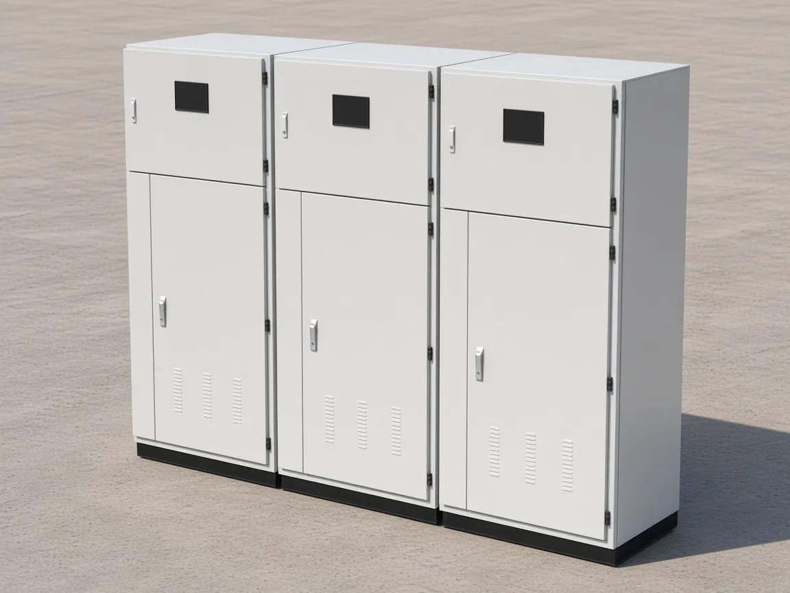
Unbalanced load protection is the name on that list for the watch after an element or unit fails, and it sits beside overcurrent protection and overvoltage protection.
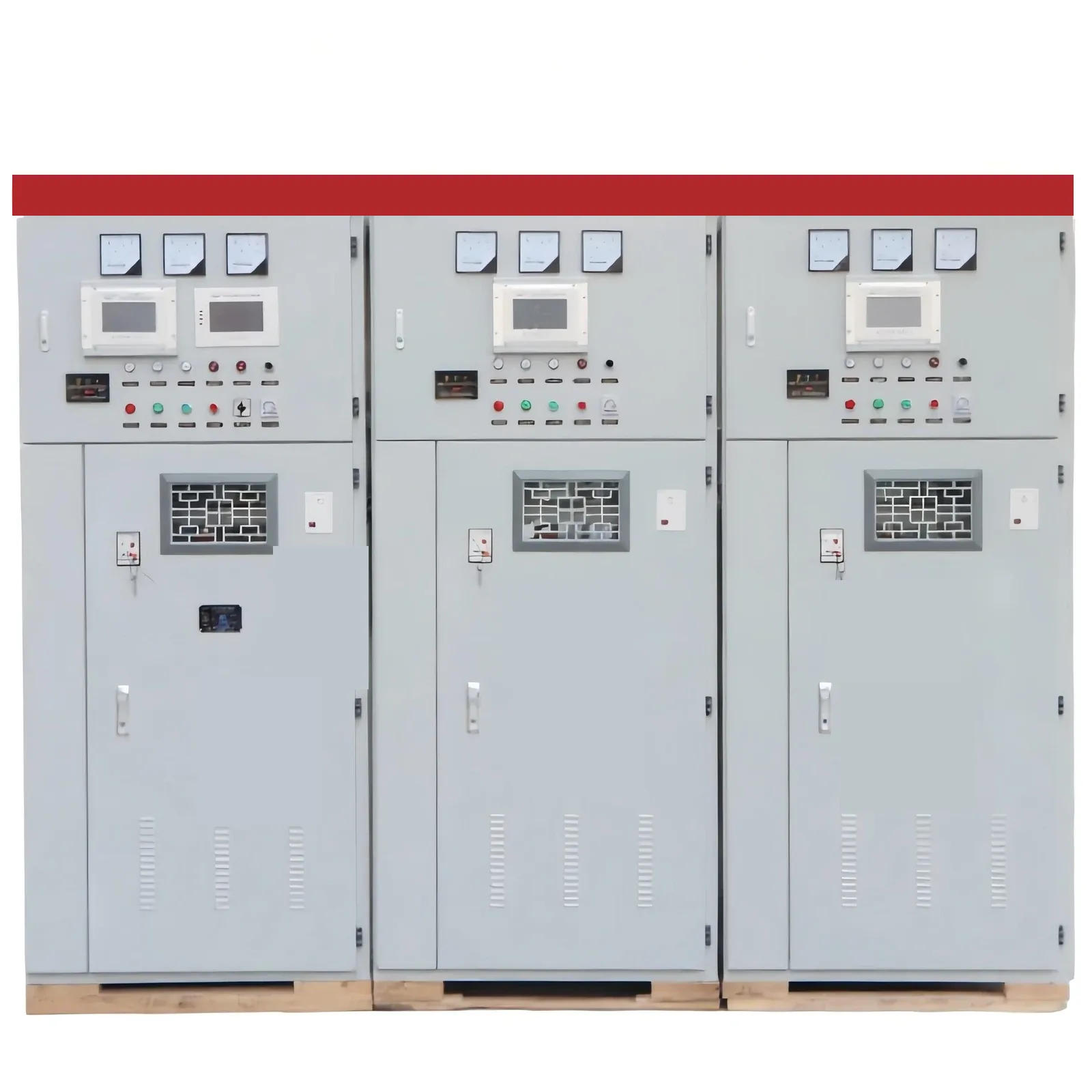
The voltage, frequency, neutral, and residual-voltage rows keep their own printed words beside that named function.
| Printed item | Wording kept | Role beside the unbalance function |
|---|---|---|
| Unbalanced load | Named with overcurrent, overvoltage, and short-circuit protection | Named function on the protection list |
| Overview voltage | 1 kV to 35 kV | Overview range for the shunt cabinet |
| Parameter-table voltage | 10(6)–35 kV | Separate rated-voltage row |
| Rated frequency | 50 Hz | Frequency cell |
| Isolated neutral | Its own neutral-connection phrase | Neutral cell |
| Non-effective grounding | A separate neutral-connection phrase | Neutral cell |
| Three-minute residual voltage | Below 50 V within three minutes after disconnection | Performance-features statement |
| Five-minute residual voltage | Below 50 V within five minutes after disconnection | Working-principle statement |
| 1.0× rated voltage | Long-term operation | Operating line |
| 1.3× rated voltage | Short-duration withstand, length not printed | Withstand line |
How the Two Printed Neutral Phrases Stay Separate From the Unbalance Function
The parameter table prints isolated neutral as its own neutral-connection phrase, and that phrase belongs to the neutral cell rather than to the unbalance function. The same cell prints non-effective grounding as a separate phrase, and that second phrase also belongs to the neutral cell rather than to the unbalance function.
A reader who wants the theory of a star point left off ground already has another article for that job. Capacitor bank unbalance protection remains the watch after an element or unit fails.
Isolated neutral and non-effective grounding remain the phrases in the neutral cell.
How the Two Printed Residual-Voltage Times Stay Separate From Unbalance Protection
Once the cabinet has been disconnected, residual voltage belongs to discharge and not to the unbalance watch. On this shunt cabinet, performance features say the residual voltage drops below 50 V within three minutes after disconnection. Working principle says the residual voltage drops below 50 V within five minutes after disconnection.
The three-minute line is the performance-features statement. The five-minute line is the statement on the discharge resistors of each capacitor group.
Long-term operation is printed at 1.0× rated voltage, and that multiple is an operating line for the cabinet. Short-duration withstand is printed up to 1.3× rated voltage, and that multiple is a withstand line for the cabinet. The short-duration length of the 1.3× withstand is not printed on the cabinet description, so no minute count is added to that withstand line.
Those operating and withstand lines describe voltage the cabinet is said to run at or to withstand. Capacitor bank unbalance protection still watches unbalance after an element or unit fails. A relay pickup remains a project number, while these voltage multiples stay the printed operating line and the printed withstand line.
What Stays With the Fundamentals, Ungrounded-Bank, and Fuseless-Bank Articles
Shunt-bank fundamentals stay with shunt capacitor bank fundamentals and protection. Neutral-connection theory stays with ungrounded capacitor bank. The fuseless-versus-fused unit choice stays with fuseless capacitor bank.
The IEEE PAR page for PC37.99 states that the guide applies to the protection of shunt power capacitor banks and filter capacitor banks. The same PAR states that the guide does not include pole-mounted capacitor banks on distribution circuits or capacitors connected to the terminals of rotating machines. That scope marks which banks the guide names.
Readers who want element-and-unit behavior as a general bank lesson, the meaning of a neutral left off ground, or a unit-construction comparison, already have those three posts. This explanation stays on what unbalance protection watches and on what the printed unbalanced-load line says. Pole-mounted distribution banks and machine-terminal capacitors sit outside the guide scope the PAR states.
FAQ
What does capacitor bank unbalance protection watch after a capacitor element or unit fails?
It watches the unbalance that a capacitor element or unit failure leaves inside the bank. A small magnitude can raise an alarm, and a magnitude high enough to cascade can trip the bank. Remaining elements in the parallel group can stay in service at a higher voltage after the foils weld.
Why can that failure stay small in ordinary phase current?
A failed element or unit is described as only a slight change in ordinary phase voltage and phase current. The comparison that shows it is unbalance against a healthy bank. Phase amperes can still look close to the earlier reading while that unbalance is the quantity being watched.
What does the printed unbalanced-load line say on the HYTBB cabinet?
The cabinet description names comprehensive protection that includes overcurrent, overvoltage, unbalanced load, and short-circuit protection. Unbalanced load is the name in that list, beside the other three functions. The line is the printed name of the function.
Does that printed line include an alarm current or a trip threshold?
The printed line names unbalanced load and leaves out a sensing device, an alarm current, a trip threshold, and a failed-unit count. Any pickup, delay, or failed-unit count has to come from the project design. The printed name and the relay setting are different pieces of information.
Why are isolated neutral and non-effective grounding kept as two phrases?
Isolated neutral is printed as its own neutral-connection phrase in the parameter table. Non-effective grounding is printed as a separate phrase in that same cell. Each phrase belongs to the neutral cell, and the unbalance function is the protection line that watches a failure.
Why are the three-minute and five-minute residual-voltage lines recorded separately?
Performance features carry the three-minute residual-voltage statement after disconnection. Working principle carries the five-minute statement on the discharge resistors of each capacitor group. Unbalance protection still watches a failed element or unit, and these discharge lines do not set that watch.
Does a 1.0× or 1.3× voltage line set the unbalance relay?
The first multiple is the long-term operating line. The second multiple is the short-duration withstand line, and the length of that short duration is not printed. The unbalance relay still needs its own project setting, because these lines describe operating voltage and withstand voltage.