
 Zhejiang Hongyan Electric Co., Ltd.
A capacitor bank reclosing delay keeps a disconnected bank from being switched back onto an energized bus while its residual voltage can still create unacceptable switching duty. Establish the delay from the bank's discharge arrangement, the allowable residual voltage for the switching scheme and the operating cases covered by the protection design. Use verified open status to start the timing, document how remote and automatic close requests are held, and specify what happens after a protection trip or a controller restart. The appropriate setting depends on the offered equipment and the project study. It cannot be inferred from the bank's reactive power rating.
Identify what remains energized after the switch opens
Opening the bank switch interrupts the connection to the supply. The capacitor elements can retain charge after that interruption. A bus voltage indication can confirm the bus is energized or de-energized at its sensing point, while saying little about the voltage on the isolated side of the open bank switch. Mark both sides on the single-line diagram and identify which points, if any, provide a reliable indication of bank residual voltage.
The voltage difference across the contacts at closing depends on the source waveform at that instant and the residual voltage of the disconnected bank. Under an unfavorable combination, the two can have opposite polarity. The current and voltage transient then depend on the rest of the circuit as well, including source impedance, damping, connection and other capacitor steps. The Western Protective Relay Conference review of capacitor-bank protection explains the difference between switching off, retaining charge and the interlock needed to delay another energization.
Use the shunt capacitor bank fundamentals and protection guide for the broader equipment context. The decision here is narrower. It is how to demonstrate that a close request will wait for the applicable discharge condition when the bank has recently been opened.
Start with the equipment discharge data
Ask which elements provide the discharge path and where they are connected. Obtain the offered unit's guaranteed discharge characteristics, the initial voltage and the conditions under which that guarantee applies. A bank may have several sections, and the readings from one point may not represent every section when internal switching devices or fuses change the circuit. Ask the supplier to explain the sensing boundaries on a drawing and clarify which conditions need a separate lockout.
A single ideal capacitor across a resistor follows V(t) = V0e−t/(RC) after the source is disconnected. In that model the elapsed time to reach an absolute voltage fraction f is −RC ln(f). For instance, a hypothetical effective time constant of 20 seconds gives about 46 seconds to reach one tenth of the initial voltage. This arithmetic illustrates why the starting voltage, allowed fraction and effective time constant matter. It is a teaching model with a single intact discharge path, and the example gives neither an equipment setting nor a safe-to-touch criterion.
For actual equipment, obtain documented tolerances, connection details and limits from the supplier. If a potential transformer or other assembly provides a discharge path, use the applicable design data. Do not substitute the ideal resistance model for a discharge characteristic that behaves differently. The discussion of capacitor bank discharge resistors covers the component role in more detail.
Separate the close request from permission to close
A controller may request compensation as soon as the measured reactive demand rises. The request and the permission to energize a particular step should remain distinguishable in the sequence description. Write down the status that starts the wait, how the status is validated and what clears or restarts the timer. Confirm which conditions are required in addition to elapsed time, such as an available supply, a healthy breaker and the absence of a trip lockout.
| Operating case | Evidence to ask for | Question to resolve |
|---|---|---|
| Normal step opened | Open feedback and a time-stamped demand request | Does the controller hold the request until the step is eligible? |
| Rapid loss and recovery of control power | Restart behavior and retention of valid state | How does the controller handle unknown elapsed time? |
| Open command without proof of opening | Switch feedback and alarm trace | Can timing start from a command when actual switch state is unconfirmed? |
| Protective trip | Trip cause, lockout and authorized reset sequence | Does the design require investigation or reset before another close? |
| Another step stays connected | Switching study with the other step energized | Is remaining switching duty acceptable even after the target step discharges? |
Review local, remote and automatic controls against the same sequence. An operator screen may disable its close button while an independent remote path can still submit a request. The project team should show that all permitted request paths respect the protection design and that any restricted maintenance modes are documented in the approved equipment procedures. In a multi-step bank, keep eligibility tied to the actual step rather than to an unrelated timer.
Coordinate the delay with the switching study
The IEEE capacitor bank overview describes the effect of pre-existing charge and system impedance on energization. It also describes controlled switching that aims to reduce the instantaneous voltage difference across the contacts. The study should consider the actual breaker, bank connection, sensing arrangement and tolerance of the offered switching system. A proposal based on controlled switching should explain what happens if the necessary reference voltage, residual-voltage input or switching accuracy is unavailable.
A bank that has discharged can still produce an energization transient. If another bank remains connected to the same bus, the new step can interact with that energized capacitance. That case requires its own assessment of switching duty. Compare with the back-to-back capacitor bank switching guide and carry relevant neighboring step states into the study. A longer delay addresses residual voltage on the open bank but does not change every condition that causes inrush.
Prepare the quotation and test evidence together
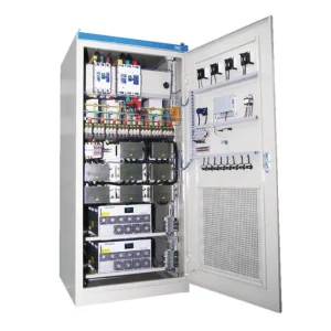
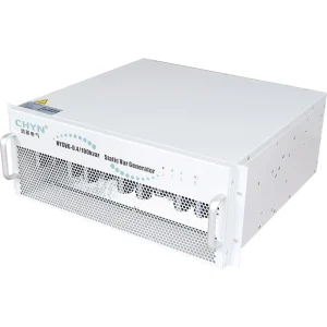
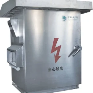
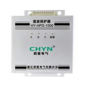
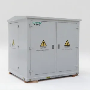
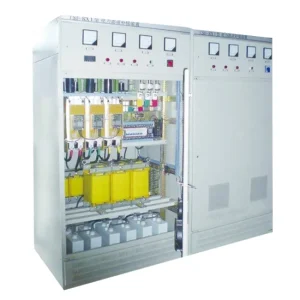
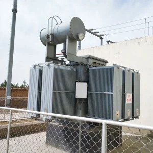
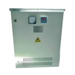
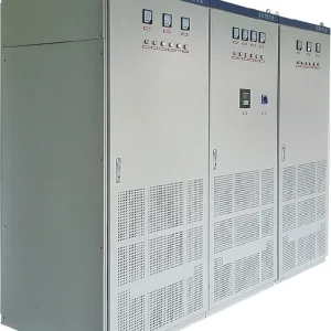
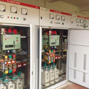
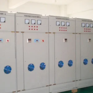
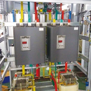
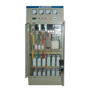
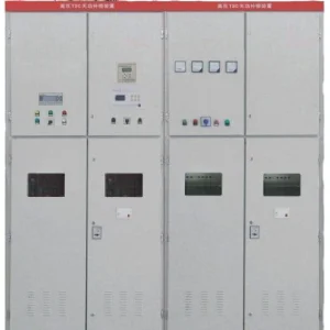
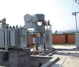
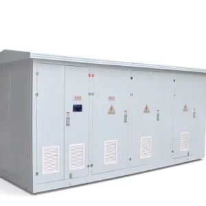
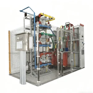
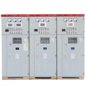
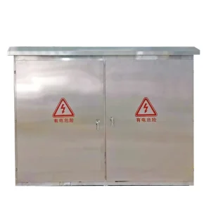
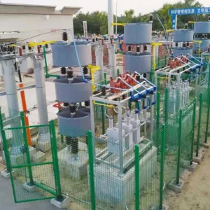
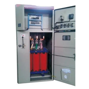
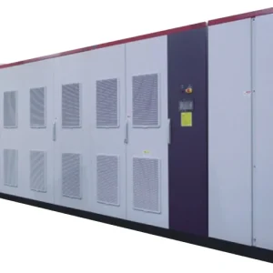
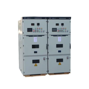
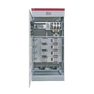
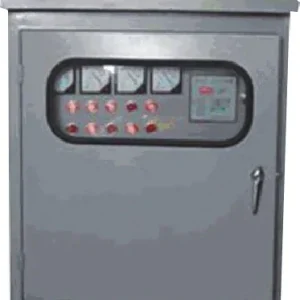
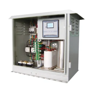
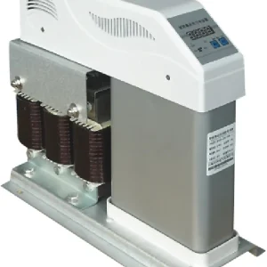
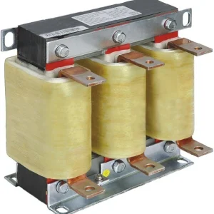
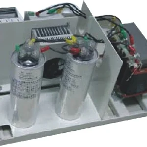
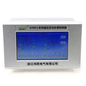
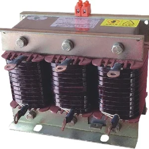
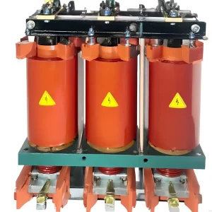
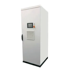
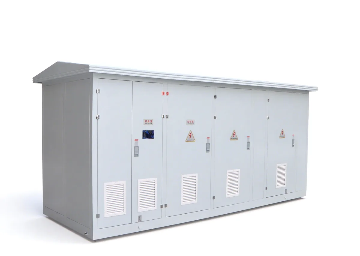
For the CHYN HYTBB outdoor-box reactive power compensation system, submit the source configurations, bank step arrangement, voltage sensing plan and expected demand pattern. Request the offered discharge data, switching duty, control narrative, alarm list and applicable ratings. The photograph identifies the equipment family. The project drawings and supplier documentation establish the configuration actually offered.
Ask the supplier and site team to agree on an approved acceptance method for proving the sequence. A factory test can demonstrate how simulated feedback and commands affect the controller. Site checks can confirm the configured time base, device mapping and responses in the installed system using approved procedures. Set out which checks can be done without energizing the bank and which, if any, require a controlled site test designed by the responsible electrical team.
A usable sequence record includes the open feedback, request time, eligibility transition, close command and switch feedback in a common time reference. Add the fault or power-loss indication when testing abnormal cases. Check that the record identifies the actual step and distinguishes a demand request from a command sent to the switching device. If one test passes only because the request arrived after the delay, repeat the logic check with a request arriving while the step is still blocked.
Finally, keep the delay setting, discharge basis, switch duty and revision of the control sequence with the bank documentation. If a capacitor unit, sensing device or controller is replaced, review whether the original assumptions remain valid. A retained setting is only traceable when the engineering record still explains what it protects and which conditions were verified.
Distinguish a blocked step from a failed compensation command
During operation, a step can be unavailable for a legitimate reason even though the controller continues to see demand. Expose that reason in the event list or operator display. A waiting-for-discharge indication should be distinguishable from a failed-to-close alarm, missing switch feedback and a protective lockout. Otherwise a normal delay can be mistaken for a defective breaker, or a real protection problem can be dismissed as ordinary timer behavior.
Check how the sequence selects another eligible step when the preferred one is still waiting. In some applications substituting a step is appropriate, while in others the step sizes, switching limits or process requirements make waiting preferable. Compare the expected response with the actual compensation requirement during a restart. If the process needs reactive support sooner than the approved bank can provide it, document the gap for the design team to resolve within the switching and protection study.
Further learning
Walter Lewin's physics demonstration explains exponential discharge through a resistor. It illustrates the simplified calculation above using an educational circuit. Actual power capacitor banks require their own discharge data, switching assessment and approved procedures.
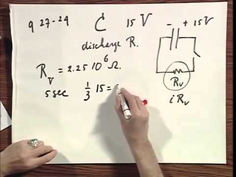
Watch the capacitor discharge demonstration on YouTube.
Frequently asked questions
Does the timer prove the bank is safe to touch?
No. The control timer governs re-energization. Electrical work requires the approved isolation, verification and grounding procedures for the installation.
Is there one delay for every capacitor bank?
No. Select and verify the delay from the offered discharge characteristics, the switching design and the project requirements.
Does a de-energized bus prove the isolated bank is discharged?
No. A bus indication describes its own measurement point. The open bank can retain charge on the other side of the switching device.
Does discharging the bank prevent back-to-back inrush?
No. An energized neighboring step can still affect the switching transient. Include its state in the switching study.