
 Zhejiang Hongyan Electric Co., Ltd.






































After a capacitor bank is disconnected, a discharge resistor for capacitor bank provides a controlled path that bleeds residual voltage down; on a plant HYTBB cabinet that job is stated twice — as a three-minute discharge-circuit result and as a five-minute per-group discharge-resistors result — and those two printed times stay separate.
Industry residual-voltage windows sit beside that job without inventing cabinet ohms, while verify and external shorting stay outside the bleeder’s role. Reclose still cares about trapped charge, and the two HYTBB residual-voltage sentences must be read as separate scopes.
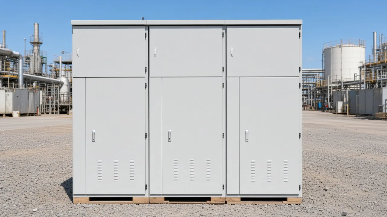
What a Discharge Resistor Does After Disconnection
After isolation, a capacitor bank can still hold a hazardous residual voltage. A discharge resistor (bleed resistor) provides a controlled path that reduces residual voltage after the bank is disconnected.
In plant language, that bleeder is the built-in drain that empties leftover charge once the AC source is gone. Capacitor bank discharge after an open switch is intentional resistor work, not hope that leakage alone will finish the job.
The time constant (RC) of a resistive path sets how fast that decay runs. Rough teaching numbers say voltage falls to about 37% in one time constant, about 5% in three, and near zero after about five.
Many capacitor units use an internal discharge resistor aimed at about 50 V within five minutes. That unit-level line is practice education, not an ohm rating invented for a named cabinet.
A shunt capacitor bank can still present residual voltage at the terminals after the feeder looks dead. The discharge resistor’s job is to bleed that energy down in a controlled way before anyone treats the cans as empty.
The bleed-path scene sits with the resistor job, not with a wait worksheet.
Residual-Voltage Windows Used in Power-Capacitor Practice
Practice windows describe how residual voltage is talked about after disconnect. Common power-capacitor practice targets residual voltage below about 50 V inside class-dependent time windows. Some IEC practice language discusses residual voltage near 75 V within about three minutes.
Independent power-quality writing that restates IEEE Std 18 practice frames internal discharge devices as bringing residual voltage below 50 V in under one minute for capacitors rated 600 V AC and below, and inside five minutes for ratings above 600 V rms. That same summary carries an IEC 60831 residual-voltage aim under 75 V inside three minutes.
These windows describe how industry talk frames the bleeder’s residual-voltage job. They are not a merged wait clock for every plant cabinet, and they are not an HYTBB ohm worksheet.
| Practice language | Typical residual target | Typical timed window | How to use it here |
|---|---|---|---|
| IEEE Std 18 summary (≤600 V AC) | Below about 50 V | Less than 1 minute | Class-dependent practice, not a cabinet listing |
| IEEE Std 18 summary (>600 V rms) | Below about 50 V | Within 5 minutes | Class-dependent practice, not a cabinet listing |
| IEC 60831 summary | Near 75 V | About three minutes | Separate practice language from HYTBB prints |
| Unit internal discharge element | About 50 V | About five minutes | Common unit education line |
| HYTBB discharge circuit | Below 50 V | Within three minutes | Performance Features sentence only |
| HYTBB per-group discharge resistors | Below 50 V | Within five minutes | Working Principle sentence only |
Keep the HYTBB rows as their own printed scopes. Do not average the three-minute discharge-circuit line with the five-minute per-group discharge-resistors line.
Permanent Bleeders Versus Faster Alternate Discharge Paths
Permanently connected bleeders always dissipate some heat while energized; faster discharge paths use switched resistors or reactors with their own thermal limits.
A permanently connected bleeder is ready after every open because the path never leaves the circuit. Switched resistors close a lower-ohm path only after disconnect when the bank must be ready again sooner.
Discharge reactors trade steady heating for a faster drain with their own thermal and duty limits. Method choice answers speed and heat, not whether verify still belongs later.
The focus stays on the resistor’s job after disconnect. It does not walk a full isolate–wait–measure–short checklist, and it does not size ohms for a named cabinet.
Why the Discharge Resistor Is Not a Substitute for Verify or External Shorting
Some work rules keep a multi-minute wait and still require external shorting/grounding — the internal discharge path is not a substitute. Built-in discharge resistors help, but they are not a reason to skip residual-voltage checks.
OSHA’s construction capacitor language tells crews to disconnect the bank and then wait at least five minutes from that disconnect before they apply a short circuit. That wait is a work-step clock, not proof that every bleeder has already finished on every site.
California Title 8 §2940.17 language requires means that reduce residual voltage of a capacitor to 50 volts or less within 5 minutes after disconnection, and it still treats the internal discharge device as no substitute for externally short-circuiting and grounding capacitors.
Multimeter / Test Before Touch stays expected: put a multimeter — or the rated HV instrument your procedure names — on the bank after the wait. Bleeders can fail open, so a timer alone is not a permission slip to touch.
From the field: On a 15 kV arc-furnace capacitor bank lockout debate, practitioners insisted on Test Before Touch even when a grounding switch looked closed, and treated “probably bled down in five minutes” as too thin for retained-charge severity — Mike Holt Forum thread on a medium-voltage cap bank.
A bare screwdriver short is a poor plan for an energetic bank. Forum repair threads still reject screwdriver “zaps” after cracked boards cut bleeder paths; prefer a resistive tool and meter confirmation instead.
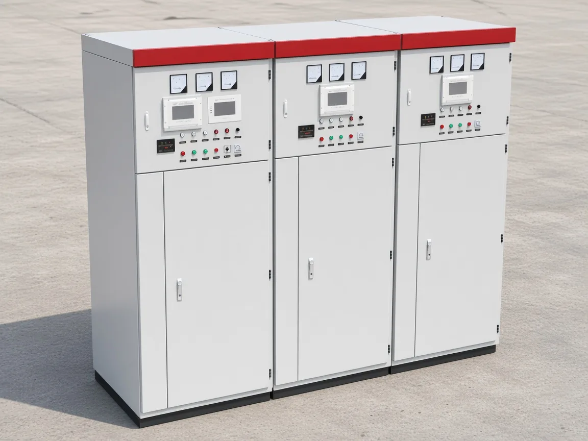
For the full isolate–wait–measure–short sequence, use the sibling on how to discharge a capacitor bank. For the energizing close after a clean discharge, see how to charge a capacitor bank.
Why Trapped Charge Still Matters Before Reclose
Do not treat residual voltage as irrelevant to reclose — trapped charge can drive severe inrush. Reclose / re-energize against a bank that still holds charge, especially with polarity opposing the returning wave, stresses cans, breakers, and nearby buses.
Automatic power-factor steps are commonly held until residual voltage is under about 10% of rated voltage, then allowed to re-energize. That gate is switching practice language, not a maintenance touch limit and not a merged HYTBB wait.
Hold the step until the controller’s residual-voltage or timed interlock agrees. This note flags reclose risk; it does not rewrite a plant switching order or a full discharge LOTO article.
How the Two Printed Residual-Voltage Times Stay Separate
The cabinet prints two residual-voltage results in different sections. On the HYTBB cabinet, the discharge circuit is stated to bring residual voltage below 50 V within three minutes after disconnection. Each capacitor group on that cabinet is stated to use discharge resistors that bring residual voltage below 50 V within five minutes after disconnection.
Those two sentences share a residual-voltage language family, but they name different scopes. One belongs to the discharge circuit. The other belongs to the discharge resistors on each capacitor group.
| Printed scope | Named path | Residual-voltage result |
|---|---|---|
| Performance Features | Discharge circuit | Below 50 V within three minutes after disconnection |
| Working Principle | Discharge resistors on each capacitor group | Below 50 V within five minutes after disconnection |
Do not collapse the two results into one warranty or one average wait. A crew that merges them will follow a sentence the cabinet does not print.
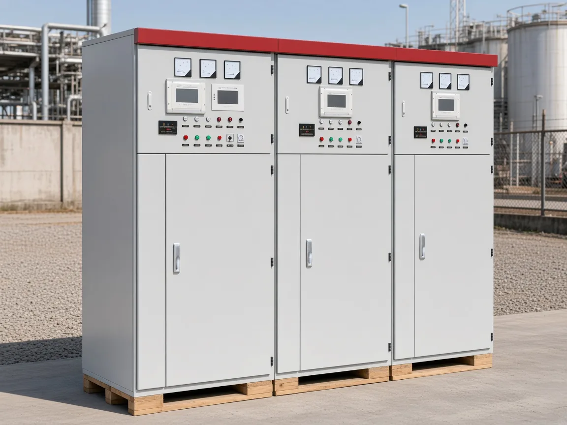
The cabinet scene keeps those printed scopes in view without merging them.
When an HYTBB Cabinet Fits the Discharge-Resistor Job
The product fit is the packaged shunt cabinet that already names the discharge path. Choose the HYTBB Medium and High Voltage Reactive Power Compensation Cabinet when the next step is packaged MV/HV shunt hardware that names discharge resistors and prints both residual-voltage times.
Published ratings include 10(6)–35 kV, 50 Hz, and 50–20,000 kvar, with isolated neutral or non-effective grounding. Keep isolated neutral and non-effective grounding as two phrases in the same neutral cell.
The cabinet description lists discharge resistors among the main components of each group setup. That BOM also names a vacuum circuit breaker, current transformers, a series reactor, high-voltage parallel capacitors, and control or protection units.
| HYTBB ratings scan | Printed value |
|---|---|
| Rated voltage | 10(6)–35 kV |
| Rated frequency | 50 Hz |
| Rated capacity | 50–20,000 kvar |
| Neutral connection | Isolated neutral or non-effective grounding |
| Discharge circuit residual line | Below 50 V within three minutes after disconnection |
| Per-group discharge-resistors residual line | Below 50 V within five minutes after disconnection |
A series reactor on this package limits inrush and helps with harmonic duty. It is not a substitute for reading the two residual-voltage sentences on their own scopes.
This fit is for industrial and utility shunt reactive-power packages, not a home DIY can and not a frequency rating the cabinet does not print. Compare the printed times and the rated frequency with the plant wait and verify procedure, without a standalone enquiry checklist.
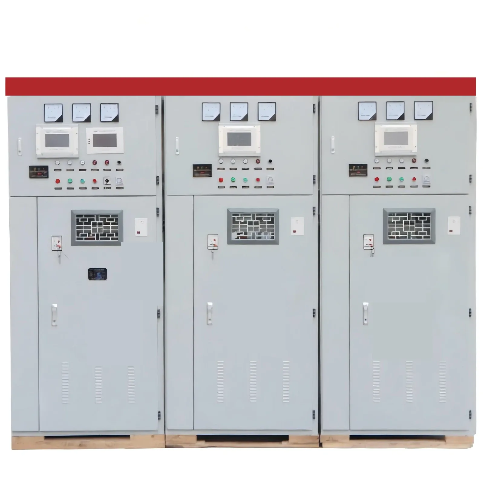
For the product detail set, see the HYTBB medium and high voltage reactive power compensation cabinet. Series context sits under the high-voltage power factor compensation series. Soft boundaries for topology and failed-unit schemes live on the ungrounded capacitor bank and capacitor bank unbalance protection articles.
FAQ
What is the purpose of a discharge resistor on a capacitor bank?
Its job is to give leftover charge a controlled bleed path once the bank is open. In plain language, it is the built-in drain for leftover charge after the switch opens.
Can I discharge a capacitor bank using a resistor?
Yes — that is the bleed-resistor job after disconnect on power capacitor banks. Permanent bleeders are common; switched resistors or reactors are used when a faster path is needed, each with thermal limits of its own.
What size resistor do I need to discharge a capacitor bank?
Follow the equipment’s stated residual-voltage window and any work-rule wait that applies on your site. This article explains the resistor’s job and the two printed HYTBB times; it does not invent an HYTBB ohm or watt rating.
How long does residual voltage take to fall with a discharge resistor?
Industry talk uses class-dependent residual-voltage windows, and some IEC practice language uses its own timed residual target. On the HYTBB cabinet, keep the three-minute discharge-circuit line separate from the five-minute per-group discharge-resistors line.
Do built-in discharge resistors remove the need to measure residual voltage?
No. A bleeder helps, yet crews still confirm residual voltage before they treat the cans as empty. Some work rules keep a multi-minute wait and still require external shorting/grounding — the internal discharge path is not a substitute.
Is a screwdriver short an acceptable discharge method for an energetic bank?
No. A bare screwdriver short is a poor plan for an energetic bank. Prefer a controlled resistive path and then confirm with a meter.
What residual-voltage times does the HYTBB cabinet print?
Read the Performance Features discharge-circuit line for the three-minute residual result, and read the Working Principle per-group discharge-resistors line for the five-minute residual result. Keep those two printed scopes apart.
Why are there two different residual-voltage times on the same cabinet page?
One sentence belongs to the discharge circuit under Performance Features. The other belongs to the discharge resistors on each capacitor group under Working Principle. They are two printed scopes, not one averaged warranty.
References
- Voltage Disturbance page on capacitor bank discharge methods
- OSHA construction rule page for power transmission and distribution capacitors
- California Title 8 page covering capacitor residual-voltage means
- CED Engineering course PDF on shunt capacitor bank design and protection basics
- Mike Holt Forum thread on a medium-voltage cap bank
- EEVblog Forum on the best way to discharge capacitors when repairing