
 Zhejiang Hongyan Electric Co., Ltd.






































How to calculate power factor starts with one ratio: divide real power by apparent power. In plant units that is usually kW ÷ kVA from the same metering interval. The sections below walk single-phase and three-phase paths, run labeled educational examples, flag when cos θ is not enough, and show where a low-voltage static compensation cabinet that switches on measured power factor fits after the number is known.
If you only remember one identity, remember PF = P / S. Everything else—√3 on a balanced feeder, the power triangle, or a true analyzer under harmonics—is a way to get honest P and S before you divide. That is also how to calculate a power factor when someone asks in plain English.

The Power Factor Formula: PF = kW ÷ kVA
Power factor is real power divided by apparent power. Write it as PF = kW ÷ kVA, or PF = P ÷ S when you stay in watts and volt-amperes.
Real power (active power) is the average of instantaneous voltage times current—the watts that heat, move, and light. Apparent power is what the supply must deliver in volt-amperes: for clean single-phase sine waves it is Vrms × Irms.
Reactive power sits on the other leg of the familiar power triangle when those waveforms stay sinusoidal. Then S² = P² + Q², and PF is the cosine of the angle between P and S.
University AC teaching states the same idea as P_avg = VI cos φ, where cos φ is the power factor for sinusoidal voltage and current (HyperPhysics AC power page). Independent formula sheets keep the head identity as PF = P / S and note that cos φ equals that ratio only under sinusoidal assumptions (Atlas of Engineering AC power formula sheet).
Express PF as a decimal (0.80) or a percent (80%). Use the decimal form inside every rearrange: kVA = kW ÷ PF, not kW ÷ 80.
| Path | What you need | Apparent power S | Power factor |
|---|---|---|---|
| Direct | Simultaneous kW and kVA | Metered kVA | PF = kW ÷ kVA |
| Single-phase | Real power + Vrms + Irms | S = V × I | PF = P ÷ (V × I) |
| Balanced three-phase | Real power + V_LL + I_L | S = √3 × V_LL × I_L | PF = P ÷ S |
Keep units consistent. If P is in kW, convert S to kVA (divide VA by 1,000) before you divide.

Single-Phase: Calculate Power Factor from V, I, and Real Power
On single-phase, divide real power by Vrms × Irms from the same interval. That is how to calculate the power factor when you have a wattmeter / analyzer real-power channel plus true-RMS voltage and current.
Steps:
- Measure real power P (W or kW) with a wattmeter or power analyzer—not by multiplying RMS volts and amps alone.
- Measure RMS voltage V and RMS current I at the same electrical point and interval.
- Form apparent power S = V × I (VA), or kVA = V × I ÷ 1,000.
- Compute PF = P ÷ S.
If P is already in kW, PF = (kW × 1,000) ÷ (V × I). The 1,000 converts kilowatts back to watts so the units match volt-amperes.
A clamp that only reports amps cannot invent power factor by itself. You still need a compatible real-power measurement.
When voltage and current are out of phase, V × I overstates the watts that do work. That product is apparent power, which is exactly why the ratio can fall below 1.0.
Three-Phase: How to Calculate PF with √3
For balanced three-phase, apparent power uses the three-phase √3 identity with line-to-line volts and line current. Then power factor is still total real power divided by that total apparent power.
Under balanced sinusoidal assumptions:
S (VA) = √3 × V_LL × I_L
S (kVA) = √3 × V_LL × I_L ÷ 1,000
PF = P_total (kW) ÷ S (kVA)
√3 is about 1.732. Omitting it under those assumptions understates kVA and overstates PF.
Adding √3 does not make a one-CT method valid on an unbalanced or heavily distorted feeder. Use a multi-channel analyzer and its total P and compatible total S when the board is not balanced.
How to calculate the power factor on a three-phase main is therefore not a different definition. It is the same PF = P / S identity with a three-phase expression for S when the balanced shortcut applies.
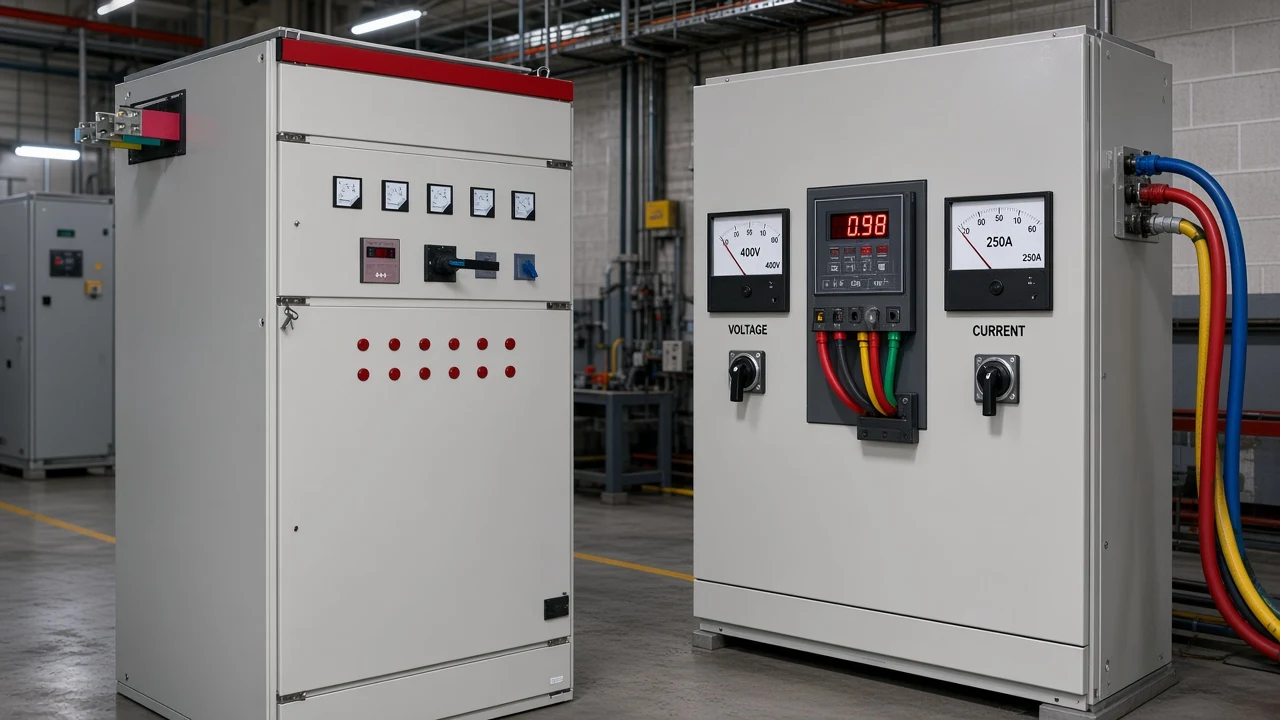
When the sinusoidal power triangle holds, reactive power is the other leg: kVAR = √(kVA² − kW²). That identity helps sanity-check a meter pair. It is not a license to skip real-power measurement and invent watts from amps alone.
Worked Examples: How Do You Calculate Power Factor
How do you calculate power factor on paper once the inputs are locked? Run the arithmetic on stated educational inputs—these are worked examples, not logged readings from a named plant.
| Example | Stated inputs | Calculation | Result |
|---|---|---|---|
| A — direct ratio | 100 kW and 125 kVA | 100 ÷ 125 | PF = 0.80 (80%) |
| B — device scale | 500 W and 600 VA | 500 ÷ 600 | PF ≈ 0.833 |
| C — AIO-style ratio | 800 kW and 1,000 kVA | 800 ÷ 1,000 | PF = 0.80 |
| D — three-phase shortcut | 100 kW, 480 V_LL, 150 A line | S = √3 × 480 × 150 ÷ 1,000 ≈ 124.7 kVA; 100 ÷ 124.7 | PF ≈ 0.80 |
Example A is the classic plant-engineer ratio: if working power is 100 kW and apparent power is 125 kVA, PF = 0.80. Example D uses the balanced three-phase shortcut with simultaneous line quantities.
If your phases are unequal, stop and use analyzer totals instead of one line current.
Rearrangement check: at PF = 0.80, a 100 kW load needs 100 ÷ 0.80 = 125 kVA of supply capacity. That is why feeders and transformers are discussed in kVA even when the process team talks in kW.
Required capacitor kvar to move from one PF to another is a separate calculation. Qc / kvar bank sizing uses Qc = P × (tan φ1 − tan φ2). When you need that path, open the sibling guide on how to calculate kvar for capacitor bank after this page has locked the existing PF.
When cos θ Is Not Enough: True PF vs Displacement PF
When voltage and current are sinusoidal, PF equals the cosine of their phase angle θ. That is why older meters and textbooks call power factor cos θ or cos φ.
It is only the case when both voltage and current are sinusoidal. A true power factor meter computes the ratio of real to apparent power.
Under distortion / true PF conditions from VFDs, rectifiers, and other nonlinear loads, displacement power factor and true PF can diverge. Capacitor banks mainly correct the displacement portion; they do not automatically erase harmonic-driven apparent power.
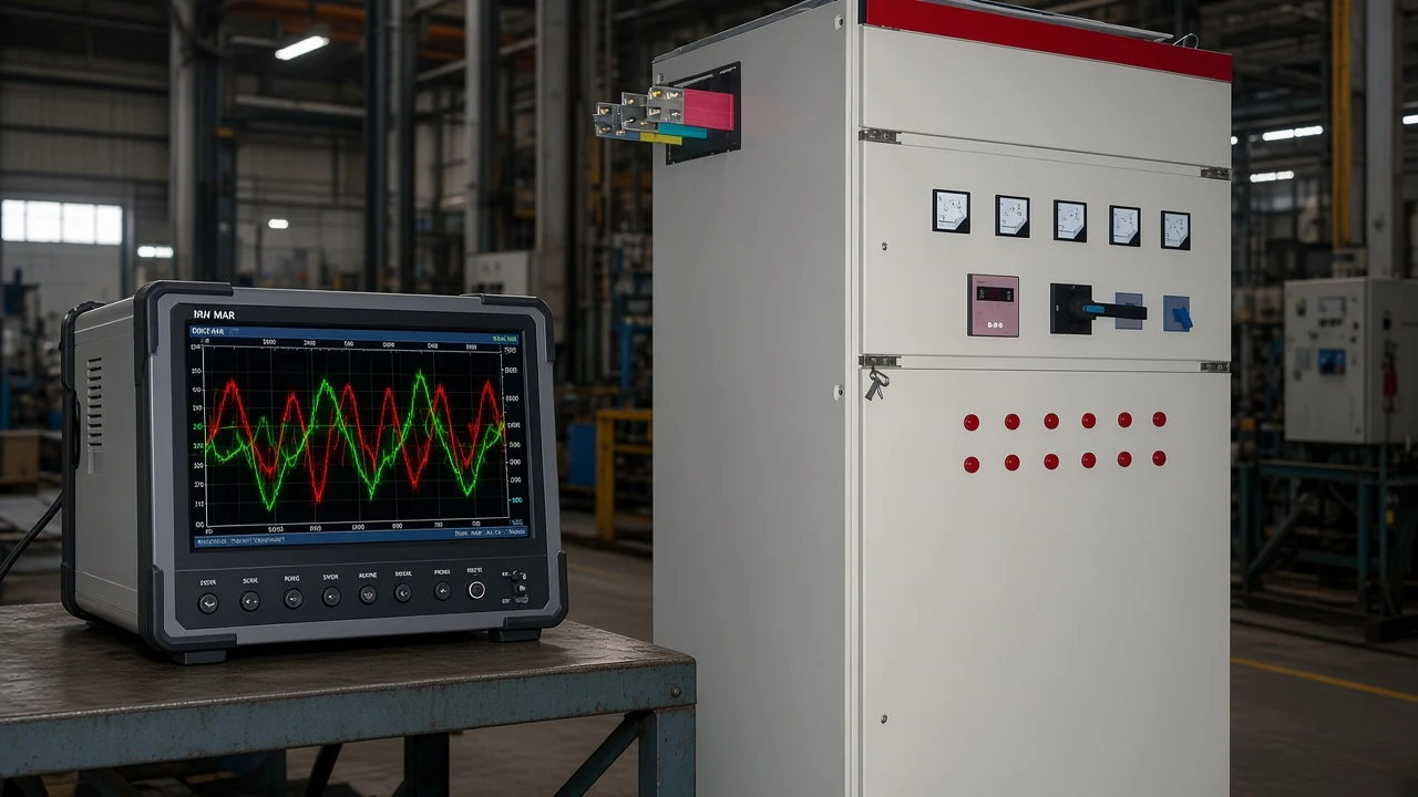
Encyclopedia definitions of power factor keep the same split between the simple phase-shift picture and the more general real-over-apparent definition (Wikipedia power factor article). For plant work, prefer an analyzer that reports true PF over a cos θ-only clip-on when the current waveform is visibly non-sinusoidal.
Field Mistakes That Skew a Power Factor Calculation
Vrms × Irms is apparent power, not automatically real power. Multiplying a true-RMS clamp reading by bus voltage and calling the product “kW” is the mistake that invents a cheerful PF of 1.0 on an inductive board.
From the field: In an EEVblog beginners thread, a reader’s volt-amp product disagreed with a wattmeter until replies pointed out that apparent power is Vrms × Irms, real power needs a wattmeter-style average of v·i, and PF is their ratio—EEVblog thread on electronics math and power factor.
Other common skews:
- Mixing intervals: kW from last week’s demand register with amps from this morning’s walkthrough.
- Using percent in the rearrange: writing kVA = 100 ÷ 85 instead of 100 ÷ 0.85.
- Dropping √3 on a balanced three-phase feeder, or keeping √3 on a clearly unbalanced one.
- Treating a single-phase PF reading on one leg as the whole plant’s PF.
- Confusing kWh energy with kW power when someone asks how do i calculate power factor from a bill alone—energy without demand and PF context is not enough.
Electrician forums hammer the same relationship in plain language: kW = kVA × PF, and at unity PF the two are equal. Motors and other inductive loads push kVA above kW (Mike Holt Forum thread on kW vs kVA).
Which HYTBBJ Fit After You Calculate Power Factor
Once you can calculate the power factor at the correction point, the hardware question is whether a stepped capacitor system should hold that PF near the target your tariff or process needs. For distribution systems with relatively steady inductive loads, a low-voltage static reactive power compensation system that switches capacitor groups from measured reactive demand or power factor is the natural next product fit.
The HYTBBJ Series Low-Voltage Static Reactive Power Compensation System automatically switches capacitor groups according to measured reactive demand or power factor. Capacitor group switching follows measured PF or reactive demand for manufacturing, buildings, and public facilities with relatively steady inductive loads.
It monitors three-phase voltage, current, power factor, and compensation status. The published model code table includes a 0.4 kV system voltage level among the code fields.
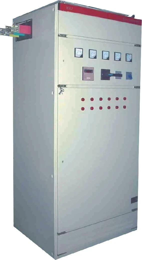
Browse the Low Voltage Power Factor Compensation Series when you need static, dynamic, outdoor, or end-point options. Highly swinging loads may belong on a dynamic series instead of a static step bank.
This page does not invent UL/NEC listings, SKUs, kWh savings, or payback periods. Bring your measured PF, load steadiness, and voltage level to the enquiry.
Sizing the kvar steps themselves is the sibling calculation after PF is known. Do not paste a Qc multiplier table here; open the kvar guide when you are ready to size banks.
FAQ
How do you calculate power factor?
Divide real power by apparent power: PF = kW ÷ kVA (or P ÷ S). Use values from the same metering interval and the same electrical boundary.
How do I calculate power factor from kW and kVA?
Take the kilowatt reading and divide by the kilovolt-ampere reading. Example (educational): 100 kW and 125 kVA give PF = 0.80.
How to calculate PF in a 3-phase system?
Form total apparent power with the balanced shortcut S = √3 × V_LL × I_L when those assumptions hold, measure total real power, then PF = P ÷ S. On unbalanced or distorted systems, use a multi-channel analyzer’s total P and compatible total S.
Is power factor the same as cos φ?
For sinusoidal voltage and current, yes—PF equals cos φ. Under distorted waveforms, compute true PF as P ÷ S; a cos φ-only reading can miss the distortion component.
What does a PF of 0.8 or 80% mean?
It means real power is 80% of apparent power. Only four-fifths of the supplied VA is doing useful work; the rest is reactive (and, under distortion, non-fundamental) burden on the supply.
Can I use V×I as watts in the power factor formula?
No. Vrms × Irms is apparent power in VA.
Real power needs a wattmeter or analyzer average of instantaneous v·i. PF is their ratio.
What is 0.95 power factor?
It is a decimal PF of 0.95 (95%). Many sites treat values near that band as a practical target, but your contract or process may set a different number—this article does not invent a universal tariff rule.
After I calculate PF, how do I size capacitor kvar?
That is a separate calculation: Qc = P × (tan φ1 − tan φ2) for displacement correction. Use the guide on how to calculate kvar for capacitor bank after the existing PF is locked.