
 Zhejiang Hongyan Electric Co., Ltd.





































Knowing how to calculate kvar for capacitor bank reactive demand starts with a short formula: multiply the active power at the correction point (kW) by the difference of the tangents of the existing and target power-factor angles—Qc = P × (tan φ1 − tan φ2). The sections below lock the inputs you need, walk the classic formula and an equivalent multiplier table, work one numeric example, flag the mistakes that produce leading or wrong kVAR, and show when a stepped-bank controller such as HYRPC-130E belongs after Qc is known.
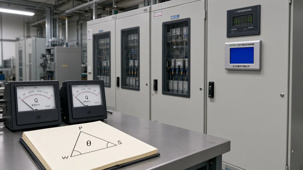
Inputs You Need Before Calculating Capacitor Bank kVAR
Lock correction-point active power P (kW), existing power factor (cos φ), and target power factor before you touch the tangent formula. Capacitor bank kVAR (Qc) is the output of that calculation.
The math is short. The failures almost always start earlier: people substitute transformer kVA for load kW, pull a motor nameplate power factor instead of a measured bus value, or size only for peak production and ignore nights and weekends. Measure or estimate at the same electrical point where the bank will sit—main LV board, MCC, or feeder—because Qc corrects what the meter and the upstream conductors actually see.
| Input | What to use | Why it matters |
|---|---|---|
| Active power P (kW) | Logged or coincident real power at the correction point | Qc scales linearly with P; transformer nameplate kVA alone oversizes |
| Existing PF (cos φ1) | Metered displacement PF or energy-derived average over a work cycle | Wrong φ1 flips the whole result |
| Target PF (cos φ2) | Tariff / contract target, often near 0.95 lagging | Unity targets leave no margin and invite leading PF |
| Load swing | Peak vs minimum reactive demand | Decides if one fixed Qc will overcorrect at light load |
| Voltage (and system frequency if converting to µF) | Actual applied bus voltage; stated system frequency for capacitance checks | Delivered kVAR follows V²; µF conversion needs f |
If you only have active and reactive energy over a shift, you can still form an average cos φ from ΔkWh and ΔkVARh before you enter the formula. That average is educationally the same idea plant engineers use when a dedicated power-factor meter is not available at every board.
Choosing a nameplate unit string or outdoor rack form is a different job—that rating-selection path belongs to a sibling guide and is not expanded here. Configuration choices after you know Qc live in the live capacitor bank design checklist.
The Classic Qc Formula: P × (tan φ1 − tan φ2)
Required capacitor-bank kVAR equals active power times the difference of the tangents of the existing and target power-factor angles. That power factor correction kvar formula is the spine of capacitor bank kvar calculation for displacement correction.
Write:
Qc (kVAR) = P (kW) × (tan φ1 − tan φ2)
where φ1 = cos⁻¹(PF1) and φ2 = cos⁻¹(PF2). Independent electrical education pages state the same relation for power-factor improvement (TutorialsPoint — capacitor bank size calculation; Electrical Technology — kVAR & µF calculator).
On the power triangle, real power P stays the same while the bank supplies capacitive reactive power that shortens the reactive leg. Apparent power S = √(P² + Q²) falls, so line current for the same kW drops. That is why the required kvar for power factor improvement both supports a better metered power factor and frees feeder and transformer ampacity.
Use displacement power factor for this classic arithmetic. Distortion power factor and harmonic-rich buses still need a separate study; the tangent method answers the displacement correction question first.
If you later convert Qc into microfarads for a single-phase check, education sources use C(µF) = kVAR × 10⁹ / (2π f V²) with the applied RMS voltage and the stated system frequency for that site (Electrical Technology). Most industrial buyers stop at kVAR and order standard steps; µF is a verification tool, not the primary purchase unit.
PF Multiplier Table Shortcut for Required kVAR
You can replace the tangent steps with a correction factor / multiplier table so that Qc = P × K for a chosen initial and final cos φ.
Educational correction-factor tables publish K for common starting power factors and targets such as 0.95, 0.97, or unity (ElecDatum — capacitor bank sizing). The table below is a compact educational subset for a 0.95 target—verify any field design against a full table or direct trig for your exact pair.
| Initial cos φ1 | Multiplier K to reach cos φ2 ≈ 0.95 | Meaning |
|---|---|---|
| 0.60 | ≈ 1.01 | Roughly one kVAR per kW |
| 0.70 | ≈ 0.62 | About 0.62 kVAR per kW |
| 0.75 | ≈ 0.46 | About 0.46 kVAR per kW |
| 0.80 | ≈ 0.31 | About 0.31 kVAR per kW |
| 0.85 | ≈ 0.17 | About 0.17 kVAR per kW |
These multipliers are educational illustrations, not CHYN project measurements. They save time on a walkthrough when a calculator is unavailable, and they should land within rounding of the tanφ method for the same PF pair.
Authority topic pages on shunt power capacitors treat automatic switching as a load-tracking control problem: stages come online when demand is high and drop off when demand falls, so a single peak-derived Qc is not left permanently connected on a swinging plant (IEEE TechNav — shunt capacitor switching behavior). That is why a K×P result is the start of a stepped plan, not a forever-on fixed block. Fixed vs switched bank selection follows the Qc number: fixed blocks suit steady loads; switched steps suit swinging plants.
Worked Example: Improving Plant PF from 0.75 to 0.95
For a mid-size plant load, the classic formula returns a concrete kVAR total you can round to standard steps before you choose fixed or switched hardware.
This walkthrough uses educational numbers only.
For a 500 kW load improving from 0.75 to 0.95 lagging, the educational illustration needs about 277 kVAR.
Independent worked examples use P = 500 kW, PF1 = 0.75 (φ1 ≈ 41.4°, tan φ1 ≈ 0.882), and PF2 = 0.95 (φ2 ≈ 18.2°, tan φ2 ≈ 0.329).
Then Qc = 500 × (0.882 − 0.329) = 500 × 0.553 ≈ 276.5 kVAR, commonly rounded to about 277 kVAR and then to a standard step such as 300 kVAR.
Treat these figures as education-only. They match the arithmetic pattern published in independent technical explainers for the same PF pair; they are not a CHYN site measurement.
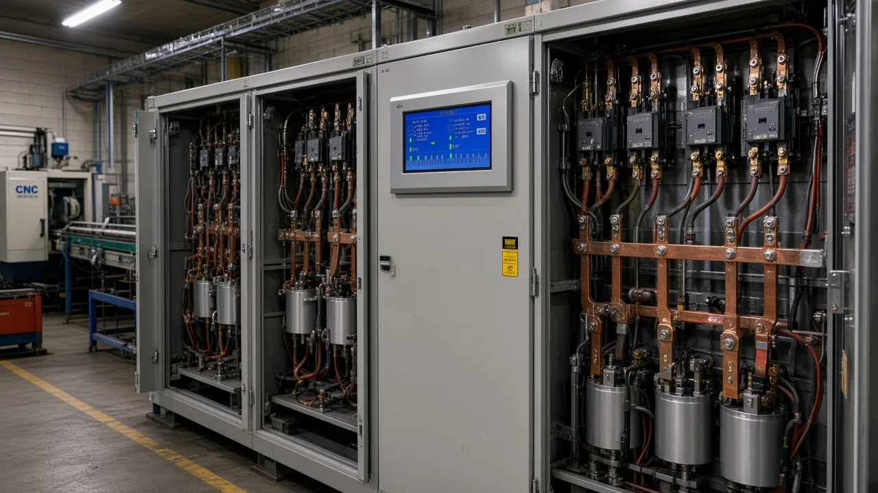
Before you trust any worksheet, confirm the inputs behind the arithmetic—coincident kW, existing and target PF, and whether load swing needs steps instead of one fixed block.
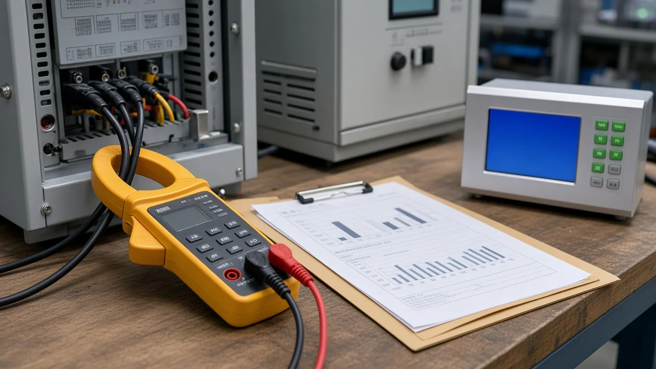
Cross-check with the multiplier view: for cos φ1 = 0.75 toward 0.95, K ≈ 0.46 → 500 × 0.46 ≈ 230 kVAR on some abbreviated tables, while direct trig gives ~277 kVAR. Prefer the direct tanφ calculation for the exact pair, then round to available step sizes and re-check the resulting PF. A second educational path (500 kW from 0.70 to 0.95) lands near 345.5 kVAR on ElecDatum’s worked example—same method, different starting PF.
After you have Qc, decide whether that total is one fixed block or several switched steps. How the bank is arranged, fused, and enclosed is design work covered on the capacitor bank design page; this article stops at the reactive-power number and the control implication.
For readers who still need the mechanism of leading kvar itself, see how do capacitor banks work.
Common Mistakes When Calculating Capacitor Bank kVAR
Most bad bank results come from bad inputs or from treating a peak-only Qc as a forever-on fixed rating.
Using transformer kVA or connected horsepower instead of correction-point kW. Installed capacity is not coincident real power. Qc tracks P; inflate P and you inflate the bank.
Chasing unity power factor. Soft industry guidance targets roughly 0.95 lagging more often than 1.00, because unity leaves no measurement margin and can push light-load periods into a leading condition that some tariffs still penalize (ElecDatum common mistakes; Electricity Forum — PF correction and kVAR sizing).
Sizing a fixed bank on peak load only. When production drops, the same capacitance can drive leading or “negative” kVAR readings. Field discussions warn that legacy capacitance left online after loads change (for example after UPS upgrades) can look like a capacitive plant—and adding still more capacitors is the wrong next move.
From the field: Operators have asked what happens when motors idle overnight while a static bank stays fully online—the power factor can swing leading, and excess capacitance can stir voltage complaints on the next switching event (Physics Forums — leading power factor at night). If meters show negative kVAR after a load change, check whether older capacitors are still online before you increase bank size.
Ignoring voltage-squared output when you interpret a nameplate kVAR. Reactive output of a capacitor scales with the square of applied voltage. A bank labeled for one voltage does not deliver the same kVAR at a much lower bus voltage; community Q&A walks the V² ratio explicitly for that reason.
Skipping harmonic resonance (soft) checks on drive-heavy buses. Displacement Qc can still be correct while a plain capacitor string resonates with nonlinear loads. Industry explainers treat detuning and harmonic checks as a follow-on gate after the tangent math (Electricity Forum). Soft editorial scope only—no invented listing or trip statistics here.
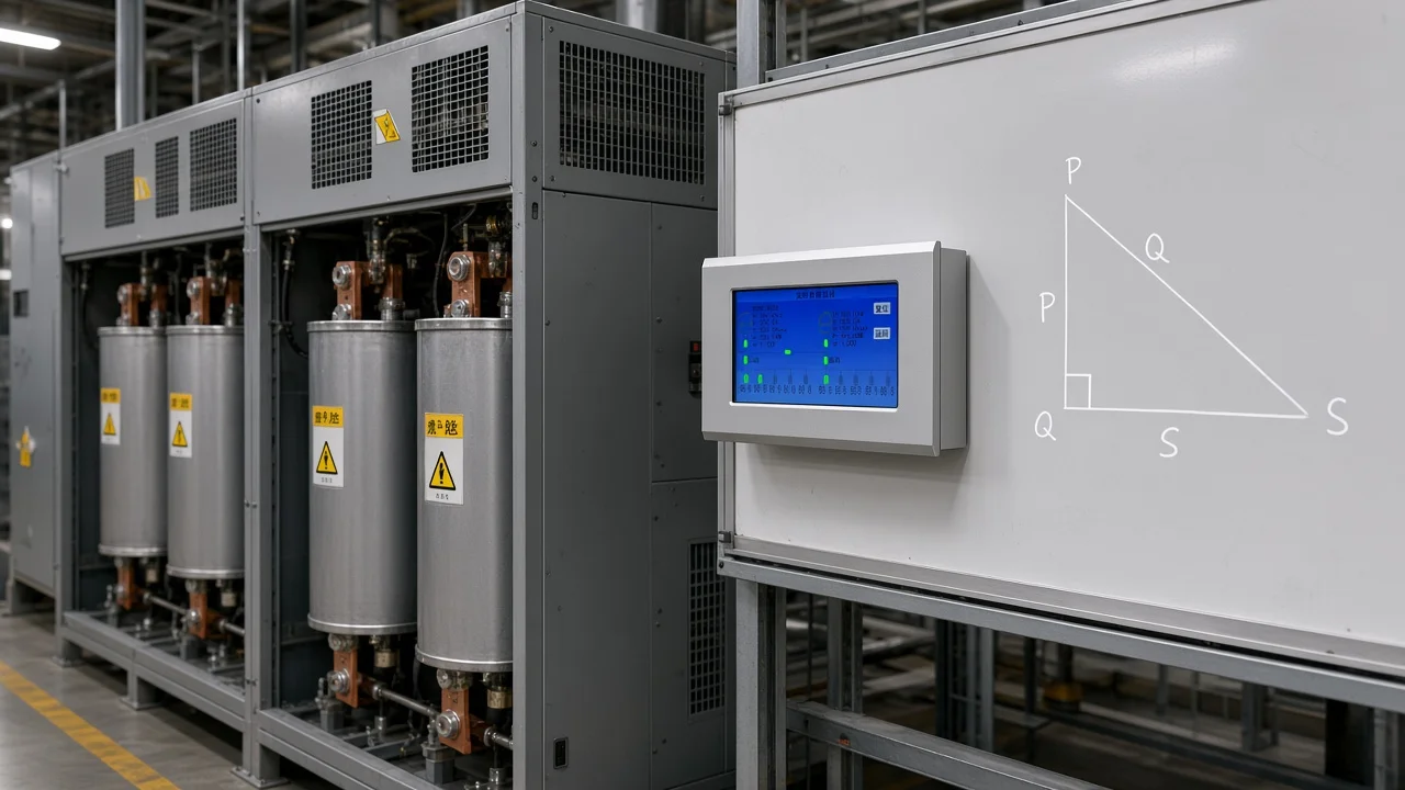
Which HYRPC-130E Fit After You Calculate Qc
Once the required kVAR and step plan are known, a reactive power compensation controller keeps the bank matched to the live load so the calculated target does not become a fixed overcorrection.
The HYRPC-130E Series Reactive Power Compensation Controller is an automatic PF controller built for one to three capacitor banks on low-voltage distribution—typical single-transformer substations and single-source feeders.
It evaluates voltage deviation and reactive power demand, then switches banks automatically with modes such as equal-step, unequal-step, filtering, photovoltaic, and feeder/terminal compensation. Anti-oscillation logic uses a power-factor zone plus ON and reverse OFF delays so contactors do not hunt.
The unit integrates monitoring, event history, interlocking on faults, and RS-485 Modbus-RTU communication. Sampling accuracy for PF, voltage, and current is stated on the product page as error below 0.5%.
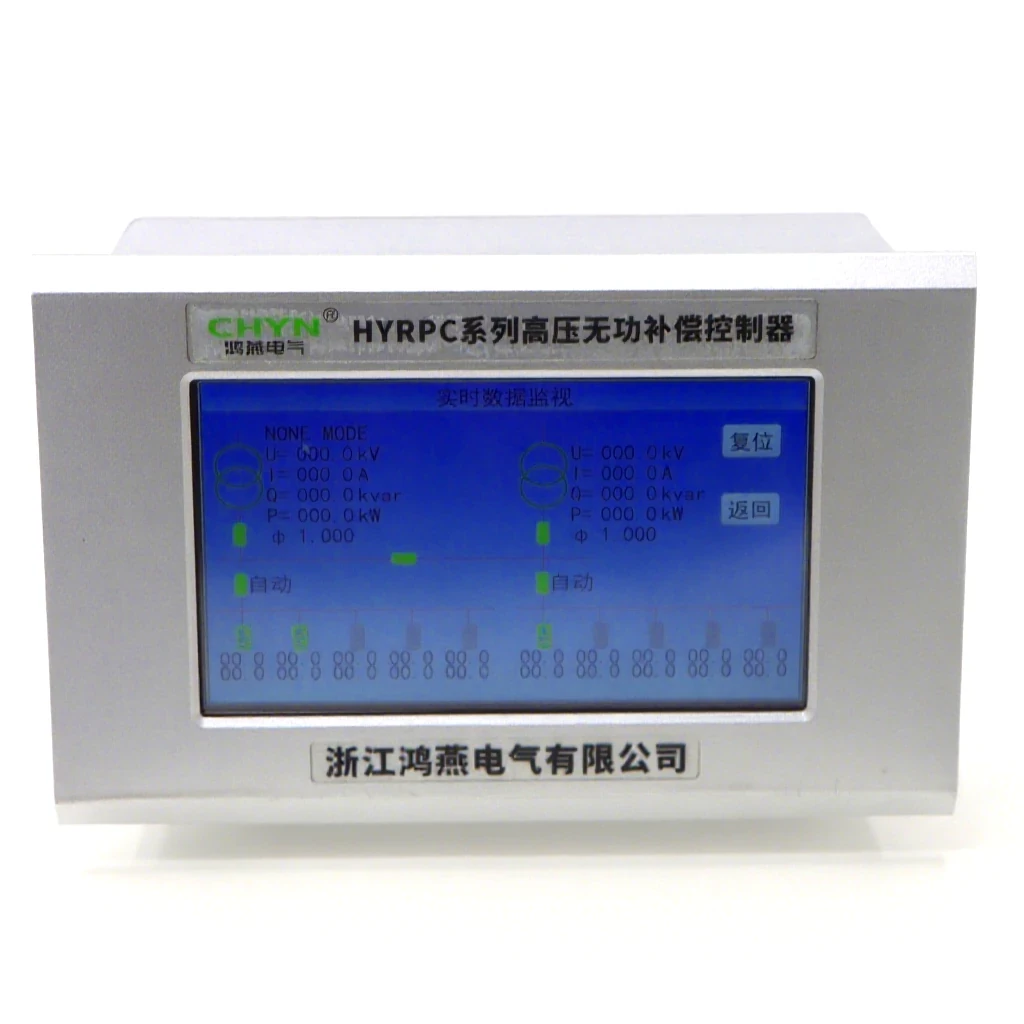
That is the natural hand-off from this calculation article: Qc answers “how many vars,” and HYRPC-130E answers “how those vars stay on target as the plant moves.” It is not the right next click when you still need outdoor MV enclosure design (use the design guide) or when the open question is only how to read a capacitor unit’s nameplate rating string.
Browse the broader high-voltage power factor compensation series when the calculated kvar sits on an MV bus package rather than an LV stepped cabinet.
FAQ
What formula calculates capacitor bank kVAR from load and PF?
Use Qc = P × (tan φ1 − tan φ2), with φ1 = cos⁻¹(existing PF) and φ2 = cos⁻¹(target PF), and P in kW at the correction point.
Which measurements do I need before calculating Qc?
You need correction-point active power, existing power factor, target power factor, and a sense of load swing; add bus voltage and the stated system frequency if you convert kVAR to µF.
How do I convert kVAR to microfarads?
Educational converters use C(µF) = kVAR × 10⁹ / (2π f V²) with RMS voltage across the capacitor and the system frequency; three-phase banks need the correct phase voltage for the connection.
How many amps does 1 kVAR draw roughly?
For a balanced three-phase bank, line current is approximately Qc / (√3 × V_line) when Qc is in the same base units as the voltage—useful as a check, not a substitute for the PF formula.
Should I target unity power factor?
Usually no for industrial displacement correction; soft practice aims near 0.95 lagging so light-load periods do not swing leading.
Why is my bank showing leading or negative kVAR after install?
Often the bank (or legacy capacitance) is still online while inductive load has fallen, or the load itself became near-unity capacitive—revisit min-load Qc and switching before adding more steps.
Does nameplate kVAR stay the same if voltage drops?
No. Delivered reactive power scales with voltage squared, so a lower applied voltage reduces available kVAR.
What is kvarh versus kVAR for bank sizing?
kVAR is instantaneous reactive power (the sizing quantity); kvarh is reactive energy over time on a meter and does not replace the Qc formula.
References
- TutorialsPoint — Capacitor Bank Size Calculation in Substation Design
- Electrical Technology — Capacitor Bank in kVAR & µF Calculator
- IEEE TechNav — shunt capacitor switching behavior
- ElecDatum — Capacitor bank sizing
- Electricity Forum — Power Factor Correction And KVAR Sizing
- Physics Forums — Leading power factor at night