
 Zhejiang Hongyan Electric Co., Ltd.





































A shunt capacitor bank supplies vars to a heavy, lagging bus and can raise voltage; a shunt reactor absorbs vars from a light, capacitive bus and can hold that voltage down. The shunt reactor vs capacitor bank choice is that var direction, then the light-line case, the heavy plant case, the series reactor on the cans, and the cabinet that matches only the capacitor side.
Motors and transformers consume vars on a busy shift. A long line or a cable at light load can produce vars instead, and the far-end voltage climbs. Mixing those two hours is how one reactor name gets both jobs.
A yard with a reactor tank beside a capacitor cabinet is the bus choice in one view. The tank side soaks up vars. The cabinet side feeds them.
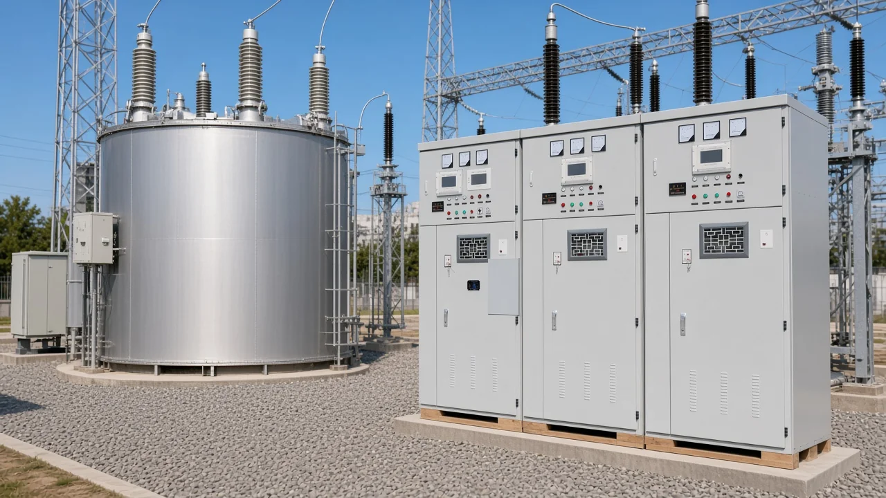
Walk the gravel with the load in mind, not with the nameplate word reactor. If the bus is already making vars, the reactor bay is the parallel device. If the bus is eating vars, the gray cabinet is the parallel device.
A shunt reactor absorbs vars and a shunt capacitor bank supplies them
The bank supplies vars and can raise voltage; the shunt reactor absorbs vars and can lower voltage.
Local vars follow the load already on the bus. An inductive load calls for a shunt capacitor. A capacitive load calls for a shunt reactor.
A continuing-education note on reactive power draws that split, and it treats the reactor as one winding rather than a two-winding transformer, in Fundamentals of reactive power and voltage regulation.
A shunt capacitor bank ties in parallel and feeds vars toward motors and transformers, so source current is less lagging and bus voltage can rise. A shunt reactor bank ties in parallel too, but the current it draws is inductive, so it soaks up vars and voltage can fall. Same bus connection, opposite var sign.
| Device | Var direction | Bus that calls for it | Voltage tendency |
|---|---|---|---|
| Shunt reactor | Absorbs vars | Light line or cable that is producing vars | Can hold voltage down |
| Shunt capacitor bank | Supplies vars | Heavy lagging motors and transformers | Can raise voltage |
Teaching write-ups sometimes park the reactor only on long extra-high-voltage lines, and sometimes say a capacitor can lift voltage at light load. Read the bus. If the bus is already producing vars, more capacitors push the voltage the wrong way.
Procurement still hears the reversed story: reactors to raise a sag, capacitors to pull a rise back down. Field replies that stick put capacitors with a rising tendency and shunt inductors with a falling tendency. Hold that order before any cabinet quote.
A light capacitive bus is the shunt reactor case
Use the shunt reactor when line or cable charging is producing vars and the voltage is rising.
At light load, line or cable capacitance is no longer covered by inductive demand. Charging current makes capacitive vars, and voltage at the receiving end rises. That rise is the Ferranti effect, an end-of-line voltage rise, and the shunt reactor is what absorbs those vars.
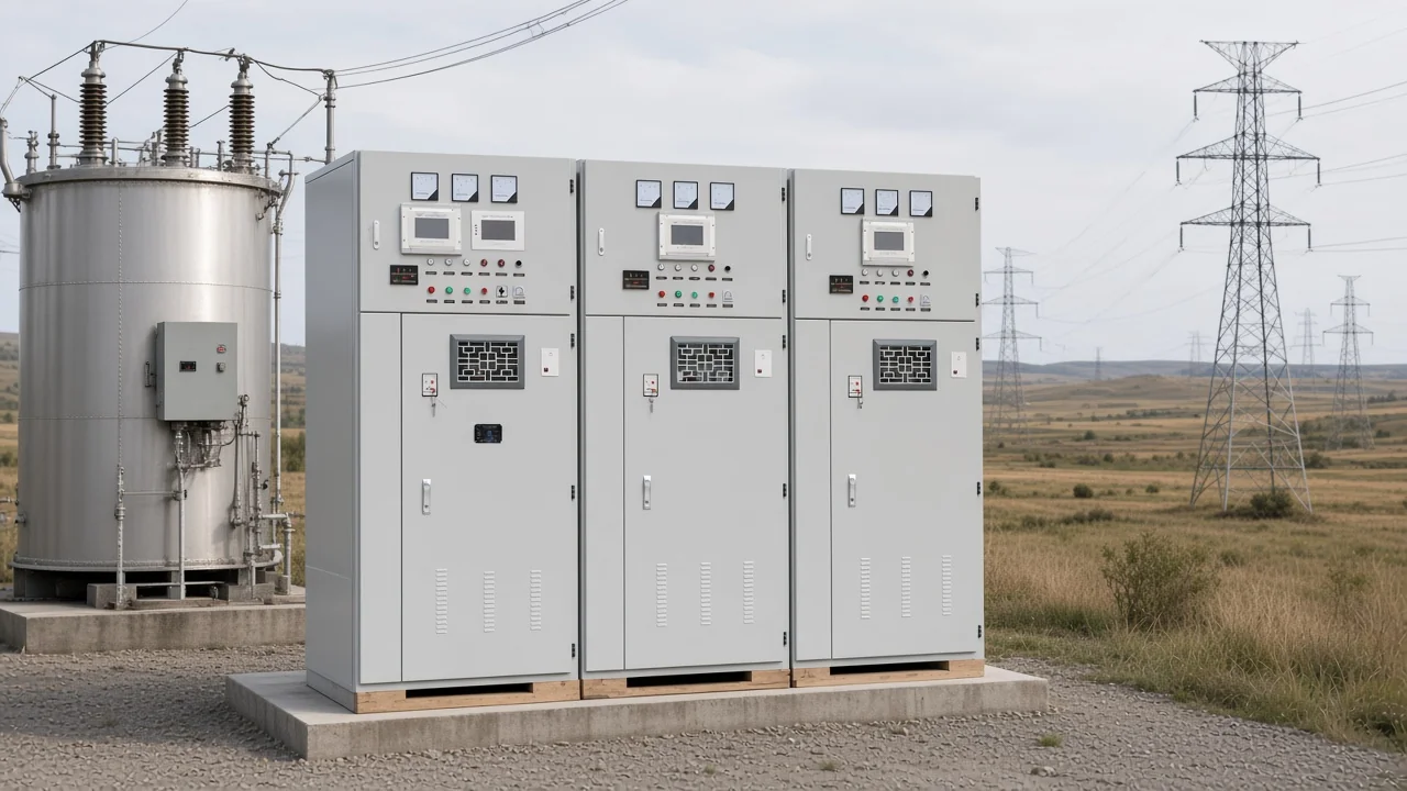
Think of a feeder built for a full shift and left almost idle overnight, or a cable whose charging exceeds the load that remains. The reactor belongs on that bus for those hours. It does not belong there because a cubicle door already says reactor.
Closing a shunt reactor drives an inrush that carries a DC offset. Opening can chop current before a natural zero. A reactor left on a de-energized line beside an energized line can resonate with the capacitance between those lines.
Those stresses belong to the reactor step, after the var decision is already made.
A fixed reactor, a switched reactor, and a variable reactor are different ways to meter that absorption. The buying split here is still whether the bus needs absorption at all. Sizing that step is a study, not a slogan about a voltage class.
A heavy lagging bus is the shunt capacitor bank case
Use the shunt capacitor bank when motors and transformers are consuming vars, and take it off at light load.
Inductive plant load pulls current that lags voltage. A shunt capacitor bank supports voltage and cuts the reactive current the upstream source must carry, which is the plain answer to what do capacitor banks do. The same step is the usual capacitor bank for power factor correction on that lagging load, and it is why buyers search capacitor banks for reactive power compensation.
The what do capacitor banks do note and the capacitor banks for reactive power compensation note stay on that capacitor side of the cluster. A conference paper treats generators and the line alone as unable to hold voltage when load is inductive, and it says voltage control tends to switch the bank on at peak and off at light load, in the Western Protective Relay Conference capacitor paper.
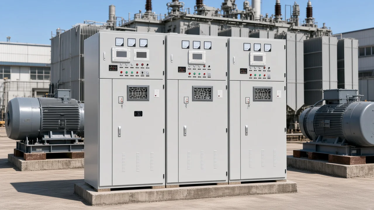
Leave the bank closed after the motors stop and the vars that helped at peak become extra capacitive vars. Voltage climbs. That hour belongs to an open capacitor step, or to a shunt reactor, not to a bank left in.
From the field: Shunt capacitors go on during high inductive loads and come off during low loads, while shunt reactors cover line capacitance when the load is low — source: Mike Holt shunt and series compensation.
A series capacitor is a different pair. It sits in the line and cuts inductive reactance so more power can transfer. It does not decide which parallel device belongs on the bus.
Two bank constructions, fuseless or fused, externally fused or internally fused, are a build detail inside the capacitor choice, not a reason to swap in a shunt reactor.
Time, voltage, reactive power, power factor, current, or a manual switch can all be the control mode that opens and closes the step. The useful habit from voltage control is still on at peak inductive load and off when the load falls. Other modes exist so the step follows the quantity the plant actually watches.
A reactor on the capacitor cans is a series device
That reactor limits inrush or detunes the cans; it is not the shunt reactor on the bus.
People ask why a reactor shows up inside a capacitor bank. That reactor is in series with the cans. It limits inrush, and a detuning reactor shifts the tuned point so the bank is a poorer sink for a harmonic.
The series job is already written in why a reactor is used in a capacitor bank.
A forum post still hands one reactor every inductive task at once: absorb vars, limit fault current, and suppress harmonics. Absorbing line-charging vars can be the shunt reactor. Fault-current limiting and harmonic control are series-reactor work.
The mix is the objection in capacitor bank versus reactor.
On the capacitor groups, series reactors are printed at 4.5–6 percent for 6 kV systems and 12–13 percent for 10 kV systems. Those percents sit on the cans. They are not a shunt-reactor rating, and they do not soak up a light line.
Pointing at that in-line reactor and calling it the bus device sends the quote the wrong way. The series reactor reduces current in its own branch. The shunt reactor is a parallel absorber on the bus.
The shunt capacitor bank is the parallel source. Three devices, three jobs.
Select the HYTBB cabinet only as the shunt capacitor bank
HYTBB is the shunt capacitor cabinet for inductive vars; it is not a shunt reactor, and the cabinet parameter table lists 50 Hz.
The HYTBB medium and high voltage reactive power compensation cabinet is the published shunt capacitor bank for a bus that is consuming vars. The HYTBB cabinet is that medium and high voltage reactive power compensation cabinet, quoted for inductive reactive power.
Rated voltage in the parameter table is 10(6)–35 kV. Rated frequency in that table is 50 Hz. Rated capacity in that table spans 50–20,000 kvar.
The neutral connection is an isolated or non-effective neutral, printed as isolated neutral or non-effective grounding. An overview sentence, kept apart from the table, places the cabinet on systems from 1 kV to 35 kV.
| Printed item | What it covers | What it does not do |
|---|---|---|
| Frequency | 50 Hz | A second frequency is not printed |
| Capacity | 50–20,000 kvar | Not a light-line absorber rating |
| Neutral | Isolated or non-effective neutral | Not a shunt-reactor winding spec |
| Series reactors on the cans | 4.5–6 percent at 6 kV and 12–13 percent at 10 kV | Not the bus shunt reactor |
The covered nameplate still shows the three-bay cabinet quoted as the shunt capacitor bank. Read the doors as that bank, not as a reactor product.
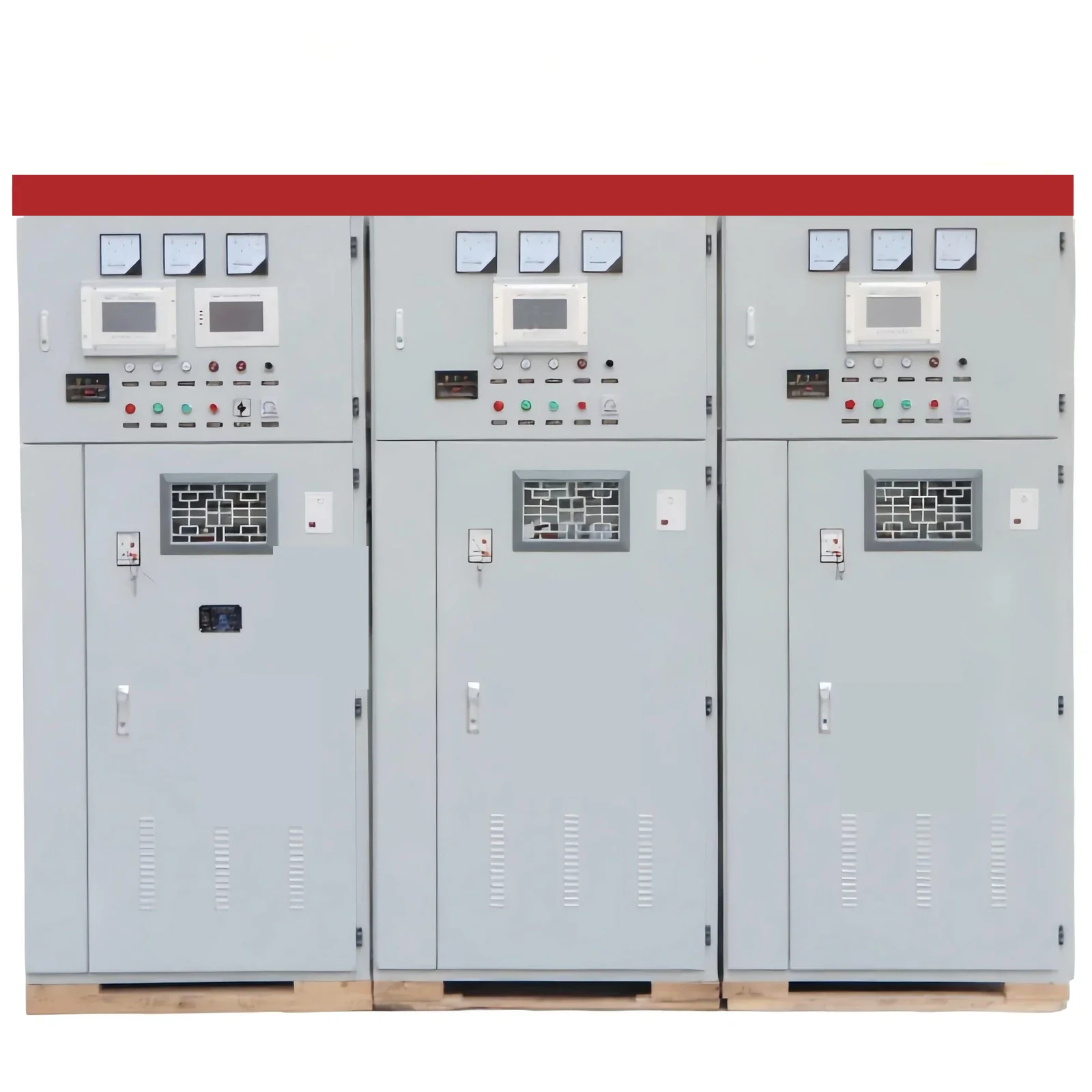
Open the cabinet link only after the bus is confirmed lagging and inductive. A light capacitive bus needs a shunt reactor, and a shunt reactor is not offered for that case.
HYSVC on the high-voltage power factor compensation series pairs a thyristor-controlled reactor plus capacitor branches for impact loads such as arc furnaces, rolling mills, and mining equipment. HYSVC is not titled a shunt reactor.
Discharge wording prints residual voltage below 50 V within three minutes, and a second line prints residual voltage below 50 V within five minutes. Both times are printed. Neither replaces the other.
The stated outcome is power factor up to 0.95 or higher, with line current down 10–20 percent. That wording is the cabinet statement of power factor and line current.
Operating conditions print ambient from −40 °C to +45 °C, humidity at or below 90 percent at 25 °C, and altitude at or below 4500 m. Long-term operation is printed at 1.0 times rated voltage, with a short-duration withstand up to 1.3 times rated voltage and no duration printed next to that multiple.
Indoor or outdoor installation is printed with those ambient limits. The var job does not change with the room. The job changes with whether the bus is lagging or already capacitive.
Switching rules differ before either device is closed
The two devices are not closed on the same electrical instant, and either step still has to be coordinated with the tap changer and other var controls.
Discuss the shunt reactor at voltage crest, because reactor current lags voltage by a quarter cycle. A discharged capacitor bank is discussed when its voltage already matches the grid, which on a discharged bank is a voltage zero. One close command for both devices ignores that split.
From the field: Closing a shunt reactor draws an inrush with a DC offset, and opening can chop that current — source: IEEE Fort Worth PES shunt capacitor and reactor presentation.
The same presentation names reactor inrush with a DC offset, current chop on opening, and resonance when a reactor sits on a dead line beside a live line. Keep those stresses with the reactor step. Keep the capacitor voltage step and capacitor inrush with the capacitor step.
Neither note is an install procedure for shunting a bank.
Either switched step still has to live with the tap changer, also called an LTC, with generator vars, and with faster neighbors such as an SVC or a STATCOM. Coordination means the steps are not fighting the same bus. It does not invent a new control scheme.
A capacitor step that closes into a light bus fights the reactor you just added for the Ferranti effect. A reactor step left in at peak inductive load fights the shunt capacitor bank you added for the motors. Order the close after the var sign is known, then after the tap changer and the other var controls already on that bus.
FAQs
What is the difference between a shunt reactor and a shunt capacitor bank?
The shunt reactor absorbs vars and can lower a rising light-bus voltage. The shunt capacitor bank supplies vars and can raise voltage on a lagging bus.
When does a light bus call for a shunt reactor instead of a capacitor bank?
Call for the shunt reactor when line or cable charging is producing vars and the Ferranti effect is lifting the end-of-line voltage. A capacitor bank on that bus would add still more capacitive vars.
When does a lagging plant load call for a shunt capacitor bank?
Call for the shunt capacitor bank when motors and transformers are consuming vars at peak, and open it when that load falls away. Leaving it in through the light hours is the voltage climb the reactor case is meant to avoid.
Why is a reactor inside a capacitor bank a different device?
That reactor is in series with the cans to limit inrush or to detune them. It is not the shunt reactor that absorbs line-charging vars.
Does the HYTBB cabinet absorb vars the way a shunt reactor does?
No. The HYTBB cabinet supplies vars for inductive load. It does not absorb the vars of a light capacitive bus.
Can the HYTBB cabinet be specified at 60 Hz?
Rated frequency printed for the HYTBB cabinet is 50 Hz.
What should be checked before either device is switched on a bus?
Check that the close instant matches the device, then check coordination with the tap changer and with any other var control already on the bus. A shunt connection only means the device is parallel to the bus. It is not a procedure for landing the cables.
References
These notes and threads are the outside reading for the var split, the peak-load timing, the switching stresses, and the two forum objections.