
 Zhejiang Hongyan Electric Co., Ltd.





































A reactor is put with a capacitor bank to hold down the switching surge and to keep that bank off a harmonic resonance with the supply. Plant teams who look up why use reactor in capacitor bank are separating those two jobs before they pick a coil. The sections below follow the surge, the magnification, the tune, and the series unit that matches a reactor placed with the capacitors.
Closing an uncharged step is the harsh moment. After that, the same coil still has a job while the drives keep running.
What Closing an Uncharged Bank Does
An uncharged bank draws a short, high-frequency current at the moment it closes.
Engineers call that pulse the inrush current: the switching inrush on an uncharged bank.
Picture a step that has been open long enough to sit near zero volts. The bus is at full voltage. When the contactor closes, the difference appears across the capacitors in one instant.
Charge has to rush in to catch up. For that brief interval the branch behaves like a short, and the current is a fast pulse rather than the steady reactive current the bank will draw a cycle later.
Fuses, contactor tips, and the capacitor elements all sit in that path. A pulse that the steady rating never shows can still pit a contact or open a fuse that looked healthy on a meter.
Back-to-back steps make the pulse sharper. One step is already charged, the next one is not, and the charged step dumps into the empty one through whatever impedance sits between them.
Buswork, fuses, and a few feet of cable are a small impedance. Without something inductive in that path, the pulse frequency climbs and the peak climbs with it.
How Series Inductance Cuts the Switching Surge
A series reactor raises impedance while that high-frequency current is flowing.
Put in the capacitor path, a series reactor limits that surge.
Inductive reactance grows with frequency. The closing pulse is the high-frequency event, so the coil looks large to the pulse and ordinary to the power-frequency current that follows.
On a single isolated step the system inductance already does some of this work. The hard case is two or more steps on one bus, where the path between them is short.
A series coil in each step lengthens that path electrically. The pulse still happens. Its peak and its frequency both come down, which is what the switch and the fuses actually feel.
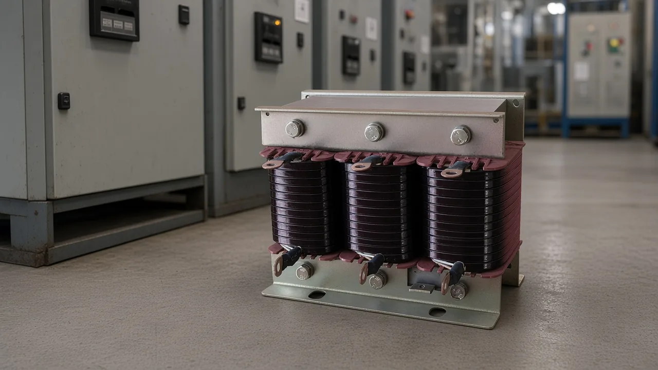
Pre-insertion resistors and controlled closing are other ways to soften the same moment. A series coil stays in the circuit after the contacts finish moving, which is why it can do a second job once the bank is on.
From the field: A power-factor cabinet with no series inductors drew a forum remark that commercial banks usually put reactors in series with the capacitors — the source of that remark was harmonic current through the capacitors, and a later note tied the same worry to switching inrush.
The remark matches the two jobs. Harmonic current and the closing pulse are both extra current in the capacitors. Reactance in series speaks to both, which is why a coil sized only for a tiny surge is not the same object as a coil sized to move resonance.
Where the Bank Can Magnify a Harmonic
Supply inductance plus the bank can amplify a harmonic that drives already produce.
That rise is harmonic resonance on the same bus.
Drives, rectifiers, and other electronic loads already push current in lumps. A plain capacitor bank does not create those lumps. It can make them larger when its capacitance and the supply inductance land near one of those lump frequencies.
At that point the bank and the transformer form a resonant pair. Current at the matching harmonic rises in the capacitors, the transformer, and the cables, even though the drives did not suddenly get larger.
Heat in the capacitors is the usual clue. Fuses that fatigue, a humming transformer, and a waveform that looks worse after the bank is switched in all point the same way.
Parallel resonance at the bus and the series tune of one branch are not the same event. The bus can still show a voltage peak near a parallel resonance while a series branch has its own lower tune.
Moving the bank, or changing how much capacitance is online, shifts the pair. Neither move tells you which harmonic the drives actually produce. A coil in series changes the branch on purpose instead of hoping the pair misses.
How Tuning Keeps the Branch Capacitive at Power Frequency
The branch still supplies reactive power at power frequency and turns inductive at the harmonics.
The practical name for that split is tuning below the lowest harmonic.
At power frequency the capacitor reactance is still the larger term, so the step keeps correcting power factor. At the higher frequencies the coil's reactance has grown, the branch looks inductive, and it stops inviting the harmonic current to ring.
A detuned reactor in capacitor bank service is this coil. It is sized so the series tune sits below the lowest harmonic the plant cares about, not on top of that harmonic.
Sitting on the harmonic would be a filter. A detuned branch may still draw some harmonic current. It is not built as a sink with a stated absorption target for one order, and treating it as one leads to the wrong thermal rating.
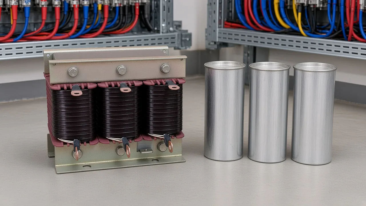
A small air-core coil wound only to blunt the closing pulse usually does not move that tune. A detuning coil, with an iron core and a real inductance, does limit the closing pulse as a side effect of being in series.
So the buying question is which job dominates. If the plant only needs the pulse blunted and the bus is quiet, a tiny series impedance may be enough. If drives are on the same bus, the coil has to be the detuning size or the bank will still magnify.
A series reactor in capacitor bank duty can mean either of two jobs, and the jobs are easy to mix. One job limits the slam when the step closes. The other keeps the step from singing with the supply.
Which Series Reactor Fit to Select for That Job
The series tuning reactor is the published fit for a reactor in series with capacitors. CKS-G is the dry-type air-cooled build, and CKS-S is the epoxy-cast build.
Place either build in series with the capacitors so the branch can still correct power factor at power frequency and look inductive once the frequency rises.
The series tuning reactor is a harmonic-suppression circuit: the resonant point of the branch is shifted below the lowest harmonic order on the system. When the tune targets the fifth, the branch can take up a share of harmonic current. That share is a catalog description, not a measurement from a named plant.
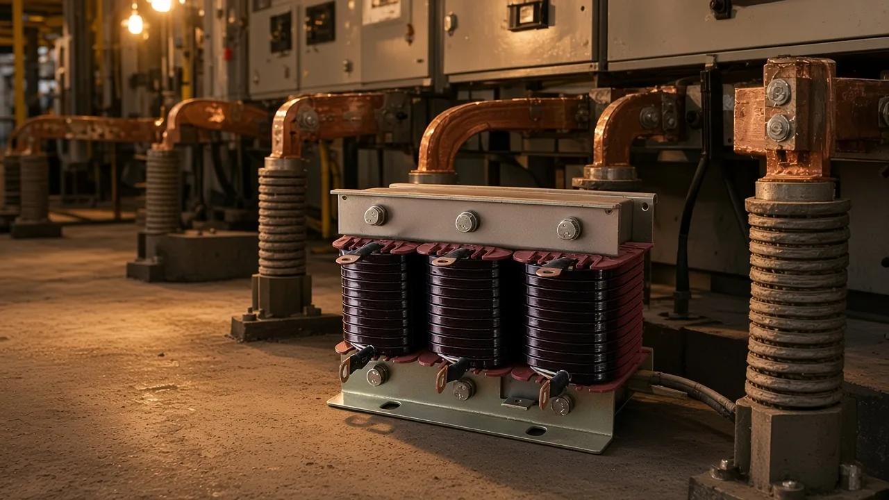
The published match for that series job is the Series Reactors (Tuning Reactors). The family of compensation equipment around these banks is the high-voltage power factor compensation series.
What the closing pulse looks like on a larger bank is a separate discussion in capacitor bank switching transients. The coil choice here is about which published reactor belongs in series, not about how to lay out a whole bank.
| Job on the bank | What the coil is doing | Published fit |
|---|---|---|
| Closing surge | Raises impedance for the high-frequency pulse | Same series path; a detuning coil also limits the pulse |
| Detune | Stays capacitive at power frequency and inductive at harmonics | Series Reactors (Tuning Reactors), CKS-G or CKS-S |
| Absorb one harmonic | Forms an LC branch at a designated frequency | Filter reactor, not the default |
| Medium or high voltage | Series with the bank for inrush and amplification control | CKSC, not the low-voltage tuning unit |
Printed ratings for the series tuning reactor belong in one scan, not in a guessed plant percent.
| Item | Printed value |
|---|---|
| Rated voltage | 230V to 690V |
| Rated frequency | 50Hz |
| Detuning rate options | 5.67%, 6%, 7%, 14% |
| Dielectric test | 3kV for 60 seconds |
| Inductance tolerance | 0 to +5% |
| Ambient temperature | -10°C to +40°C |
| Altitude | 2000m maximum |
| Maximum humidity | 95% |
| Noise | below 65 dB |
| Linear current | 1.35 In continuous |
| Winding protection | 125°C |
| Insulation class | F or H |
| Enclosure | IP00, indoor |
| Listed standards | EN 60076-6 and EN 61558-2-20 |
| Harmonic share in the description | about 30% to 50% when the tune targets the fifth |
The detuning list is a set of options. The specification table does not pick one percent for every plant, and it does not state a resonance frequency in hertz.
The frequency line is fifty hertz as printed. The specification table does not print a sixty-hertz rating, so none is assumed. It also does not name a grid-code or listing mark.
Model letters include a kvar placeholder and a voltage-drop percent. They are blanks to fill from the project, not a catalog kvar for a stock bank.
Temperature protection sits in the winding. Cooling is natural air. Terminals are copper.
The specification notes low-loss silicon steel and linearity, which fit a detuning coil that must not saturate on the harmonic current it still carries.
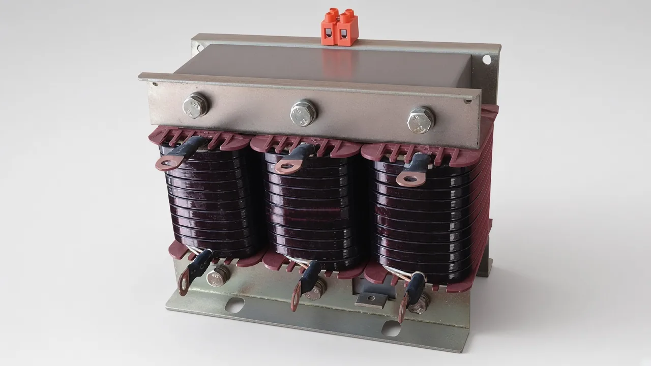
Use this series unit when the bank is in the printed voltage window and the job is a reactor in series with the capacitors. If the bus is medium or high voltage, or the cabinet is a tuned filter, the next section is the split.
When the Job Is a Filter Branch or a Higher-Voltage Bank
A filter reactor absorbs a chosen harmonic, and CKSC is the series unit for medium and high voltage.
Call that split a filter branch or iron-core unit.
Filter reactors in the LKSG series are connected in series with power capacitors to form LC branches inside a filtering cabinet. Their job is inductive impedance at a designated harmonic so the branch soaks up local harmonic current instead of only sliding the tune downward.
Here the fit changes from the detuning list above. The filter reactors carry their own current span, voltage list, and matching capacitor span. Those spans are not a default size for the tuning reactor.
On a medium- or high-voltage bank, CKSC sits in series with the capacitors to limit switching inrush and to control harmonic amplification. Dry-type epoxy cast and oil-immersed builds are both named, chosen from voltage, capacitor capacity, reactance ratio, and where the unit will stand.
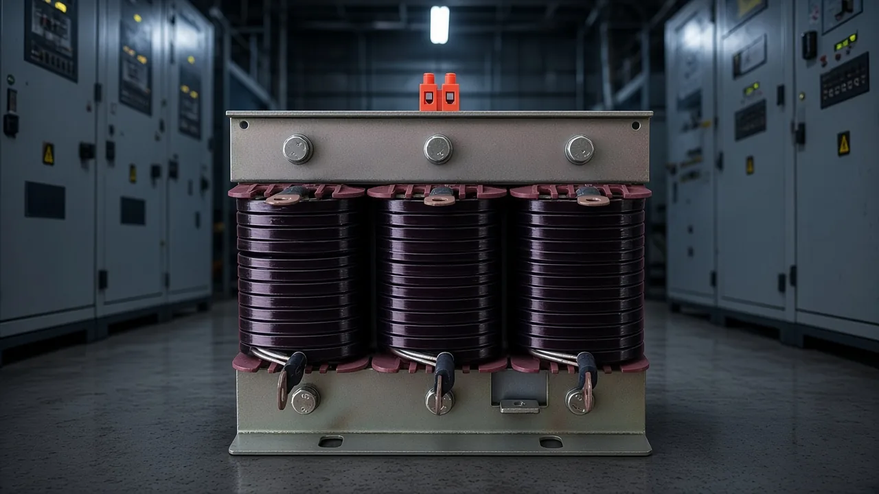
Open the CKSC high-voltage iron-core series reactor when the bank is above the low-voltage tuning range. It is not a substitute name for the CKS-G or CKS-S tuning reactor.
Three questions sort the paperwork.
Is the coil only blunting a closing pulse, or is it also moving resonance? Is the branch supposed to absorb a designated harmonic, or only to stop amplifying one?
Is the bank inside the low-voltage window printed for the tuning reactor, or is it a medium- or high-voltage step?
Answer those from the one-line diagram and a harmonic snapshot, then open the matching page. A single percent copied from a neighboring plant is not one of the printed options until it is on the series-reactor list.
FAQ
Why are reactors used in capacitor banks?
Two jobs share the series path. The coil limits the high-frequency pulse at closing, and a detuning size also slides resonance below the harmonics the drives produce.
What is the purpose of a shunt reactor beside a capacitor bank?
A shunt reactor is a different device. It absorbs reactive power and is the tool people discuss when voltage is already high. It is not the coil in series with a capacitor step.
What are common causes of capacitor banks failing when harmonics are present?
The bank does not invent the harmonics. It can amplify them when it resonates with the supply, and the extra current heats the elements and tires the fuses.
Does a small inrush reactor also detune the bank?
Usually no. A few turns meant only to blunt the closing pulse leave the tune near the system inductance. A detuning coil limits the pulse and moves the tune.
What does a series reactor change at power frequency?
The capacitor term still dominates, so the step keeps supplying reactive power. The coil's extra reactance shows up once the frequency rises into the harmonics.
When is a filter reactor the different fit?
Use it when the branch is supposed to absorb current at a designated harmonic inside a filter cabinet. The tuning reactor's job is to slide resonance down, not to be that sink.
Why does the series page print standards other than a grid-code listing?
The specification table names the standards printed for that reactor. A listing mark that is absent from the table is not added from a neighboring catalog.
References
- Why reactors are used with capacitor banks explains the closing surge and why series inductance limits it.
- MAAC shunt capacitor chapter covers back-to-back inrush and series reactors as one way to deal with resonance.
- Capacitor-bank harmonic resonance case note separates a detuned branch from a harmonic filter.
- Power-factor cabinet thread on series inductors records the field worry when a cabinet has capacitors and no series reactors.