
 Zhejiang Hongyan Electric Co., Ltd.





































Capacitor bank switching transients in power systems are the short electrical events that appear when a shunt bank or step is closed or opened—closing drives energizing inrush and a ring-wave overvoltage; opening can leave trapped charge and, on restrike, much higher peaks—and those events decide which mitigation and study evidence belong on the package before energization. What follows maps closing, opening, field cues, the reactor / pre-insertion / capacitor-rated switch matrix, the study gate, and when series tuning reactors fit the branch. A shunt bank is not a battery energy-storage substitute.
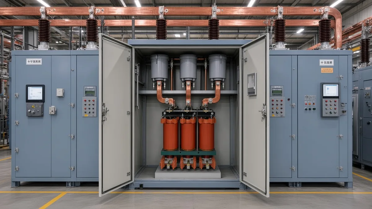
What Capacitor Bank Switching Transients Include on a System Checklist
Switching concerns split into closing inrush, opening restrike paths, voltage magnification at lower-voltage capacitors, and related outrush / TRV items—closing and opening are the buyer’s first decisions.
A shunt capacitor bank cannot change voltage instantly, so every close or open launches an LC oscillation that stresses the switch and the units. Tutorial case work groups the same families as energization inrush, bank-to-bank exchange, outrush into a nearby fault, magnification at a smaller downstream bank, and breaker transient recovery voltage (TRV).
Closing is the everyday entry: the bank looks like a short for an instant, the bus dips, then a decaying ring wave appears. Opening is the quieter twin that still decides switch class, because trapped charge and restrike set the recovery the interrupter must survive.
If the plant already has LV power-factor capacitors under a larger upstream bank, put voltage magnification on the same checklist when that upstream bank switches and the natural frequencies line up. Outrush and TRV stay study cases rather than nameplate slogans; they belong beside the close/open pair once topology is known.
Multi-step neighbour loops that already share an energized bank on the bus are covered in the live back-to-back switching guide. Wider HV compensation hardware still routes through the parent HV PF compensation hub once voltage class and reactor fit are clear.
Closing Inrush on an Isolated Bank: Voltage Step, Ring Wave, and Switch Stress
Closing a discharged bank forces a voltage step and a decaying ring wave; under typical damping, practical peaks often sit near 1.2–1.8 per unit at a few hundred to about 1000 Hz.
Isolated / single-bank energization means the first (or only) bank closes against source inductance, not against a live neighbour. At contact make the capacitors draw energizing inrush while bus voltage steps toward the capacitor voltage and then rings as the LC circuit damps.
Theoretical undamped peaks can reach roughly two per unit. Utility distribution and transmission examples with practical damping more often land in that 1.2–1.8 pu band at roughly 300–1000 Hz, which is still enough to stress closing contacts and disturb sensitive loads.
Plant symptoms trail the waveform: VFD DC-bus overvoltage trips, UPS transfers, and surge-protective-device counts that cluster at known switching times. Distant events attenuate, so a mild RMS lift after the bank stays in can still be the local signature of capacitor bank switching transients.
| Cue on close | What the waveform / site shows | What is stressed first | First mitigation question |
|---|---|---|---|
| Voltage step + ring wave | Sudden step, then a few-hundred-Hz to ~1–2 kHz ring | Switch making duty; nearby electronics | Series L, pre-insertion, or controlled closing? |
| Practical overvoltage band | Often ~1.2–1.8 pu under typical damping | Insulation and arresters on the bus | Is the switch rated for capacitive making? |
| Theoretical ceiling | Approaches ~2 pu undamped | Worst closing angle cases | Does the study cover closing angle statistics? |
| Load side | VFD / UPS / SPD complaints timed with bank close | Process equipment, not only the bank | Is remote overvoltage the real complaint, or local inrush? |
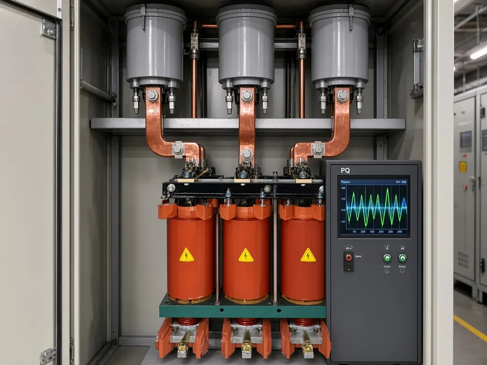
Opening, Trapped Charge, and Capacitor Switch Restrike Overvoltage
A clean open leaves trapped charge; grounded-wye TRV can reach about two per unit half a cycle later, and a restrike can push theoretical peaks toward about three per unit.
Capacitive interruption typically clears near a voltage peak, so about 1.0 pu stays on the bank as trapped charge. Half a cycle later the source has swung the other way, and the recovery voltage across a grounded-wye switch sits near two per unit.
Switch restrike is dielectric failure across the opening gap after current interruption—the arc that re-strikes while the switch is trying to stay open. On grounded-wye banks, a worst-case restrike can drive theoretical overvoltages toward about three per unit; ungrounded banks can see steeper recovery paths and multi-restrike escalation.
Field investigations of vacuum-switch multiple restrike on ungrounded utility banks show customer ASD trips and MOV stress when the interrupter cannot hold the recovery. Arresters on the capacitor side of the switch and devices chosen to keep restrike probability low are the opening-side companions to closing reactors.
| Cue on open | What appears | What is stressed | First mitigation question |
|---|---|---|---|
| Clean open | ~1 pu trapped charge on the bank | Discharge / reclose timing | Has trapped charge decayed before reclose? |
| Grounded-wye TRV | ~2 pu across the switch ~½ cycle later | Interrupter dielectric | Capacitor-rated breaking duty? |
| Restrike | Theoretical peaks toward ~3 pu (grounded-wye) | Switch, MOV, capacitor units | Minimize restrike probability; MOV location? |
| Ungrounded bank | Higher recovery / multi-restrike paths | Same plus phase interaction | Grounding and switch class reviewed together? |
How to Recognise Capacitor Switching on Drawings, Nameplates, and PQ Captures
Look for a step + ring + small RMS lift after close, multi-step cues on the single-line diagram, and load symptoms such as VFD or UPS trips—multi-step bank-to-bank duty depth belongs to the live back-to-back article.
Tip: If the waveform shows a step, a ring, and a small voltage lift after the event, treat capacitor energizing as a prime suspect — field PQ signature.
On the single-line diagram, count how many capacitor branches share one bus run and whether any step can close while neighbours stay live. Nameplates that print group, step, or stage switching mark automatic multi-step cabinets; those layouts need the neighbour-loop question answered before ordering another stage.
PQ captures usually show an initial voltage step toward the capacitor voltage, a recovery oscillation from a few hundred hertz into the low-kilohertz range, and often a small RMS rise once the bank remains connected. Predictable utility or controller switching times and clustered SPD counts strengthen the same reading.
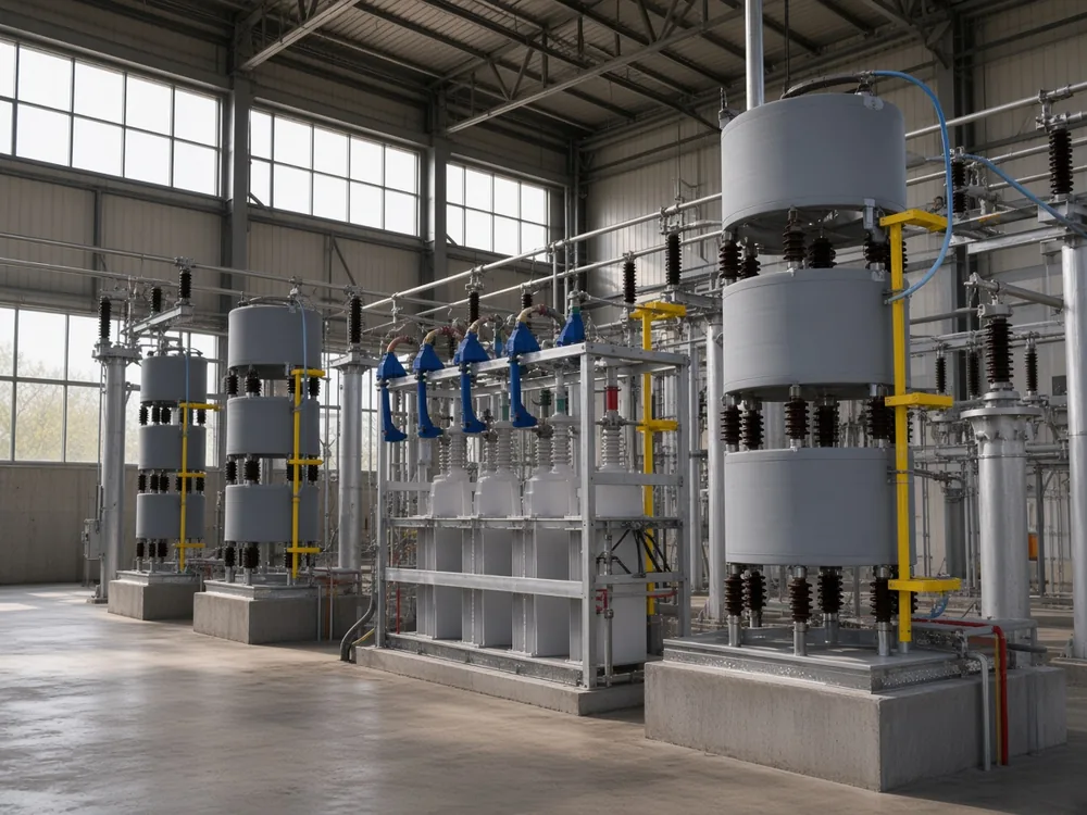
Specifying Reactors, Pre-Insertion, and Capacitor-Rated Switches by Duty
Match series inductance, pre-insertion, controlled closing, and withstand ratings to the duty—reactors control current (and often switch duty), not every remote overvoltage. Controlled closing angle detail sits in the live PoW article.
The established mitigation set is series / current-limiting reactors, a pre-insertion resistor / inductor, point-on-wave / synchronous closing, and equipment ratings that withstand the transient. Which item dominates depends on whether the pain is local inrush current, remote overvoltage, or opening restrike.
Important: A series reactor is for current (and often switch duty) control, not a free substitute for every overvoltage problem, and its placement can raise TRV — reactor location and study case.
| Mitigation | What it mainly changes | When it is usually required | Honesty limit |
|---|---|---|---|
| Series / current-limiting reactor | Peak and frequency of inrush (especially parallel-bank duty) | Short inter-bank loops; switch making stress | Fixed L may do little for remote overvoltage; inductor between breaker and bank can worsen TRV |
| Pre-insertion resistor / inductor | Only the closing make interval, then bypassed | Existing banks where permanent reactance costs too much compensation | No help after bypass; mechanism inside the switch |
| Point-on-wave / synchronous closing | Closing angle so voltage already nearly matches | Closing-voltage transient is the dominant complaint | Timing depth lives in the live PoW closing article |
| Capacitor-duty switch / breaker | Withstand making/breaking capacitive duty | Any bank whose study shows high making or restrike stress | Survives the duty; does not remove the physics |
Point-on-wave / synchronous closing can greatly reduce energizing voltage transients when timed correctly; the timing tutorial itself is not repeated here. Practitioners also treat series inductance as either a small inrush reactor, a detuned / tuning reactor, or both—match the catalogue page to the job rather than assuming one coil answers every transient.
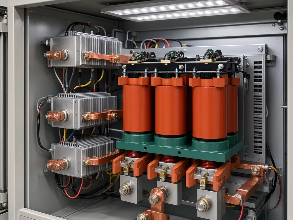
What a Transient Study and Manufacturer Package Must Show Before Energization
Ask for closing / opening (and parallel-bank) cases, magnification checks when LV capacitors exist, device ratings versus the transient, and discharge / reclose rules before the first close.
A transient study (EMT) is the time-domain package that proves the bank is safe to energize under the topologies you actually have. New installations, multi-step cabinets on one bus, weak sources, and sites with downstream LV capacitors are the usual triggers to commission it.
Ask the package to show, at minimum:
- energization of each bank or step, including statistical closing angles where the study method supports them;
- opening / TRV and restrike exposure for the chosen switch class and bank grounding;
- parallel-bank or back-to-back cases when neighbours share a bus;
- voltage magnification when a larger upstream bank can ring a smaller plant bank;
- outrush into nearby faults when topology places the bank near likely fault points;
- comparison of switch, fuse, CT, and arrester ratings to the predicted peaks and frequencies;
- discharge design and reclose wait so trapped charge has decayed—planning practice often cites on the order of five minutes, and discharge rules must match the manufacturer design rather than a habit.
Skipping that gate leaves commissioning to discover what the waveform already knew.
When to Select Series Tuning Reactors With the Capacitor Branch
Select the CKS series tuning reactors when the branch needs a series / detuned reactor for resonance and harmonic control; use related CKSC wording only when the enquiry is MV/HV inrush limiting. CKS listings do not publish inrush kiloampere ratings for that MV/HV framing. A series reactor capacitor bank package still needs the study, pre-insertion, and switch-rating gates above.
Series Reactors (Tuning Reactors)—CKS-G / CKS-S—are series tuning reactors installed with a capacitor bank to form a harmonic-suppression / detuned circuit. They shift resonant frequency below the lowest harmonic order, stay capacitive at power frequency for power-factor improvement, and become inductive at harmonic frequencies to limit resonance and harmonic amplification.
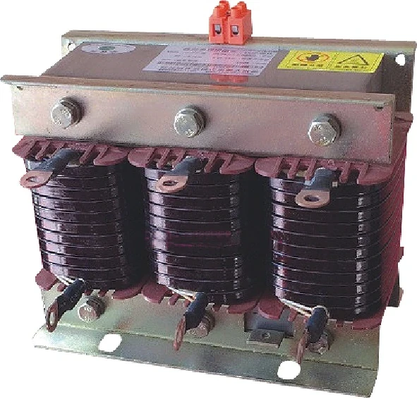
CKS published envelope: rated voltage 230 V–690 V, 50 Hz, detuning options 5.67% / 6% / 7% / 14%, linear current 1.35 In continuous, about 30%–50% harmonic-current absorption when properly tuned, dielectric 3 kV / 60 s, ambient −10°C ~ +40°C, altitude ≤2000 m. Buyers select by rated capacity, system voltage, detuning factor, and phase type.
That envelope is LV detuned / harmonic-suppression framed. MV/HV “limit switching inrush” language belongs only to the related CKSC HV series reactor.
Review the series tuning reactors page with system voltage, capacitor kvar, and detuning target in hand, then confirm whether the duty also needs a study, pre-insertion, or a capacitor-duty switch / breaker. Series L on the branch is still not a substitute for those other gates.
FAQ
What causes capacitor bank switching transients in power systems?
Capacitor voltage cannot jump, so closing or opening a shunt bank or step forces an LC oscillation—energizing inrush on close, trapped-charge recovery and possible restrike on open, plus magnification or outrush when topology couples other banks or faults.
What happens when a capacitor bank is switched on?
The bus sees a voltage step and a decaying ring wave while charging current rushes in; under typical damping the overvoltage often lands near 1.2–1.8 per unit at a few hundred to about 1000 Hz, and sensitive loads may trip even when the bank itself survives.
What is the difference between single-bank and back-to-back capacitor switching?
- Single-bank / isolated: the step closes mainly against source inductance.
- Back-to-back switching: a neighbour bank already energized on that bus fills the new step through the short local loop.
- Duty calculation depth for that neighbour loop lives in the live back-to-back switching guide.
How do you mitigate capacitor bank switching transients?
- Specify series inductance when inrush current and switch making stress dominate.
- Use a pre-insertion resistor / inductor when only the make interval needs damping.
- Use point-on-wave / synchronous closing when closing-voltage transient is the main complaint—timing detail sits in the PoW sibling.
- Choose a capacitor-duty switch / breaker and arresters that withstand the duty the study predicts.
What is a capacitor bank switch restrike?
It is dielectric failure across the opening gap after capacitive current interruption, re-applying voltage to a charged bank; grounded-wye theoretical peaks can approach about three per unit, and ungrounded banks can escalate further.
How can you identify capacitor switching on a power-quality waveform?
Look for a sudden voltage step, a low-frequency ring wave, and often a small RMS voltage rise after the bank stays in, especially when the timestamp matches known utility or controller switching and loads such as VFDs or UPS units react.
Why use a series reactor with a capacitor bank?
Series inductance can limit inrush current, shape switch duty, and/or detune the branch against harmonic resonance; LV detuned series tuning reactors answer the harmonic-suppression framing, while MV/HV inrush-limiting wording belongs to the related CKSC page.
When is a transient study required before energizing a capacitor bank?
Commission one for new banks, parallel steps on one bus, weak systems, magnification risk when LV capacitors sit downstream, or whenever switch and arrester ratings must be proven against predicted peaks before the first close.
References
- General Reference – Utility Capacitor Switching (Electrotek / PQSoft PQS0302) — Power Quality Blog
- Shunt Capacitor Bank Switching Transients: A Tutorial and Case Study (MTU / NSP) — Michigan Technological University
- Evaluation of Capacitor Bank Switch Restrikes (Electrotek / PQSoft PQS0606) — Power Quality Blog
- How to identify Capacitor switching transients? — Voltage Disturbance
- Utility Capacitor Bank Switch Failure Investigation — EnerNex
- Power factor correction capacitor bank — Physics Forums