
 Zhejiang Hongyan Electric Co., Ltd.





































Point-on-wave switching closes each capacitor-bank pole when the AC bus voltage nearly matches the voltage already on the capacitor terminals, so the instantaneous voltage difference—and the point on wave switching for capacitor banks inrush spike—stays as small as the breaker and control can make it. This article explains how that timing works for discharged and charged banks, why back-to-back steps still hurt, how controlled switching of capacitor banks compares with reactors and pre-insertion methods, and what to check when you specify a medium- or high-voltage shunt bank package.
SEO title: Point on Wave Switching for Capacitor Banks Explained
Meta description: Learn how point-on-wave switching limits capacitor-bank inrush, handles residual charge and back-to-back cases, and when reactors or HV bank design matter.
Focus keyword: point on wave switching for capacitor banks
Slug: point-on-wave-switching-for-capacitor-banks
Canonical: https://chynele.com/blog/point-on-wave-switching-for-capacitor-banks/
Draft Agent: CHYN-DRF-AGT-20260907-01
Humanizer self-audit: PASS — removed mirrored definition loops; study percentages kept study-scoped; no Claim IDs in body; second pass trimmed filler on compare and breaker sections.
What Point-on-Wave Switching Means for Capacitor Banks
Point-on-wave (PoW) switching—also called controlled switching or synchronous closing—means an intelligent controller delays a random close command until each independent pole can make contact near a chosen angle on the AC voltage wave.
Capacitors resist sudden voltage change. If the bus sits near a voltage peak while the bank terminals sit near zero, closing forces a large ΔV across the capacitors and a fast charging current.
PoW logic measures the live wave, predicts where voltage will be when the mechanism actually finishes closing, and issues the coil command early enough to land on the target angle. Utility and industrial practice describe the same physics whether the hardware is a high-voltage breaker with a controlled-switching device or a medium-voltage bank controller tied to a capacitive-duty interrupter.
On a fully discharged, wye-grounded bank the usual target is a voltage zero-crossing on each phase. On a bank opened moments earlier, the target may sit near a voltage peak—or somewhere between—while trapped charge decays. The label “zero-cross switching” is therefore only one special case of PoW, not the whole method.
Why Capacitor Bank Energization Creates Inrush and Voltage Steps
Random energization can force a large voltage step onto the capacitors and launch a short high-frequency inrush before the current settles to the steady reactive value.
At the make instant, current follows the capacitor relation: it rises with how quickly terminal voltage is forced to change. Source impedance, bank size, the switching angle, residual charge, and whether another bank is already online all change the peak.
Educational treatments often place single-bank peaks at many times rated current; field discussions on engineering forums describe still higher multiples when banks share a stiff bus. The voltage at the connection point can dip, overshoot, and ring while the LC circuit damps out—sometimes enough to disturb sensitive loads or stress nearby insulation.
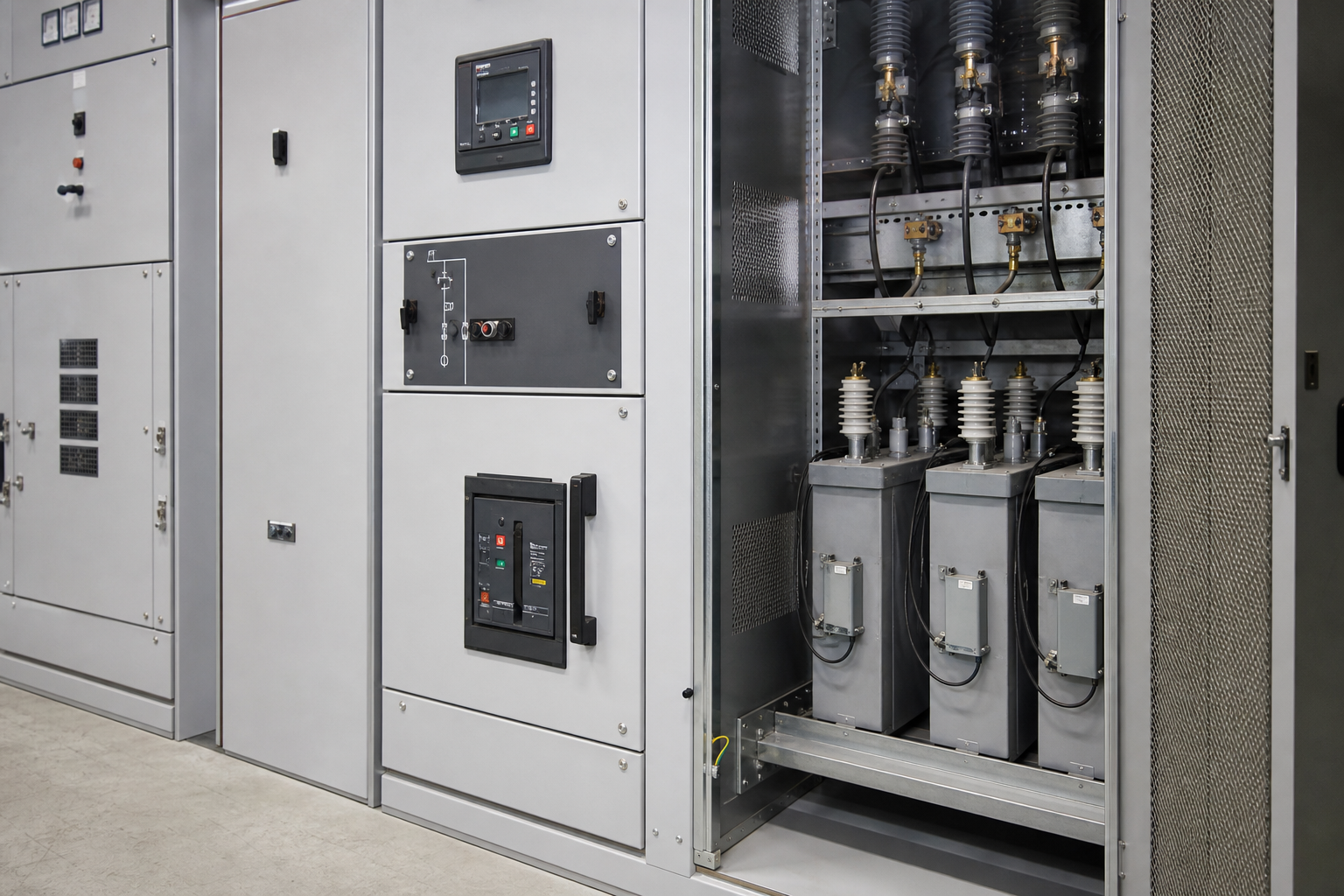
Automatic power-factor stages make capacitor bank inrush current an operations problem, not only a lab waveform. A controller that adds and sheds steps across a shift multiplies energization events. Plants that chase a moving motor load without inrush control often discover the pain as contact wear, fuse nuisance, or bus complaints.
Tip: Excess capacitance and a leading power factor can drive large inrush currents during capacitor switching events, so banks still need sequencing and inrush discipline even when PoW timing is on the agenda (Physics Forums PFC capacitor bank thread).
Zero-Voltage Closing Versus Residual Charge Targets
Discharged banks usually target a close near voltage zero; banks that still hold charge need a different target so the controller matches residual voltage instead of assuming zero volts.
When capacitive current interrupts at current zero, voltage on the bank is near a peak. The capacitors do not “empty” at the open command.
Discharge resistors, reactors, or other bleed paths bring voltage down over minutes in many designs—long enough that a fast reclose is still a charged-bank close. Advanced controlled-switching notes treat the optimum angle as dynamic: shortly after open it may sit near peak voltage; after full discharge it returns toward zero-crossing.
| Capacitor charge state when close is requested | Typical PoW close target | Reader takeaway |
|---|---|---|
| Fully discharged | Near voltage zero-cross | Minimizes initial ΔV for the classic case |
| Fully charged (just opened) | Near voltage peak | Matches trapped charge polarity and magnitude |
| Partially discharged | Intermediate angle on the wave | Controller must track decay, not assume zero |
Blocking timers that simply forbid reclose for a fixed interval help when residual voltage is unknown. They are blunt instruments compared with measuring or modeling residual state, but they beat advertising “zero-cross” while slamming a charged bank at the wrong angle.
Back-to-Back Banks and Other High-Stress Switching Cases
Energizing a bank while another bank or step is already connected on the same bus—back-to-back capacitor switching—can create a local high-frequency surge even when each nameplate rating looks modest.
The already-energized bank becomes a stiff voltage source with little impedance between neighbors. Outrush from the live bank and inrush into the closing bank can dwarf single-bank energization.
Forum engineers describing large power-factor banks return to this point repeatedly: limiters, series reactors, and operating restrictions matter as much as relay settings. CIGRE survey summaries of shunt capacitor switching likewise show frequent daily operations on many installations, which multiplies exposure to making and breaking stress over equipment life.
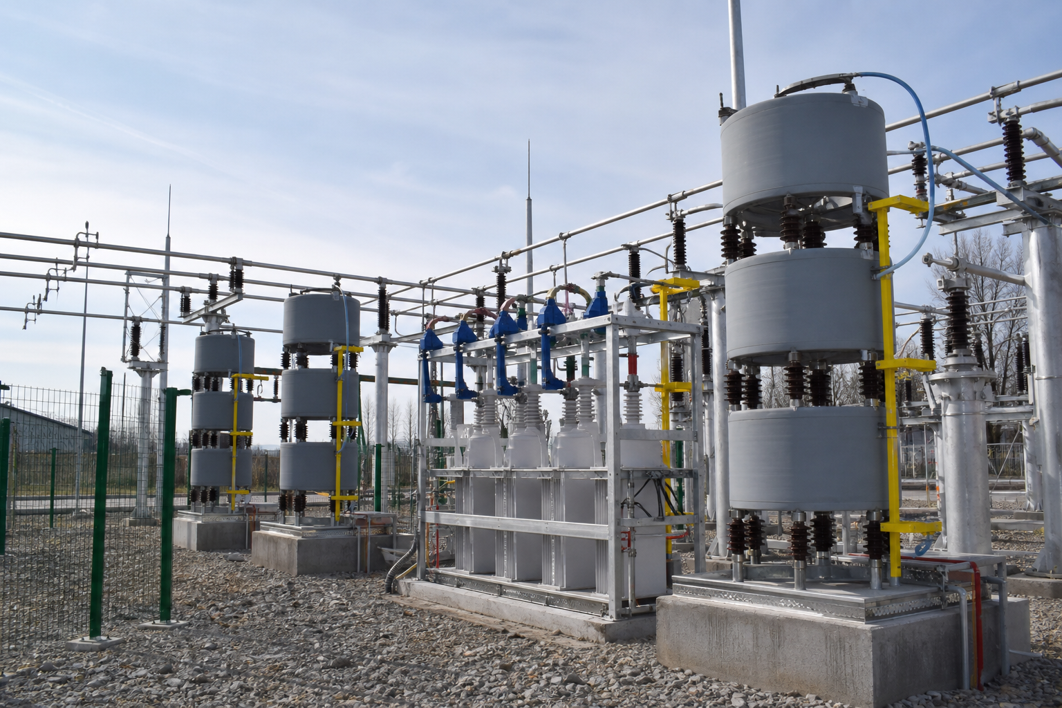
PoW on each individual close still helps, but it does not replace interlocking, minimum time between operations, or reactor strategy when two banks share a bus. Rapid return-to-service after a brief outage—when several stages try to come back together—is another classic trap for back-to-back switching.
Published transmission studies illustrate how large the difference between uncontrolled and PoW closing can be under defined conditions. Those figures belong to those networks and methods; they are evidence that timing works, not a nameplate guarantee for every plant.
A Dutch 150 kV simulation study reported that without PoW, studied capacitor-bank and cable energizations exceeded a 10% rapid-voltage-change policy threshold, while PoW kept the investigated 25–75 MVAr bank cases under a 5% RVC grid-code limit across Monte Carlo runs.
A separate 400 kV field-and-simulation case at a utility substation reported uncontrolled peaks near 1.04 kA and 479 kV versus PoW zero-cross peaks near 539 A and 412 kV—roughly a 51% current reduction and about 15% voltage-peak reduction in that study’s framing. Treat those rapid voltage change and peak-reduction percentages as study-scoped proof of mechanism.
From the field: Your bus stiffness, bank size, breaker scatter, and residual-charge policy still decide the result you measure on site (Eskom PoW field and simulation paper).
Comparing PoW with Reactors, Pre-Insertion, and Discharge Design
PoW is one mitigation path; series reactors, pre-insertion resistors or inductors, and deliberate discharge design remain common tools, and many projects combine them.
| Approach | What it mainly controls | Typical fit | Watch-outs |
|---|---|---|---|
| Point-on-wave / controlled switching | Closing (and sometimes opening) angle vs voltage or residual state | Frequent switching where breaker repeatability supports targets | Needs timing data, sensors, and residual awareness |
| Series current-limiting / detuning reactors | Peak inrush and often harmonic interaction | Single and back-to-back banks; automatic steps | Adds loss, footprint, and reactor-ratio engineering |
| Pre-insertion resistor (PIR) or pre-insertion inductor | Temporary impedance during make | Many HV breaker applications; sometimes combined with CSD | Two-stage mechanism; coordination of PIR and main-contact timing |
| Discharge resistors / timed reclose blocks | Residual voltage before the next close | Any switched bank that may reclose quickly | Does not by itself fix a bad make angle |
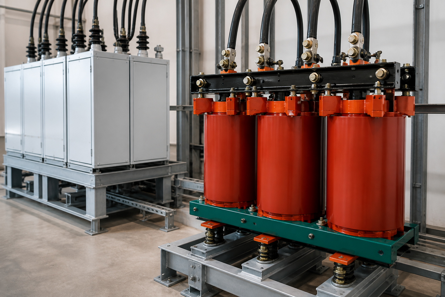
Industry survey material on shunt capacitor switching lists controlled switching, pre-insertion resistors, current-limiting inductors, and semiconductor-assisted devices among the alternatives utilities evaluate. When a project already pairs pre-insertion impedance with controlled closing, both make intervals still have to be coordinated—so “PoW or PIR” is often the wrong binary.
Important: Point-on-wave switching limits energization stress. It does not move parallel resonance away from characteristic harmonics the way a properly detuned reactor bank or filter study does. On VFD-heavy or furnace-fed buses, humming reactors, overheated cans, and blown fuses can still appear after “perfect” zero-cross closes if the harmonic design is wrong (Capacitor bank inrush guide).
Specifying Breaker Timing and Bank Options Buyers Evaluate
Buyers should match breaker repeatability and dielectric closing behavior to the PoW targets, then align bank configuration, capacitive switching duty, and residual-voltage policy with how often the stages will move.
Controlled-switching application notes commonly look for closing scatter on the order of ±0.5 ms to ±1.0 ms when zero-cross targets matter, and for a rate of decrease of dielectric strength (RDDS) high enough to reach the intended making point without a long pre-arc into a high-voltage region of the wave. Independent-pole operation is the usual assumption for optimizing each phase.
Gang-operated breakers need staggered mechanisms, pre-insertion devices, or a different mitigation story. Opening brings a second checklist.
Capacitive current zeros occur near voltage peaks, so recovery voltage across the parting contacts is demanding. Restrike risk and capacitive interrupting ratings are why engineers ask about capacitor switching duty instead of treating any feeder breaker as interchangeable.
Surveyed utilities often switch shunt banks frequently—sometimes on the order of daily operations—so endurance and restrike performance are not academic. Bank-side options sit beside the breaker: series reactor ratio, discharge design, fixed versus automatic groups, and interlocking between parallel banks.
If the project only needs rare fixed compensation, elaborate PoW hardware may buy little. If the controller will step several times per hour, timing quality and inrush limiting become part of the same purchase decision.
When a High-Voltage Power Factor Compensation Package Fits
A medium- or high-voltage shunt compensation package fits when you are buying the bank, reactors, discharge path, and switching mode as one engineered assembly—and you want to evaluate PoW or controlled-switching options without pretending the cabinet itself is a branded PoW relay.
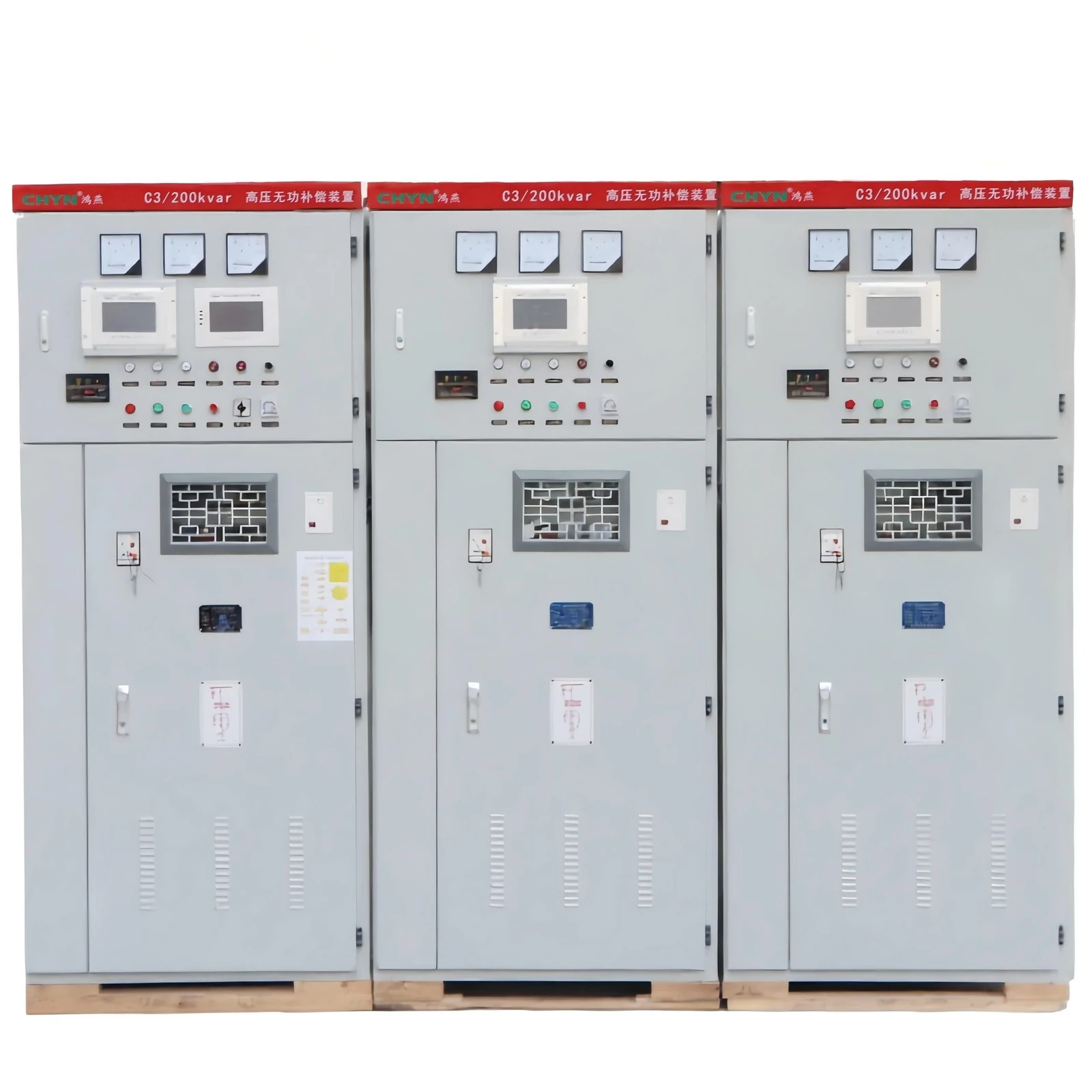
CHYN’s High Voltage Power Factor Compensation Series groups medium- and high-voltage capacitor banks, TSC, SVG, and voltage-regulation systems for project-specific reactive power and power-factor work. Within that line, the HYTBB Medium and High Voltage Reactive Power Compensation Cabinet is a shunt capacitor bank for power-frequency systems in the 1–35 kV class.
The product documentation describes series reactors for inrush and harmonic limiting, discharge circuits that bring residual voltage down after disconnection, and fixed, manual, or automatic group switching. Those are the mitigation levers buyers actually compare when a controlled-switching device may sit on the breaker rather than inside a CHYN-labeled “PoW module.”
Choose this path when voltage level, capacity, and harmonic conditions call for a packaged HV bank rather than a low-voltage compound-switch cabinet. Prefer a different route when the only missing piece is a standalone controlled-switching relay that your switchgear OEM must supply, or when the bus problem is primarily harmonic resonance rather than closing angle.
Related reading on CHYN’s site covers broader HV power-factor configuration and project filter work; this page stays on switching timing and bank-side mitigation choices.
FAQ
What is point on wave switching for capacitor banks?
It is controlled closing—and sometimes controlled opening—synchronized to a target angle on the AC voltage wave so the voltage difference across the switch at contact make stays small, which limits capacitor bank inrush current when the step connects.
Why does switching a capacitor bank cause inrush current?
Capacitors need charging current whenever terminal voltage changes quickly. Closing at a high instantaneous ΔV forces a large transient until the capacitor voltage catches the bus.
Is zero-voltage switching the same as point-on-wave control?
Zero-voltage switching is the discharged-bank case of PoW—closing near zero volts. PoW also covers closes at peak or intermediate angles when residual charge remains after a previous open.
What is back-to-back capacitor bank switching?
It is energizing a second bank or step while another is already connected on the same bus. The combined network can produce much higher transient current than either step alone.
Does switching off discharge the capacitors immediately?
No. After current interruption, capacitors typically retain near-peak voltage until discharge devices or time decay reduce it. The next close must account for that trapped charge.
Do I still need reactors or detuning if I use point-on-wave switching?
Often yes on distorted industrial buses. PoW reduces energization transients; it does not replace reactor ratio selection or a harmonic study when resonance is the failure mode.
What breaker traits matter for controlled closing?
Repeatable operating time, adequate RDDS for the intended target, independent-pole control when each phase must hit its own angle, and capacitive switching / restrike performance matched to bank current and back-to-back duty.
How should readers treat published RVC or peak-reduction percentages?
As study-scoped evidence that timing can work under defined network and breaker conditions—not as a guaranteed reduction for every site voltage, bank size, or residual-charge policy.