
 Zhejiang Hongyan Electric Co., Ltd.





































An active harmonic filter senses the load current, computes the harmonic part, and injects an opposing current at the point of connection. Plant engineers who look up how active harmonic filter works need that cycle before they open a catalog. That same cycle is what an active power filter is.
People who ask what is active power filter want that cycle.
On a low-voltage bus the nonlinear loads are usually drives, rectifiers, and other electronic supplies. Their current is lumpy. The cabinet does not replace those loads.
It adds a second current so the upstream conductors carry a waveform closer to a sine.
Sensing comes first, then the split between fundamental and harmonic current, then the inverter, then what a load step does, then where reactive current sits, then the published HYAPF fit.
What the Load Current Does in One Pass
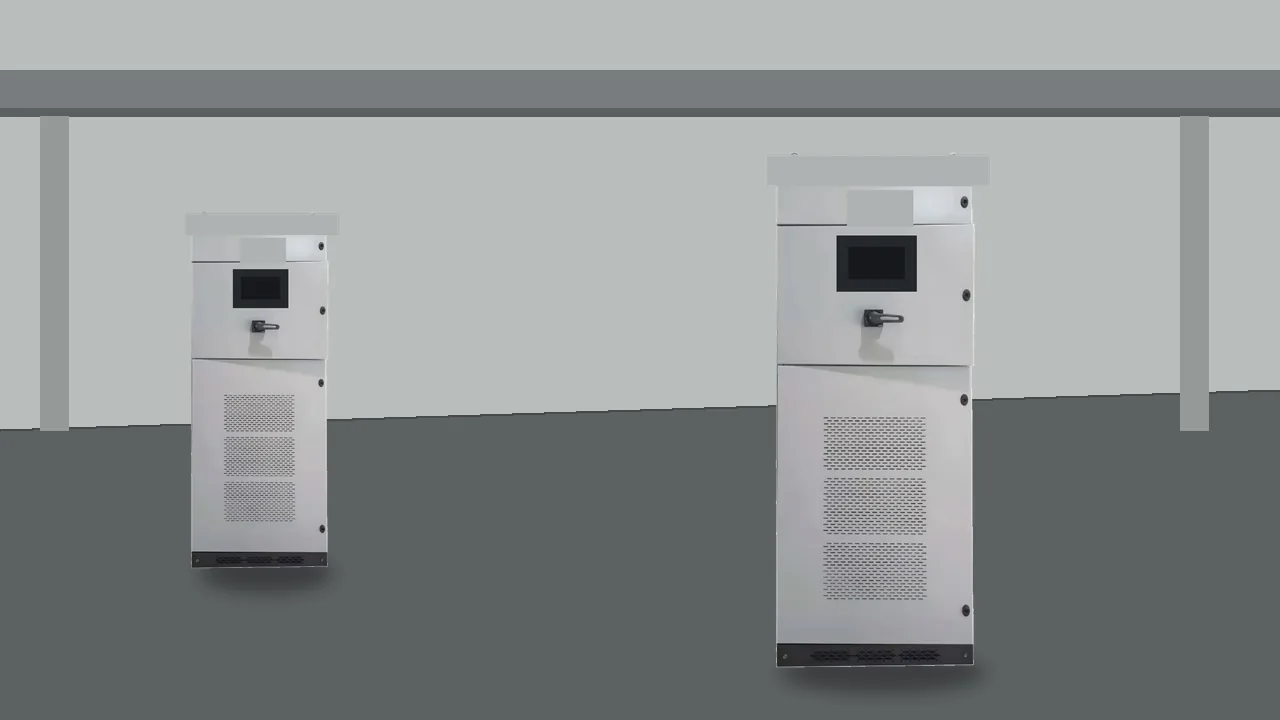
The cabinet senses load current, computes the harmonic part, and injects the opposing current. That sense-compute-inject cycle is the whole job in one pass.
Picture a motor control center with several drives running. The drives draw current in pulses. A current transformer on the load conductors reports that waveform to the controller.
The report is the input. The output is a current the cabinet pushes back onto the same bus.
Upstream of the meeting point, the supply current is the load current plus the cabinet current. When the cabinet current is the opposite of the harmonic part, those harmonic pieces shrink in the supply current. The drives still draw whatever current their rectifiers demand.
The cancellation is local to the point of connection.
A shunt active power filter does this in parallel. It is not placed in series with the feeder like a line reactor, and it does not sit as a tuned branch of capacitors and reactors. The parallel path is what lets the cabinet add current without carrying the full load current through its own switches.
| Step | Current in view | What the cabinet does |
|---|---|---|
| Sense | Load current from the current transformer | Reports the waveform the loads are drawing |
| Compute | Harmonic current | Sets the fundamental aside and keeps the harmonic component |
| Inject | Compensating current | Adds the opposing current at the point of connection |
The table is the same cycle a plant engineer can trace with a power-quality meter. One channel on the load conductors, one channel on the cabinet output, one channel upstream. The upstream channel is the one that should look closer to a sine after the cabinet runs.
How the Harmonic Part Is Pulled Out of That Current
Extraction separates the harmonic component from the fundamental before any current is built. The controller needs that split because the cabinet should cancel the distortion, not the useful part of the load current that does real work.
Literature on the shunt active power filter splits the controller into a few jobs that sit in this order. Harmonic current extraction comes first. Synchronization keeps the result lined up with the bus voltage.
A DC-link regulator holds the energy store that the inverter will draw from. Current generation turns the computed waveform into switch commands.
Those jobs are the active power filter working principle in hardware language. Extraction can be done in the time domain or by separating frequencies. The plant engineer does not have to pick an algorithm from a paper.
The engineer does have to know that a wrong input current makes every later job wrong.
From the field: A forum user described an active power filter as a small mains inverter that measures line current, or the current on the branch feeding the supplies, and then cancels the lumpy harmonic part — source: EEVblog.
That remark is the load-current sensing problem in plain words. If the sensor sees only an already corrected current, the controller computes a small harmonic part and injects too little. If the sensor sees the cabinet output as though it were the load, the controller can chase its own current.
The sensed current has to be the distorted load the cabinet was asked to clean. The cabinet display shows current, power, and distortion while that current is on the bus.
People sometimes hear "reverse current" and stop there. The reverse relationship is specifically the harmonic component, phase-opposed to the load's harmonic current. The fundamental current that feeds the motors stays with the supply.
Cancelling the fundamental would fight the current that feeds the motors.
How the Opposing Current Reaches the Point of Connection
A parallel inverter adds the opposing current where it meets the load current. The power stage is a voltage source inverter. It uses a DC store and switches that form the computed waveform.
The inverter does not pour an arbitrary sine into the bus. It builds the compensating current: the piece that was extracted, flipped in sign. That current is what meets the load at the point of connection.
The current that leaves the inverter is what the upstream meter can see.
Engineers also call that meeting place the point of common coupling when they are talking about the utility boundary. On a plant bus the same idea is local. The cabinet can tie at a distribution panel, at a transformer secondary, or beside a group of drives.
The electrical fact does not change. Load current and cabinet current share the node, and the supply current is their sum.
A useful mental picture is two hoses into one header. The loads pull a lumpy flow. The cabinet pushes an opposing lump.
The pipe back to the transformer carries the remainder. If the opposing lump is late, or pointed at the wrong phase, the remainder gets worse, not better.
That is why synchronization sits beside extraction. The computed harmonic current has to land on the correct phase angle of the bus. If the sensed current is the wrong waveform, the later jobs follow that mistake.
The cabinet then injects a current that adds to the harmonic part instead of opposing it.
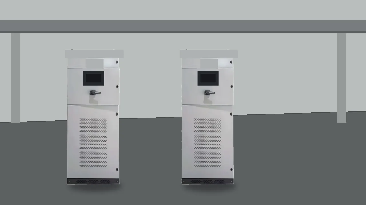
Several cabinets on one bus still share that node. Modular units can run in parallel when the harmonic current is larger than one frame. They do not change the cycle.
They only share the compensating current the extraction step asked for.
What a Load Step Does to the Injected Current
The injected current has to be computed again when the load current changes. A drive that starts, a second rectifier that closes, or a line that drops to light load all change the harmonic component. The cabinet repeats the sense-compute-inject cycle on the new waveform.
A tuned passive trap does not do that. It is built for a chosen frequency and a chosen load band. When the plant runs at a very different current, that branch can sit off the harmonic it was meant to catch, or it can interact with the source impedance.
The active cabinet's advantage is the repeated measurement. The sheet still leaves each order inside the ampere rating of the frame.
Watch the meter through a start. Load current jumps. For a short interval the upstream current still carries the new lumps, because the controller is working from the samples it has.
Then the injected current takes the new shape. If the upstream waveform never settles, the sensor is on the wrong conductors, the cabinet is already at its current limit, or the bus impedance is outside what the installation was built for.
The limit matters. The inverter can only push the current its switches and its DC store can support. Extra harmonic current beyond that rating stays in the supply.
Adding a second modular frame is a capacity decision. It is still the same cycle, with the compensating current split across frames.
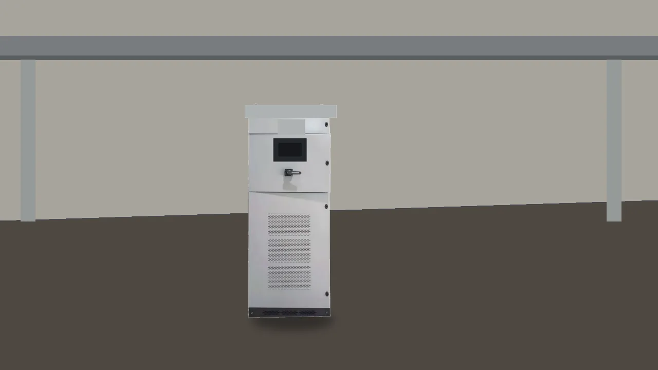
Operators sometimes expect the display to freeze on a single distortion number. The useful display is the one that moves with the load. Voltage, current, distortion, and power factor on the cabinet screen are there so the cycle can be watched, not so a single snapshot can stand in for a week of production.
Where Reactive Current Sits Beside the Harmonic Job
The sheet allows reactive-power support and does not publish a separate var rating. Harmonic current and reactive current are different pieces of the same load current. Extraction can identify both.
Ask the inverter to inject either, within the current it has left.
Displacement current is the part that sits out of phase with voltage at the fundamental frequency. Harmonic current sits at other frequencies. A plant can have a poor power factor from induction motors and a distorted current from drives at the same time.
One cabinet may be set to address both. That setting still consumes ampere capacity. Amperes spent on vars are amperes not spent on harmonic current.
The published HYAPF description says the filter can support reactive-power or load-imbalance compensation around nonlinear loads. Read that as a listed function, not as a sized var study. The page does not give a separate reactive-current ampere figure, and it does not show a one-line that would tell you to skip a dedicated var device.
Load imbalance is the third piece. Uneven phase currents are not the same as harmonic current. The controller can be arranged to circulate current that evens the phases, again inside the same ampere budget.
If the bus problem is only imbalance, say so in the enquiry. If the bus problem is only harmonics, do not spend the whole rating on vars by habit.
A passive capacitor bank corrects fundamental reactive current in steps and can resonate with harmonic current. That is a different device with a different failure. Mentioning it here only keeps the cycle clear.
The active cabinet's reactive support, when enabled, is still an injected current, recomputed with the load. A switched capacitor bank moves in discrete steps.
Which HYAPF Product Fit Carries This Injection
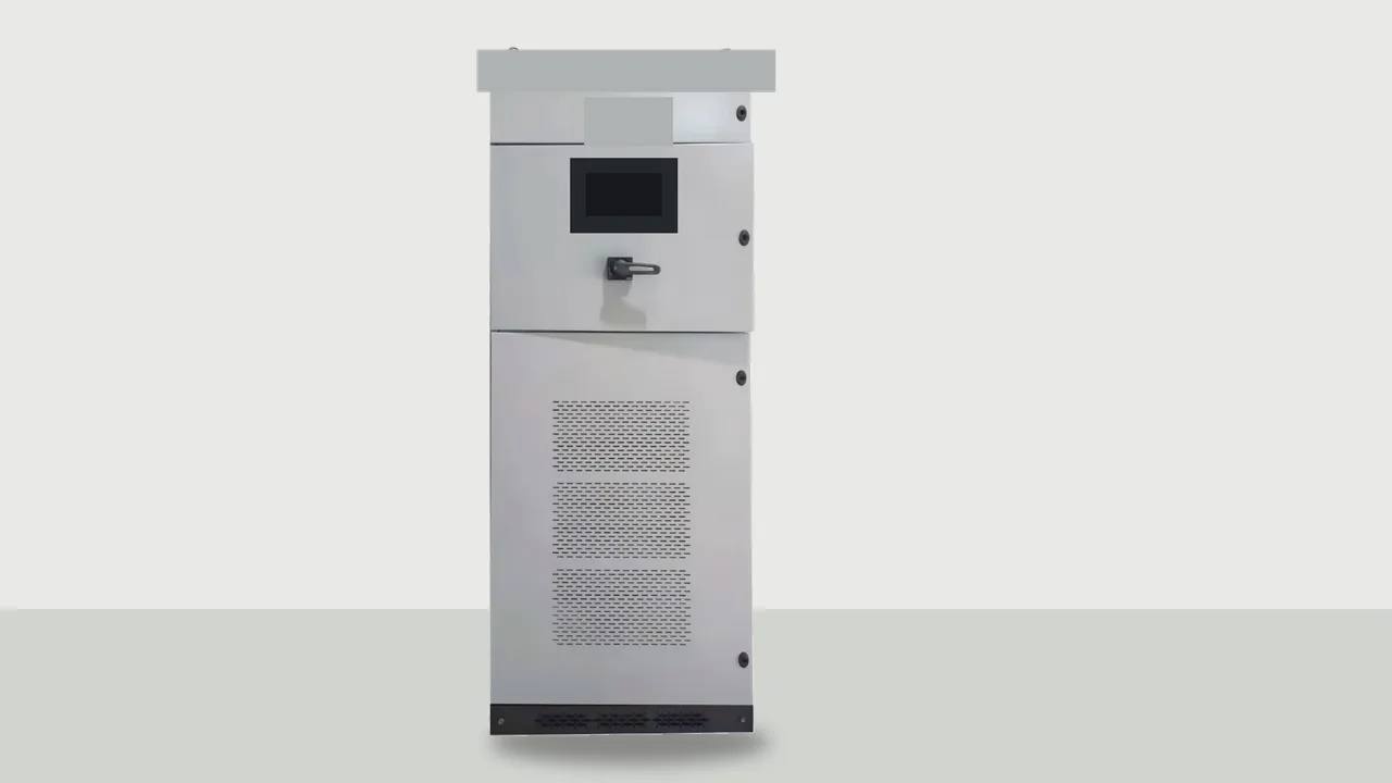
For this injection, the published low-voltage cabinet is HYAPF. The HYAPF Series Active Power Filter measures load current in real time and injects an equal, opposite harmonic current into low-voltage distribution networks. It sits in the Active Power Filter Series.
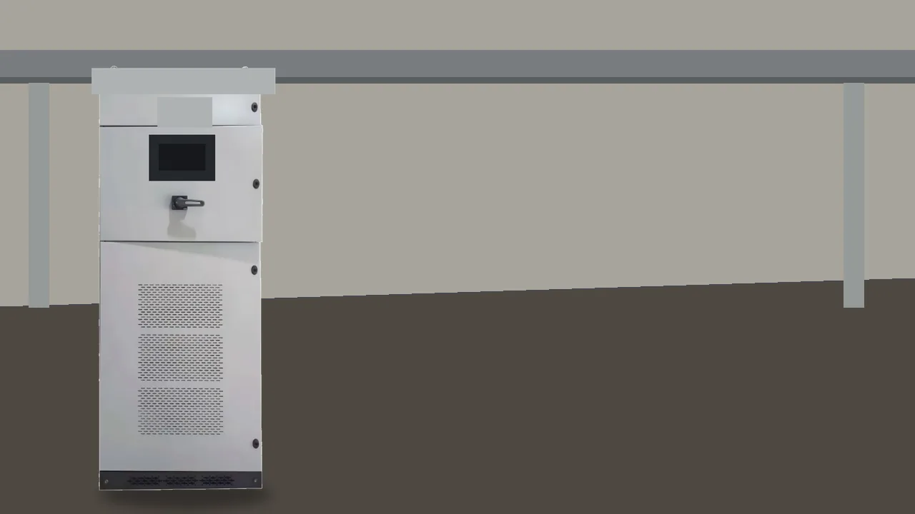
The architecture is modular, so filtering current can be built from frames instead of from a single fixed block. The page also says the cabinet can mitigate multiple harmonic orders, improve the current waveform, and support reactive-power or load-imbalance compensation. Those are the functions that belong on the cycle above.
They still leave the site measurement to the engineer on that bus.
The published cabinet lists these figures.
| Sheet item | Published value |
|---|---|
| Rated voltage | 400 V / 690 V optional |
| Harmonic compensation range | 2nd-51st order |
| Compensation span in the feature list | up to 51 orders |
| Response time | under 10 ms |
| Control accuracy | THD under 5% |
| Switching frequency | up to 20-30 kHz |
| Feature-list switching note | up to 20 kHz |
| Detection accuracy | up to 0.1% |
| Sampling accuracy | up to 1.25 us |
| ADC | dual-channel 12-bit, 10 V input range |
| Topology note | loss reduced by 60% |
| Parallel operation | modular parallel operation, hot-swappable |
Read the response row as the speed of the cycle, not as a promise about every bus. Read the order span as the range the controller can address, not as proof that a particular drive's spectrum fits in one frame. The ampere rating still has to cover the harmonic current you measured, including any share assigned to reactive current or imbalance.
The control hardware on the page is a fast digital platform with a stated detection accuracy and a fast sampler. That hardware is what makes the compute step short enough to follow a load step. The page also lists a touch display of voltage, current, distortion, and power factor, which is the window an operator uses to see the cycle while the bus is live.
Keep a frame available with parallel frames and hot-swap. Those features do not change the current path.
If a frame is out, the remaining frames can only inject the current they still have.
Use the product page when the bus is low voltage and the job is this injection. Bring a recent current waveform, the voltage, and a note on whether reactive current or imbalance must share the rating. The installer's one-line still has to show where the cabinet ties in.
Frequently Asked Questions
These questions stay on sensing, on the ampere limit, and on the split between harmonic current and reactive current.
Why can sensing transformers run hot beside an active filter?
A field report described breaker current transformers heating after an active harmonic filter was added on the feeder. Replies pointed at frequency and at heating in the secondary and in the iron. The filter's own sensing has to match the current and the frequencies it is asked to see.
A metering transformer chosen only for fundamental current can be the wrong part for that job.
What fails if the measured current already includes the injected current?
The controller then treats a cleaned, or partly cleaned, waveform as the load. Extraction understates the harmonic current, and the injected current is too small. The opposite mistake, reading the cabinet output as the load, makes the controller chase itself.
The sensed current has to be the distorted load the cabinet was installed to cancel.
Can one cabinet cancel every order a drive produces?
The published range runs from the 2nd order through the 51st order. That is a span, not a guarantee that every ampere of a drive's spectrum fits in one frame. Orders inside the span still consume rating.
Orders beyond the span are outside what the sheet claims.
What happens when the required opposing current exceeds the cabinet rating?
The inverter stops at the current it can build. The rest of the harmonic current stays in the supply. A second modular frame can share the compensating current.
It cannot invent ampere capacity the frames do not have.
Why does a tuned passive trap stay fixed while drives start and stop?
A passive branch is tuned for a chosen frequency and a chosen load band. It does not measure the new load current and recompute an injected waveform. When drives start and stop, the harmonic current moves, and a fixed branch stays on its original tune.
Does cancelling harmonic current replace a dedicated var source?
Cancelling harmonic current removes the distortion piece. Reactive current at the fundamental is a different piece. The HYAPF page says the cabinet can support reactive-power compensation, and it does not publish a separate var rating.
A bus whose main problem is vars still needs that rating worked out, rather than assumed from the harmonic span.