
 Zhejiang Hongyan Electric Co., Ltd.
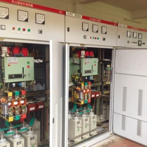
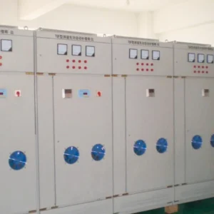
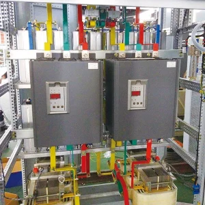
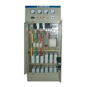
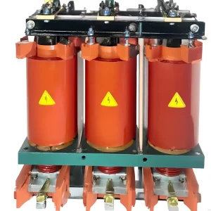
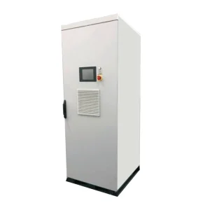
Capacitor bank contactor selection must cover capacitor-switching duty, continuous branch current and the actual switching sequence. A motor-duty current rating alone is not sufficient evidence. For a low-voltage bank, ask for the capacitor-switching rating at the project voltage, the permitted inrush conditions, any required damping arrangement and the allowed switching frequency. Confirm these against the complete branch design before accepting a replacement or a new panel.
This article focuses on selecting and documenting an electromechanical switching device inside a capacitor-bank design. It does not provide a live wiring procedure or establish that every compensation cabinet contains the same contactor arrangement.
Start with the load duty, not the contactor frame size
A capacitor branch creates different switching conditions from a motor. The contactor must withstand the intended closing duty as well as carry the energized branch current. A physically larger contactor or a familiar ampere label does not automatically establish suitability for that combination.
AC-6b is the utilization category associated with capacitor-bank switching in IEC contactor selection practice. Ask the device supplier to identify its declared capacitor-duty rating and the associated application conditions. The IEC 60947-4-1 publication page identifies the low-voltage electromechanical contactor standard and its scope. A public summary is not the complete standard and does not substitute for a configuration-specific selection.
Put the operating voltage, frequency, branch arrangement and expected operations into the enquiry before requesting a model number. This avoids comparing one quotation based on a single isolated capacitor with another based on switching into an already energized multistep bank.
Separate continuous current from closing inrush
The fundamental current of an ideal balanced three-phase capacitor bank can be estimated from its reactive output. With Q in kvar and line-to-line voltage U in volts, I = 1000Q / (√3 × U), giving line current in amperes. The expression describes a balanced sinusoidal operating point; it is not an inrush-current calculation or a final contactor rating.
For illustration, a 50 kvar branch delivering that output at 400 V has a calculated fundamental line current of about 72.2 A. This is an arithmetic example, not a CHYN product specification. Actual selection must consider the approved capacitor and reactor combination, voltage conditions, harmonic duty and the device manufacturer’s rating rules.
Closing inrush is a different event. Its magnitude depends on the electrical circuit and switching conditions, including whether other capacitor stages are already energized. Do not derive the permissible peak by multiplying the calculated 72.2 A by a convenient universal factor.
Record the information that controls selection
| Selection input | What to request | Why it changes the decision |
|---|---|---|
| Capacitor-switching rating | Declared duty at the actual operating voltage | A motor-duty label describes another application |
| Bank configuration | Single-step or multistep arrangement and branch schedule | Already energized stages affect closing conditions |
| Inrush control | Approved damping device and application restrictions | The contactor and limiting arrangement must work together |
| Operating frequency | Expected switching events and allowed device duty | Repeated operation affects electrical and mechanical life |
| Thermal environment | Enclosure temperature and mounting arrangement | Installed conditions may differ from catalogue conditions |
| Protection coordination | Specified protective devices and documented coordination | A contactor is not a substitute for fault protection |
This qualitative checklist organizes the project inputs; it gives no universal current multiplier, switching interval or fault rating. Use the applicable standard, current device documentation and the approved bank design to resolve each row.
Understand what pre-insertion resistors actually do
Some capacitor-switching contactors use an early-make auxiliary path with damping resistors. In that arrangement, the resistor path acts before the main contacts complete the normal current path. Its purpose is to reduce the severity of the closing transient within the manufacturer’s stated application limits.
That description does not mean every capacitor-duty contactor uses the same sequence, resistor value or construction. Specify the complete approved device rather than assembling an improvised resistor circuit around a standard contactor. Timing, thermal duty and the relationship between the auxiliary and main contacts are design matters.
Also distinguish closing-current limitation from capacitor discharge. A pre-insertion assembly does not automatically establish that a disconnected capacitor is safe to touch or ready for immediate reconnection. The discharge arrangement and controller’s reconnection restrictions require separate verification.
Check the most demanding stage combination
A multistep bank should be reviewed as a system. Identify which stages can be energized together, which stage may close next and what other components remain connected. Selection based only on the first stage’s isolated closing condition can miss a more demanding combination later in the sequence.
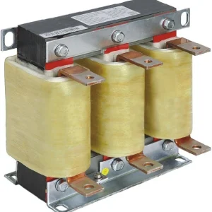
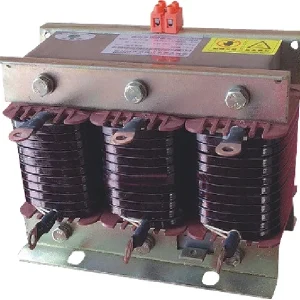
If series reactors are included, provide their approved ratings and relationship to the capacitors. Do not assume that adding a reactor allows any contactor to be used, or that a contactor’s selection table for an undetuned bank applies unchanged to every detuned branch.
The guide to back-to-back capacitor-bank switching addresses the system-level transient question. Use it alongside the device selection review. It complements this article by examining the network event rather than the procurement evidence for one contactor.
Match control commands to permitted switching duty
Collect the expected load profile and controller operation log. A bank that changes stages occasionally is a different duty from one that repeatedly switches around a rapidly varying demand. Ask for a declared operating frequency and service-life basis for the actual capacitor duty, rather than relying on an unrelated mechanical-life number.
Confirm the coil supply and its permitted variation. Include the control transformer, interposing relays and source conditions during large load changes. A device cannot be evaluated properly if its control voltage is unknown or if the proposal silently assumes a different supply.
Where the intended duty is too rapid for a mechanical arrangement, review the overall switching technology. CHYN’s thyristor versus contactor switching comparison covers that choice. Changing technology still requires a complete branch design and does not remove harmonic, protection or thermal checks.
Treat a failed contactor as evidence to investigate
Welded contacts, discoloration or repeated switching faults should trigger a review of the installed duty. Preserve the failed component identity, controller event history and branch configuration. Check whether the installed part matches the approved bill of materials before assuming that an identical-looking replacement is acceptable.
Ask qualified personnel to investigate the relevant connections, control supply, limiting assembly, cooling conditions and capacitor branch under an approved procedure. Do not bypass a damaged limiting resistor or keep operating a failed stage to maintain a displayed power factor.
The UK HSE’s electrical-safety guidance stresses secure isolation, release of stored energy and proving exposed conductors dead before work. Capacitor-bank maintenance must follow the applicable local rules and manufacturer instructions. A controller stop command or an open contactor is not a complete maintenance-isolation procedure.
Ask for an assembly-specific proposal
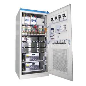
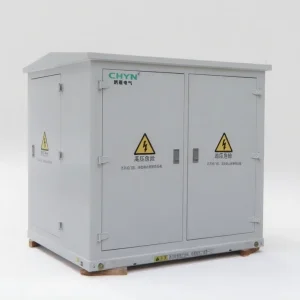
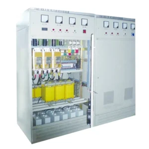
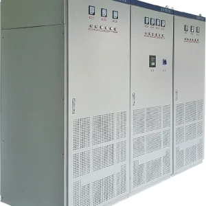
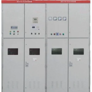
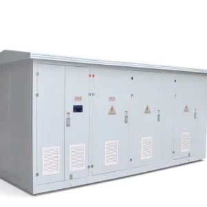
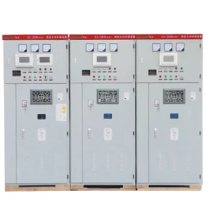
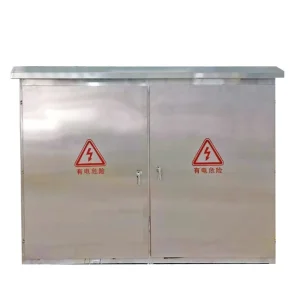
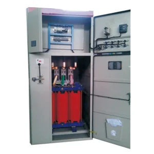
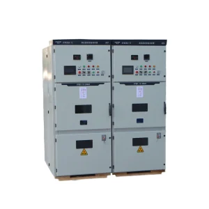
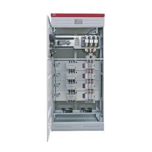
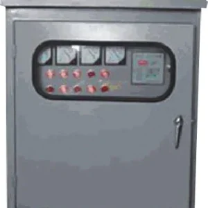
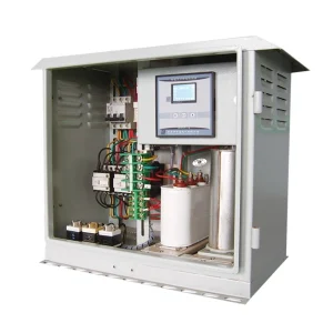
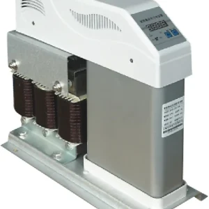
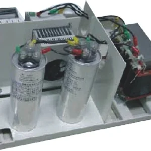
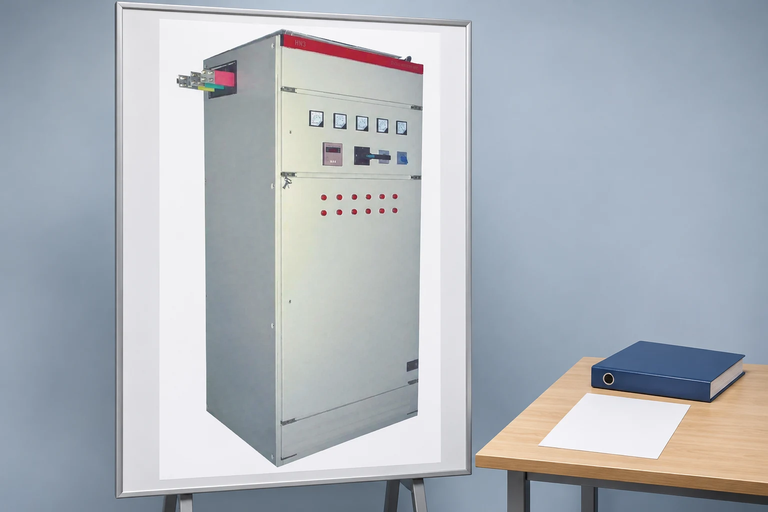
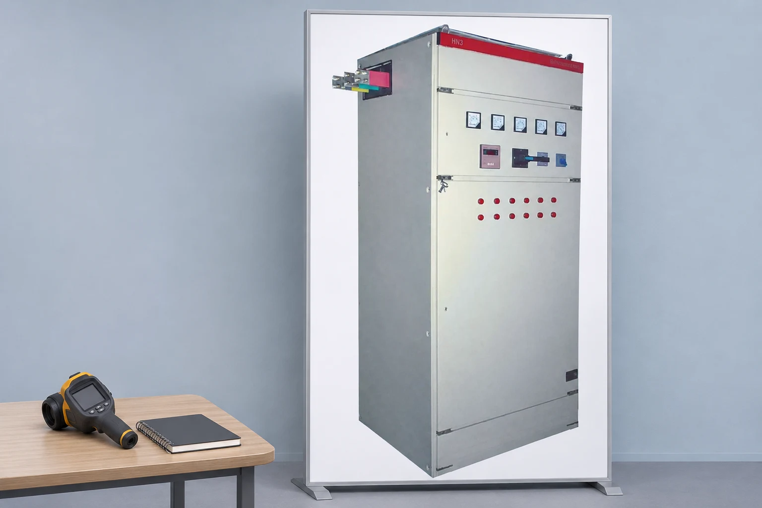
The CHYN HYTBBJ low-voltage compensation system provides a relevant assembly enquiry route. The closed-cabinet photograph does not reveal the internal contactor type. Ask CHYN to identify the switching hardware, capacitor/reactor branch schedule and protection arrangement proposed for your project.
A useful quotation names the contactor duty, operating voltage, stage output, expected switching frequency and required environmental conditions. It should identify whether damping components are integral, separately supplied or unnecessary under the approved selection. Request the reasoning and limitations behind any substitute device.
For replacement work, provide the existing device markings, approved drawings, capacitor ratings and known fault history. If information is missing, record the gap rather than ordering only by frame dimensions. Mechanical fit and coil voltage are necessary checks, but they are not the complete equivalence assessment.
Verify the selected duty at handover
Before energization, reconcile the delivered bill of materials with the approved selection and inspect it through the agreed procedure. Under a planned commissioning sequence, verify stage operation, alarm behavior and the relevant electrical observations. Retain the settings and test conditions so later maintenance can identify changes.
After operation begins, compare the actual switching log with the assumed duty. A process modification can make an originally reasonable device selection unsuitable without changing the total installed kvar. Keep the permitted operating envelope with the panel records and review it when the load pattern or stage arrangement changes.
For the overall assembly context, see what a capacitor bank is used for. Define the bank’s compensation objective before selecting individual switching devices, so the component schedule reflects the intended operating duty.
Further learning: capacitor switching principles
The NPTEL IIT Guwahati lecture explains thyristor-switched capacitors as an alternative switching principle. It supports the discussion of switching technology and does not provide a mechanical contactor selection table or instructions for modifying a cabinet.
Watch Lec 19: Thyristor Switch Capacitor (TSC) on YouTube.
Frequently asked questions
Can a motor-duty ampere rating determine capacitor suitability?
No. Capacitor switching imposes a different duty. Request the declared capacitor-switching rating at the project voltage, permissible inrush conditions and operating frequency. Also confirm the installed thermal environment and coordinated branch protection. A similar frame size or a larger motor-duty current label does not establish equivalence.
Do all capacitor contactors need pre-insertion resistors?
Not necessarily. The appropriate arrangement depends on the device rating and the calculated application conditions. Some approved devices use an integral early-make resistor path; other selections have different restrictions. Use the complete manufacturer-approved arrangement rather than adding or removing resistors based only on a generic description.
Does a pre-insertion resistor discharge the capacitor safely?
Do not assume that it does. Closing-current limitation and safe discharge are separate functions. Verify the capacitor discharge arrangement, reconnection restrictions and maintenance procedure for the actual bank. Before work, qualified personnel must follow the applicable secure-isolation and stored-energy instructions and verify the equipment is safe.
What is needed to approve a replacement contactor?
Provide the original approved selection, device markings, coil supply, branch capacitor and reactor data, switching history and known failure details. Ask for documented equivalence under the actual capacitor duty. Physical fit alone is insufficient, and unexplained failures should be investigated before returning the stage to normal service.