
 Zhejiang Hongyan Electric Co., Ltd.
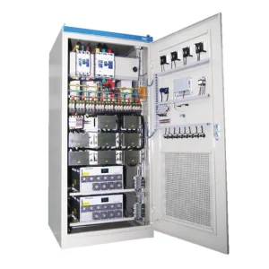
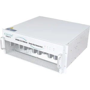
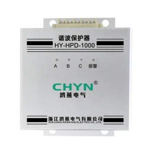
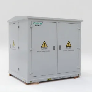
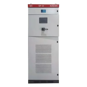
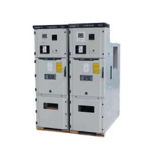
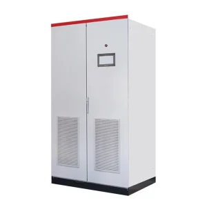
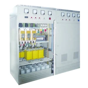
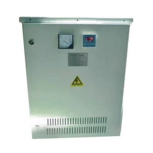
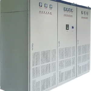
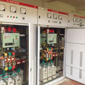
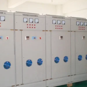
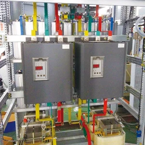
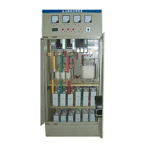
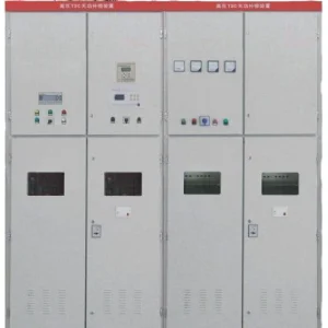
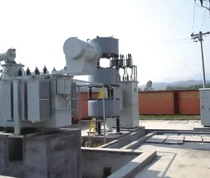
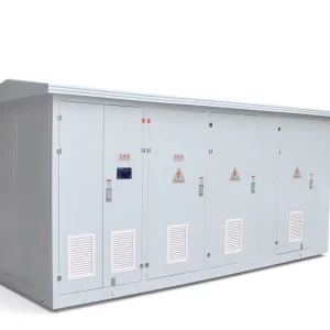
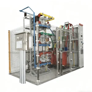
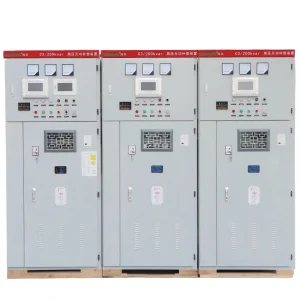
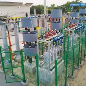
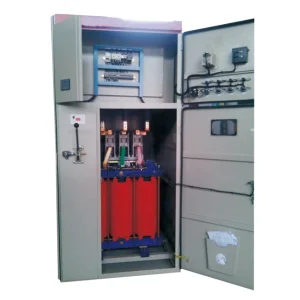
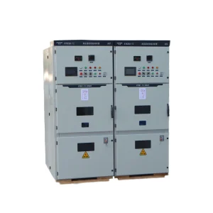
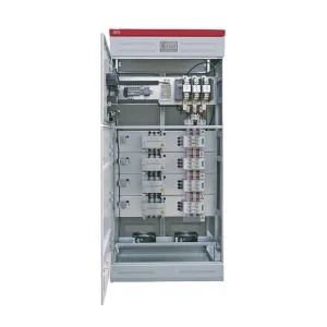
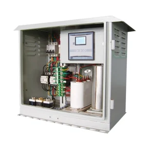
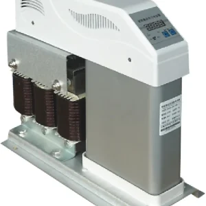
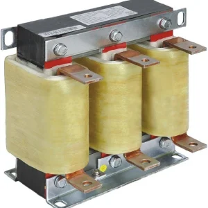
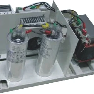
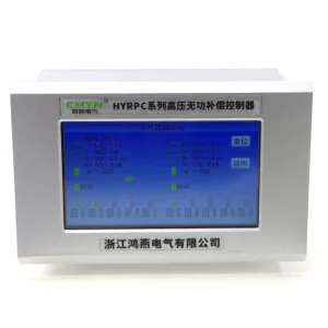
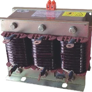
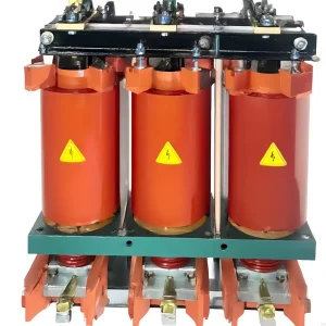
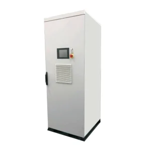
An active harmonic filter on a generator supply needs a separate operating review from the same filter on utility power. Confirm the source impedance, connected nonlinear loads, current-transformer measurement boundary and controller behavior in each supply mode. Then test current distortion, voltage distortion and stable load operation together. A good utility-mode result does not establish generator compatibility, and the filter’s rated compensation current alone cannot answer that question.
This guide is for engineers preparing a standby-generation upgrade or procurement package. It explains what evidence to collect, which operating states to include and how to define a meaningful acceptance test without assuming that every active filter works with every alternator.
Why changing the source changes the assessment
A drive or rectifier draws a nonsinusoidal current. The voltage distortion associated with that current depends on the network through which it flows. EPRI’s report on nonlinear loads and motor-generator sets explains why backup operation can produce different voltage-quality results from utility operation. A generator’s electrical characteristics therefore belong in the harmonic assessment, alongside the load spectrum.
Do not replace that assessment with a statement that generators are always unsuitable, or that a filter automatically solves the problem. The relevant question is whether the proposed combination of source, controls, loads and compensation operates acceptably over the required envelope. Record which alternator and regulator are actually supplied, rather than relying only on the generating set’s headline kVA.
The ARENA harmonic-study summary also identifies the interaction between harmonic currents and network impedance. Its large renewable-generator context differs from a standby set; the useful shared principle is that harmonic behavior is a system interaction, not an isolated equipment label.
Draw the utility and generator measurement boundaries
Prepare a single-line diagram for each credible switch state. Mark the transfer equipment, generator connection, filter connection, capacitor branches and loads that remain energized. A diagram showing only normal utility operation can hide a feeder that moves outside the measured zone after transfer.
Identify exactly what the filter’s current transformers measure in each state. Source-side and load-side arrangements are configuration dependent. Confirm the accepted arrangement and corresponding settings with the filter supplier. Do not move CTs or copy another model’s terminal scheme based on a general diagram.
For installations with multiple generators or a bus tie, create separate drawings where the current path changes. Establish who provides the source-status signal, who verifies it and what happens if that signal fails. A written interface schedule makes this responsibility reviewable before commissioning.
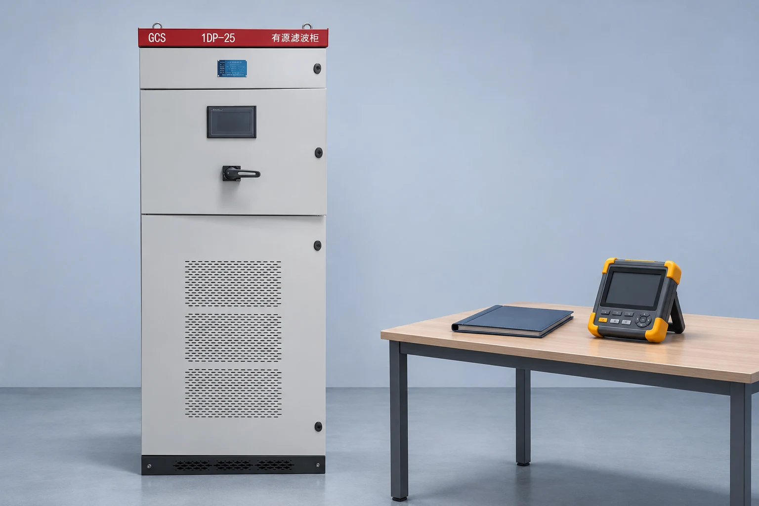
Build an operating-state test matrix
| Operating state | Evidence to capture | Question the test answers |
|---|---|---|
| Utility, representative nonlinear load | Voltage and current spectra, load list, filter settings | What is the normal comparison baseline? |
| Generator, lowest required operating load | Connected loads, compensation duty, voltage trend | Is the light-load state stable and acceptable? |
| Generator, largest required nonlinear load group | Harmonic amperes, source voltage distortion, filter utilization | Does the proposed capacity cover the intended duty? |
| Generator, approved load addition or removal | Synchronized event records and equipment alarms | Does the system recover without unacceptable behavior? |
| Return to utility | Transfer sequence, inhibit/re-enable records, process status | Does normal compensation resume as specified? |
This is a project planning matrix, not a table of universal limits. The source references above explain why impedance and load matter. The project engineer must set actual limits, test durations and allowed switching sequences for the installation. Tests involving transfer or load changes require an approved operating and safety plan.
Measure amperes and voltage, not only a percentage
Collect phase currents, fundamental current and the harmonic spectrum while identifying the operating loads. A percentage can move because its denominator changes. At low generator loading, a high current-THD number may accompany a modest harmonic current; at higher loading, a lower percentage may still represent a larger compensation requirement.
Use the same instrument definitions and averaging intervals for the before-and-after comparison. CHYN’s THD versus TDD measurement guide explains why these current indices should be distinguished. Also retain voltage distortion at the load bus, since sensitive equipment experiences the voltage waveform rather than a filter display’s current percentage.
Keep the generator’s load record with the waveform files. A successful test with a resistive load bank does not document the behavior of an untested rectifier or drive combination. Identify any substitute load and explain which part of the proposed duty it represents.
Coordinate harmonic and reactive-power objectives
If the filter is also expected to provide reactive-current or phase-balancing functions, list those duties separately. Ask the supplier to state how available current is allocated when functions operate together. An individual function’s maximum rating does not demonstrate that all functions can run at their maxima simultaneously.
Inventory existing capacitor banks and other compensators. Confirm whether their control sequence changes on generator power and who approves that sequence. Do not assume that retaining every utility-mode capacitor step is beneficial during every generator load condition.
Keep the distinction between technologies clear. The article on static var generators and active harmonic filters helps separate the main objectives. A harmonic filter should not be specified as backup energy storage, and a reactive-power function should not be treated as proof of harmonic mitigation.
Specify controller behavior during transfer
Agree on the intended state before, during and after transfer. The approved design may require an enable signal, temporary inhibition, different operating settings or other manufacturer-defined behavior. Request the exact sequence for the selected configuration; do not invent a delay value from a generic article.
Include abnormal states in the interface review. Examples include a missing source-status signal, loss of a required measurement, an unavailable filter module and a transfer that does not complete. For each state, define the expected alarm, compensation status and operator response. The appropriate response depends on the process and protection design.
Keep a versioned copy of the approved settings. If the controller configuration changes during testing, identify which results belong to each version. Otherwise a passing record may describe settings that were later replaced.
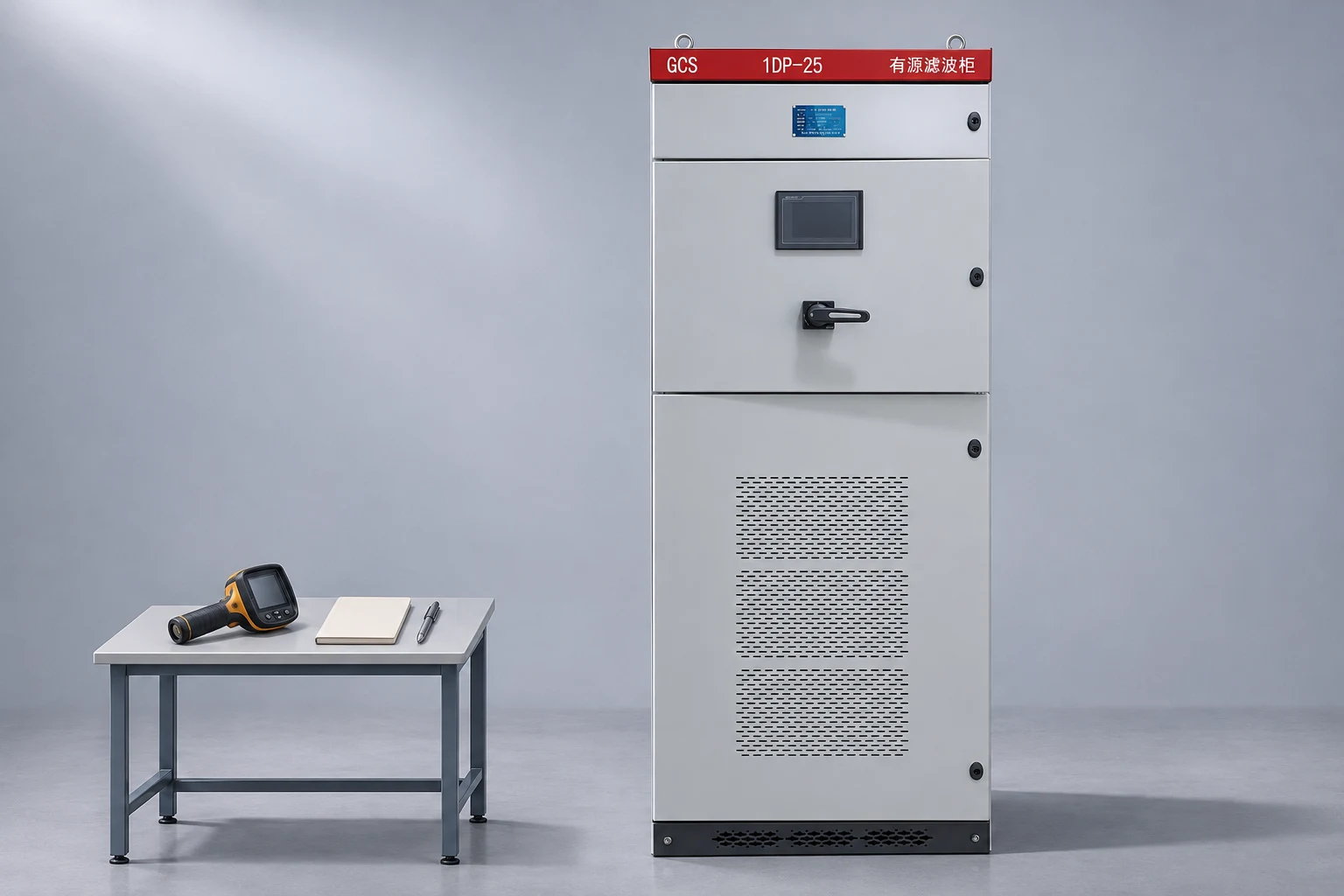
Use a staged acceptance procedure
Start with documentation checks: approved drawings, device identities, CT arrangement, protection coordination and operating instructions. Physical inspection and any electrical work must be performed by qualified personnel under the applicable isolation and stored-energy procedures. This guide does not authorize live adjustments or changes to protection.
Under the approved test plan, establish comparable baseline states and then evaluate the agreed compensation states. Record source mode, load configuration, filter status, voltage and current data, and relevant equipment alarms together. A record without the load state is difficult to interpret and should not support an unrestricted claim.
If oscillatory behavior, unexpected trips or worsening voltage quality appears, stop the affected test through the agreed procedure and preserve the recordings. Do not keep raising current limits or disabling alarms to obtain a better display number. Escalate the evidence to the generator and filter engineers for a coordinated review.
Prepare the CHYN enquiry package
The CHYN HYAPF active power filter page is a starting point for a configuration discussion. Its product description is not a generator-mode acceptance record. Request written confirmation tied to the actual generating set, network arrangement and proposed filter configuration.
Supply the single-line diagrams, source data, nonlinear load list, representative measurements and required operating modes. Add installation ambient conditions, available space, cooling constraints and the intended combination of compensation functions. State any data that remains unavailable so the supplier can identify assumptions explicitly.
Ask the proposal to name the measurement boundary, required interfaces, operating restrictions, acceptance criteria and evidence to be supplied. After commissioning, retain the tested settings and event files with the handover documents. Revisit the assessment when generators, major drives, capacitor stages or transfer arrangements change.
For the underlying compensation mechanism, read how an active harmonic filter works. That parent explanation provides the current-injection context; this generator-mode checklist adds the source-state and acceptance requirements.
Further learning: how a shunt active filter works
The NPTEL IIT Delhi lecture below explains the compensation principle. It supports the discussion of measured load current and injected compensation current; it does not validate a particular generator/filter combination or replace a site study.
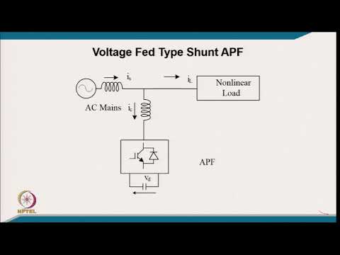
Watch Shunt Active Power Filters on YouTube.
Frequently asked questions
Does a utility-mode pass prove generator compatibility?
No. The source characteristics, connected loads and measurement boundary may differ after transfer. Obtain a configuration-specific review and test the required generator operating states. Keep voltage quality, current compensation and stable equipment operation in the acceptance criteria instead of relying only on the normal-supply result.
Can I size the filter using generator kVA alone?
No. Generator kVA does not describe the harmonic current spectrum or every simultaneous compensation duty. Supply representative measurements, source information and the operating-state matrix. Ask the supplier to identify the required compensation current and restrictions for the actual configuration rather than selecting a percentage of generator capacity.
Should the filter remain enabled throughout transfer?
The correct sequence depends on the selected equipment and approved design. Ask for written enable, inhibit and recovery behavior for the transfer arrangement, including missing signals and unsuccessful transfers. Do not copy a generic delay or assume that continuous enable is appropriate for every controller and source.
What should trigger a new generator-mode review?
A different generator, major nonlinear load changes, added capacitor stages, revised CT placement or a changed transfer arrangement can alter the original assumptions. Retain the tested configuration and repeat the relevant assessment when it changes. Historical test results apply to their documented conditions, not every later modification.