
 Zhejiang Hongyan Electric Co., Ltd.






































Choosing a static var generator vs active harmonic filter starts with separating two problems: fundamental reactive current and harmonic current. An SVG is primarily selected to supply or absorb reactive current; an active harmonic filter is primarily selected to counter selected harmonic currents. Some products provide both functions, but their available current and control priorities still have limits. The correct choice depends on measured waveforms, displacement and true power factor, load changes, and the point where performance must be achieved. A single low power-factor reading is not enough to decide which device a plant should buy.
The difference that determines the shortlist
An inductive load can draw a largely sinusoidal current that lags the fundamental supply voltage. That is a reactive compensation problem. A rectifier can draw a strongly distorted current with a comparatively small fundamental phase shift. That is a harmonic-current problem. Many industrial buses contain both types of load, so the two problems can coexist without having the same dominant cause.
An SVG uses a controlled power converter to exchange reactive current with the bus. Its principal selection question is how much inductive or capacitive compensation is needed as the load changes. An AHF measures the relevant currents and injects compensation currents so that less unwanted harmonic current flows upstream of its connection point. Its principal question is which harmonic-current duty must be handled, at what current, and under which operating conditions.
The devices can share elements of converter technology, but this does not make every SVG and AHF interchangeable. A multifunction product may allocate its current between reactive compensation, harmonic filtering, and imbalance correction. Obtain the declared capabilities of the specific model and operating mode rather than inferring them from the cabinet appearance or product family name.
SVG and AHF comparison for an industrial buyer
| Selection question | SVG emphasis | Active harmonic filter emphasis |
|---|---|---|
| What is the primary measured problem? | Changing fundamental reactive current, including leading or lagging demand. | Harmonic current from nonlinear loads that must be reduced upstream. |
| What normally drives the capacity discussion? | Required kvar range, equivalent compensation current, and load variation. | Measured harmonic amperes, selected orders, and simultaneous operating loads. |
| Which additional functions need confirmation? | Harmonic and phase-imbalance duties, if offered. | Reactive and phase-imbalance duties, if offered. |
| What must be agreed for acceptance? | Reactive-power or power-factor target at the specified measurement point. | Harmonic-current target and voltage conditions at the specified measurement point. |
| What does the name alone fail to establish? | Guaranteed harmonic filtering or ride-through capability. | Unlimited kvar output while delivering full harmonic compensation. |
This is a functional selection framework, not a claim that all products have identical boundaries. The IEEE 519 harmonic-control standard addresses steady-state power quality at the point of common coupling. A product's advertised filter performance is not, by itself, proof that an entire installation meets the applicable requirements there.
Read displacement power factor and true power factor separately
Displacement power factor describes the phase relationship between the fundamental voltage and current. True power factor is real power divided by apparent power using the relevant total RMS quantities. Harmonic current can therefore lower true power factor even when the fundamental phase relationship is already close to unity.
For approximately sinusoidal supply voltage, a useful relationship is PF ≈ DPF / √(1 + THDI2). Here PF is true power factor, DPF is displacement power factor, and current THD is expressed as a ratio rather than a percentage. The Hawaiian Electric power-quality notes explain this distinction. The simplified expression should not be extended without review to significantly distorted supply voltage or a complex unbalanced three-phase assessment.
For a hypothetical load with DPF = 0.99 and THDI = 40%, the estimate is 0.99 / √1.16 ≈ 0.919. Raising DPF to 1.00 while leaving the current distortion unchanged gives approximately 0.928. That small improvement shows why reactive compensation alone may leave true power factor disappointing. These values illustrate the equation, not an expected result for a CHYN product.
For a different load with low DPF and little current distortion, reactive compensation can be the main requirement. Follow the measured cause rather than choosing a device from the apparent severity of the PF number. For a broader explanation of the quantity itself, refer to the electrical engineering definition of power factor.
Which measurements should come before a quotation?
Record enough operating conditions to represent the actual plant: production at high and low load, large drives on and off, capacitor steps switched, and any generator or alternative supply modes. A brief measurement during a quiet shift may miss the condition that determines equipment size. Include the measurement location and the operating state with every exported result.
The data package should include three-phase voltage and current, kW, fundamental reactive power where available, true PF, DPF, current and voltage spectra, and the neutral current where relevant. Specify the meter's calculation conventions. A signed PF value can reflect a meter convention as well as the physical direction of power flow, so do not interpret the sign without checking the documentation.
Record harmonic amperes, not only THD percentages. THD can rise at light load because its fundamental-current denominator becomes smaller even when absolute harmonic current has not increased. For a compliance study, distinguish THD from the demand-based current metric required by the applicable standard. The plant engineer should identify the correct reference current and measurement point.
Capture short-term load changes when the process varies rapidly. A slowly averaged kvar value can conceal a sequence of inductive and capacitive demand. The engineering package should describe both the magnitude and the time behavior of the duty, rather than presenting a single maximum from an unlabelled spreadsheet.
Current capacity is shared when functions run together
A converter's continuous current rating is a finite resource. If it is providing reactive current and harmonic current simultaneously, neither function should be evaluated as though the other consumes no capacity. Thermal limits, harmonic order, switching behavior, and the manufacturer's control strategy can further affect the usable envelope.
As a simplified illustration, orthogonal compensation components of 60 A fundamental reactive current and 80 A aggregate harmonic RMS current have a combined RMS requirement of √(60² + 80²) = 100 A. This is an idealized current-budget example, not a complete filter-sizing method. Phase-specific duty, imbalance, neutral current, crest factor, derating, and the product's permitted operating modes still need checking.
Ask what happens when the requested current exceeds the available capacity. Does the controller prioritize harmonics, reactive power, or another function? What remains uncompensated? Does the system alarm, limit its output, or shut down? These questions turn a vague promise to “improve power quality” into a performance statement that can be tested.
When to choose SVG, AHF, or a coordinated combination
Choose SVG as the main tool when reactive demand dominates
If the evidence shows rapidly changing reactive demand, low displacement PF, or repeated leading and lagging operation, an SVG belongs on the shortlist. Confirm the required kvar range at the actual voltage, environmental derating, and sensing arrangement. Harmonic performance should be specified separately if the project needs it.
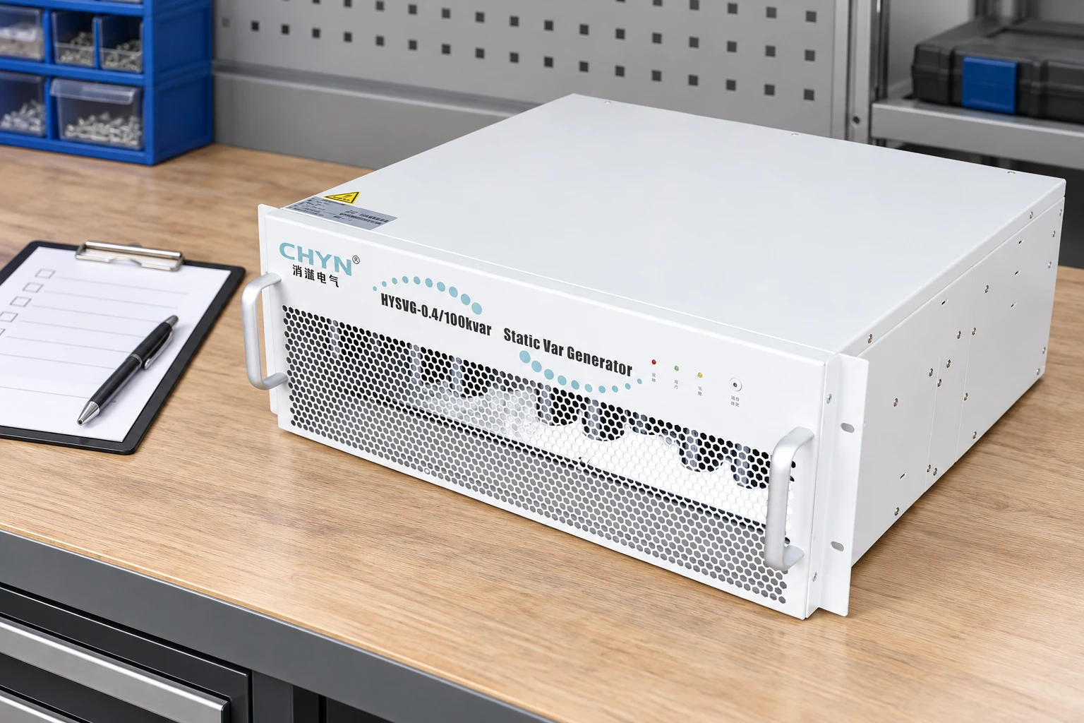
CHYN's HYSVG static var generator is the relevant product family for that discussion. Its offered functions and configuration must be confirmed in the quotation. The illustrated module is a reference to that product's appearance, not a claim that every installation uses the same module count or enclosure.
Choose AHF as the main tool when harmonic current dominates
If displacement PF is acceptable but harmonic-current measurements identify a substantial filtering duty, an AHF is a more direct starting point. Check the harmonic orders, required compensation amperes, voltage compatibility, response under changing loads, and current-transformer arrangement. Where neutral current is important, confirm the actual conductor and converter topology.
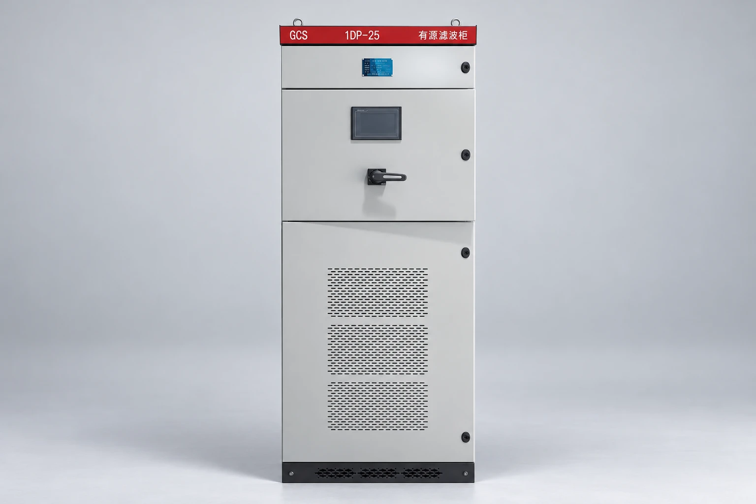
CHYN's HYAPF active power filter provides the corresponding product route. Do not assume that a quoted percentage reduction is independent of the source impedance, existing voltage distortion, load spectrum, or available filter current. Agree the input conditions and the result expected at the measurement point.
Use a combined solution when both duties matter
Some plants benefit from a multifunction converter; others need separate units or a coordinated system. Compare the simultaneous duty, spare capacity, control priorities, maintainability, and operating conditions. Adding two controllers without reviewing how they sense and respond to the same bus can produce an unclear or unstable compensation strategy.
Keep this comparison separate from the choice between active and passive filtering. That decision has its own impedance and tuning questions, addressed in the active versus passive harmonic filter guide. A passive branch is not simply a cheaper AHF with the same operating behavior.
Installation and acceptance conditions that change the result
Current-transformer position determines what the controller observes. Ask the supplier to show the CT location, polarity, ratio, phase assignment, and whether the measured current includes the compensation device. The correct arrangement depends on the control method. A product selected correctly on paper can perform poorly if its feedback does not represent the intended load.
Review existing capacitor banks, other filters, generators, transformer configurations, and future expansion. Record the ventilation, ambient temperature, altitude, access, and maintenance requirements. Cabinet dimensions do not establish clearance or airflow needs; use the approved installation drawings for the actual delivered configuration.
Acceptance should compare before-and-after measurements under comparable operating conditions. Define the reactive target, harmonic target, measurement method, monitoring period, load state, and allowable exceptions. Confirm behavior at low load and during current limiting as well as at full production. No supplier can demonstrate a meaningful improvement against an undefined baseline.
RFQ checklist: make the competing offers comparable
- State the supply voltage, frequency, earthing arrangement, one-line diagram, load schedule, and intended measurement point.
- Attach true PF, DPF, kvar, harmonic-current spectra, voltage distortion, and time-stamped operating conditions.
- Separate the required reactive compensation from harmonic filtering and any imbalance duty.
- Ask for simultaneous-function current limits, control priorities, derating, protection, and expansion provisions.
- Require CT drawings, installation conditions, a commissioning plan, and a clearly defined acceptance test.
For the underlying injection principle, see how an active harmonic filter works at its connection point. The buying decision is then straightforward to explain: specify the measured problem, allocate enough current for every required function, and verify the result where the project actually needs it.
Further learning: shunt active filtering
NPTEL IIT Delhi's lecture “Shunt Active Power Filters” explains the educational background to current compensation. It supports the functional comparison without recommending a commercial model.
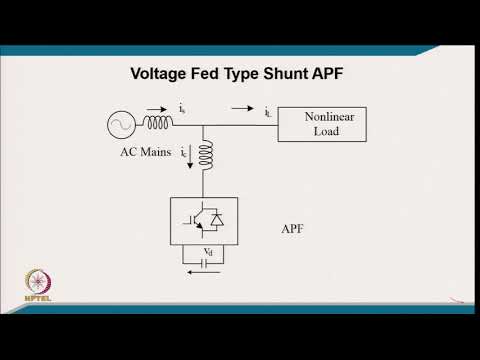
Watch Shunt Active Power Filters on YouTube.
Frequently asked questions
What is the main difference between an SVG and an AHF?
An SVG primarily supplies or absorbs reactive current. An AHF primarily compensates selected harmonic currents. Additional functions depend on the specific product and its available current.
Can an SVG also filter harmonics?
Some SVG products offer harmonic compensation, but the supported orders, current capacity, priorities, and operating conditions must be confirmed for the actual model.
Why is true power factor low when displacement PF is good?
Harmonic current increases RMS current and apparent power. True PF can therefore remain low even when the fundamental voltage-current phase relationship is close to unity.
Can one device perform full reactive and harmonic compensation simultaneously?
Only within its declared operating envelope. Request the simultaneous-function current limits, control priorities, and derating rather than assuming that separate maximum ratings are available together.