
 Zhejiang Hongyan Electric Co., Ltd.



Soft starter water hammer control must be judged by the pump system’s pressure response, not by the programmed stopping time alone. A supported pump-stopping function may improve a normal commanded stop, but its effectiveness depends on the motor, pump, valves and pipeline. It also cannot be assumed to remain available after loss of electrical power. Specify normal shutdown and power-failure events separately, obtain the relevant control-function documentation, and agree pressure-based acceptance criteria with the hydraulic designer. Do not copy a stopping curve or timer from another installation and call the surge problem solved.
Identify which event produces the pressure disturbance
Begin with the event sequence. Does the disturbance occur at startup, during a normal stop, when another pump changes state, or when incoming power fails? Record whether operators hear a valve slam, see a pressure excursion or receive a protection trip. These observations guide the investigation, but sound alone cannot identify the maximum or minimum pressure elsewhere in the pipeline. A quiet pump room does not prove that remote pipework remains within its limits.
Ask the site team to provide pump identifiers, reservoir levels, operating combinations, valve positions and the precise command that preceded the event. Preserve time-stamped controller and protection logs before resetting anything. If several pumps share a header, include the status of the others. Treat a change in reservoir level or the addition of another running pump as a different hydraulic condition rather than combining all stops into one category.
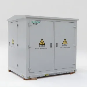
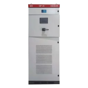
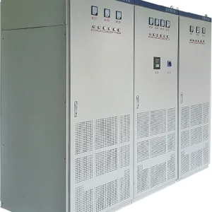
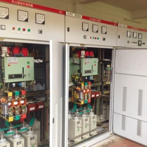
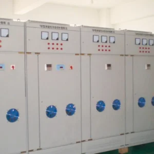
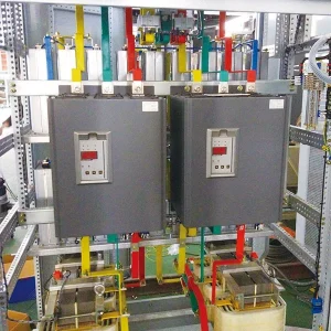
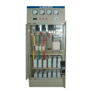
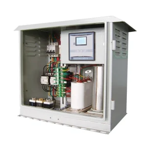
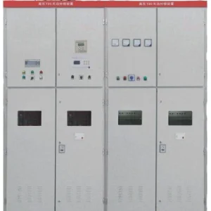
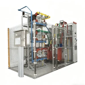
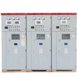
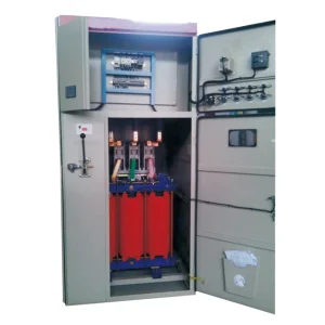
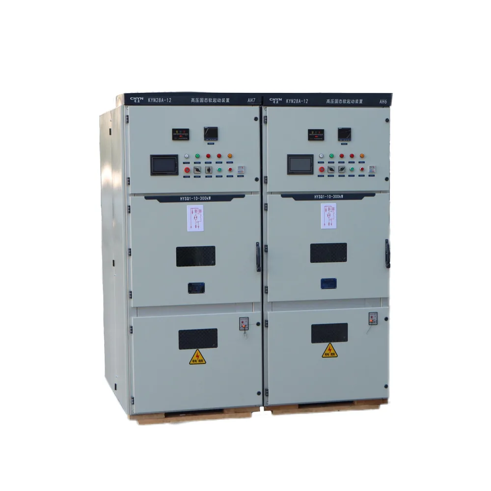
For equipment enquiries, the CHYN HYSQ1 high-voltage solid-state soft starter is a relevant product reference. Confirm the functions of the proposed configuration directly. The product photograph does not prove torque-controlled stopping, a particular pump algorithm or performance after supply failure. For the broader equipment choice, review medium-voltage soft starters and variable-frequency drives.
Keep the hydraulic and electrical questions connected
The USDA Natural Resources Conservation Service’s National Engineering Handbook chapter on pipe flow describes hydraulic transients associated with rapid changes in flow, including pump failure and valve operation. It also discusses surge-protection measures. This establishes why investigating only the electrical ramp misses part of the problem; the pipeline and its protective equipment must be included.
The City of Phoenix Water Remote Facilities Design Guidance Manual, section 5.4, treats pump shutdown and power failure as transient-analysis cases. Its municipal requirements are not universal project limits. Its useful lesson for an enquiry is to define the severe operating cases and the permitted pressure envelope before selecting a remedy.
The following discussion is a coordination and procurement guide. It is not a hydraulic model, a live adjustment procedure or a declaration that a particular CHYN starter provides any named stopping function. The pump supplier, hydraulic designer, electrical designer and equipment supplier should agree the operating sequence together.
Separate a normal stop from loss of power
During a normal commanded stop, a suitable controller may still have the supply and authority needed to execute its documented function. Request a description of what it actually controls and how the function ends. A setting labelled “deceleration” does not by itself establish a linear motor-speed ramp or a linear reduction in water flow. The supplier should explain the supported application and its limitations.
After incoming power disappears, the same controlled sequence may be unavailable. Identify what remains energized, how contactors behave and what happens to the motor and valves. Do not assume that a small backup control supply can maintain main-circuit motor torque. Ask the hydraulic designer to assess the power-loss event using the actual electrical sequence and any independent surge-control devices.
Emergency stopping also needs a distinct definition. A process stop, an electrical protection trip and an emergency stop may deliberately follow different rules. Safety functions and protective trips must retain their required behavior. A commissioning team must not delay necessary isolation merely to imitate a smooth normal shutdown. Agree the hierarchy of commands before tuning ordinary process control.
Build a shared event checklist
Use this table to organize the investigation. It offers questions and evidence categories, not universal settings or pass limits. The project team should fill in the actual sequence and acceptance criteria for each relevant operating state.
| Event | Electrical evidence | Hydraulic evidence | Decision to resolve |
|---|---|---|---|
| Normal commanded stop | Supported stop mode, current and contactor sequence | Pressure trace, valve response and initial flow | Whether the approved control sequence meets the pressure envelope |
| Incoming power failure | Supply-loss timing and remaining control power | Pump rundown, valve closure and transient assessment | Whether independent surge protection is required |
| Second pump starts or stops | Command order and running-pump status | Shared-header response at the tested operating point | Required sequencing between units |
| Restart after disturbance | Restart permissives and motor thermal state | Residual transient, air condition and valve readiness | Conditions that must be satisfied before another start |
Measure pressure and controller behavior on one timeline
A useful commissioning record should show the command, motor current, relevant status indications and hydraulic measurements against a shared time reference. Record sensor locations and sampling arrangements so the hydraulic designer can judge whether the measurements capture the event. A slow panel gauge or an averaged trend may be useful operationally while missing a short pressure excursion. Let the responsible specialist specify the instrumentation and required time resolution.
Establish a baseline under an approved, safe operating condition. Identify the starting flow, suction and discharge conditions, reservoir levels and valve state. Preserve the complete trace rather than only a screenshot of its largest value. Mark when the stop command occurred, when the motor supply changed state and when the valve response was observed. This makes a later comparison meaningful.
If field measurements disagree with the predicted response, investigate before continuing repeated trials. Check measurement scaling, clock alignment, valve behavior and whether the tested system matches the model. Do not force agreement by deleting inconvenient portions of the trace. Retain the uncertainty and assign the next verification action to the appropriate discipline.
Avoid treating a longer timer as a guaranteed solution
Ask how changes to the documented stop setting influence current, torque delivery and the final transition in this application. A larger number on the display is not independent evidence of a smoother flow change. Make adjustments only under the manufacturer’s approved procedure and with hydraulic limits in place. Define a stopping point for the trial if pressure, current, vibration or another monitored condition exceeds its agreed boundary.
Consider the motor’s thermal duty when repeated commissioning stops require repeated starts. Keep an attempt log and respect the approved recovery conditions. A sequence that seems acceptable once may not establish repeat-operation suitability. The article on soft starter starting duty explains why current, duration and thermal state must accompany a starts-per-hour figure.
Do not confuse stopping control with acceleration setup. A successful start does not approve a stop, and a smooth normal stop does not approve an emergency event. Review soft starter acceleration-time selection separately when preparing the full operating sequence. Keep the acceptance results attached to the mode and operating condition actually tested.
Prepare an enquiry that suppliers can answer precisely
Send the motor nameplate data, supply voltage and frequency, pump performance information, anticipated operating range and the hydraulic assessment. Include the required start and stop sequence, the number of pumps, any shared header, control-valve arrangement and communications interfaces. Identify which signals are hardwired and which depend on a supervisory system. Request a sequence diagram showing how the proposed starter exchanges commands and permissives with the station controls.
Require the quotation to identify the stopping function by its actual documented name and list any necessary options. Ask what happens on loss of the main supply, control power, communications or a valve-ready signal. Include the required alarm records and setting backup. If the supplier cannot substantiate a function, keep it as an open technical exception rather than substituting a general statement about smooth operation.
Allocate responsibility for surge performance explicitly. The starter supplier can confirm its electrical capabilities, while the hydraulic designer must assess how those capabilities interact with the water system. If a valve change, surge vessel or another measure is proposed, update the system assessment before approving it. A collection of individually suitable components does not automatically establish a suitable combined sequence.
Close commissioning with repeatable records
The handover should contain the approved settings, tested operating cases, pressure records, controller logs and unresolved restrictions. Label normal stop and supply-failure results separately. Record the conditions under which a restart is allowed and the operator action required after an abnormal event. These instructions should be available at the station, not hidden in an email chain.
Repeat the relevant engineering review after significant changes to pumps, valves, pipework or control logic. Retain a baseline trace for future comparison and record modifications against it. If the operating range expands beyond the tested conditions, obtain an assessment before treating the earlier result as applicable. Water hammer control remains a system responsibility throughout the installation’s life.
Educational background: water hammer and surge tanks
The following NPTEL lecture by Dr. Arup Kumar Sarma of IIT Guwahati explains water hammer and surge tanks. It supports discussion of hydraulic transients; it is not a CHYN starter setup guide or a demonstration of an approved stopping curve.
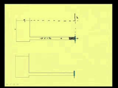
Watch the educational lecture on YouTube.
Frequently asked questions
Will every soft starter eliminate water hammer?
No. Confirm the supported stopping function and assess the complete pump and pipeline system. Accept the result against agreed pressure criteria rather than the presence of a soft-stop setting.
Does extending the stopping time always help?
No. The setting alone does not establish the flow response. Evaluate approved changes using pressure and electrical records while respecting motor duty and the project’s stopping criteria.
Does normal soft stopping protect against a power failure?
It cannot be assumed. Establish what control remains available after supply loss and assess the resulting pump rundown and valve response as a separate hydraulic event.
What information is most useful for a pump-starter enquiry?
Provide motor and supply data, pump curves, operating combinations, valve details, hydraulic transient requirements and the intended control sequence. Request documented stopping functions and explicit power-loss behavior.