
 Zhejiang Hongyan Electric Co., Ltd.






































A 7% detuned reactor is matched to a capacitor so that the reactor's fundamental-frequency reactance equals 7% of the capacitor's reactance. In the ideal series LC model, that combination resonates at about 189 Hz on a 50 Hz supply, or 227 Hz on a 60 Hz supply. The 7% figure does not mean 7% energy loss or a guaranteed 7% reduction in harmonics. It also changes capacitor terminal voltage and the net kvar delivered by the step. Those changes must be included when selecting the reactor, capacitor, switching components, and protection.
What the 7% rating actually defines
Let XL1 be the reactor's inductive reactance and XC1 the capacitor's capacitive reactance at the fundamental supply frequency f1. The detuning factor is p = XL1 / XC1. For a 7% combination, p = 0.07. The percentage applies to a specified reactor-capacitor pair at a specified frequency, not to the coil in isolation.
Since XL1 = 2πf1L and XC1 = 1 / (2πf1C), p = (2πf1)²LC. Changing the capacitance or the operating frequency changes the ratio even if the physical reactor remains the same. A spare coil described only as “7%” therefore cannot be approved without checking its matching conditions.
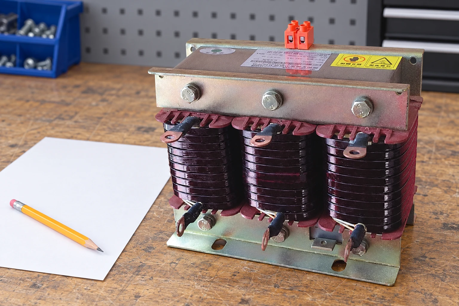
This article deals with interpreting and checking that numerical pairing. For the broader reasons a bank may need inductance, including inrush limitation, use the guide to why reactors are used with capacitor banks. A small inrush-limiting reactor and a deliberately detuned compensation branch are different selection duties.
Why 7% gives 189 Hz at 50 Hz
The ideal series resonance condition is XL = XC, giving fr = 1 / (2π√LC). Combining this with the definition of p gives fr = f1 / √p. The following values are calculations from that relationship, rounded to the nearest hertz. They are not measured performance data for a particular product.
| Detuning factor | Calculated resonance at 50 Hz | Calculated resonance at 60 Hz | Fundamental capacitor-voltage multiplier |
|---|---|---|---|
| 5.67% | 210 Hz | 252 Hz | 1.060 |
| 7% | 189 Hz | 227 Hz | 1.075 |
| 14% | 134 Hz | 160 Hz | 1.163 |
The underlying resonance relationship is explained in OpenStax University Physics, Resonance in an AC Circuit. The voltage multipliers follow the ideal fundamental-frequency derivation below. Resistance, component tolerances, harmonic voltages, and network interactions require a fuller study.
For p = 0.07, the resonance order relative to the fundamental is 1 / √0.07 ≈ 3.78. It is below the fifth harmonic, which is 250 Hz on a 50 Hz supply and 300 Hz on a 60 Hz supply. It is above the third harmonic. The position alone does not prove suitability when third-harmonic or other low-frequency components are significant.
Detuning does not eliminate every resonance in the installation
At the fundamental frequency, the matched branch remains capacitive because the capacitor reactance is larger than the reactor reactance. Above its series resonant frequency, the branch becomes inductive in the ideal model. This changes its interaction with higher-frequency components compared with a bare capacitor step.
The branch still has a resonance, and the wider network has its own impedances. Transformer impedance, upstream supply strength, other capacitor steps, generators, and cables can change the overall frequency response. A design should avoid harmful amplification across the credible operating configurations, rather than treating the word “detuned” as a universal guarantee.
A detuned power-factor-correction bank should also be distinguished from a deliberately tuned harmonic filter. Both use inductance and capacitance, but the specified objective, harmonic loading, component duty, and acceptance criteria differ. If the project requires a defined reduction in particular harmonic currents, request a filtering study and explicit performance conditions.
Why the capacitor sees more voltage than the branch supply
In the ideal fundamental-frequency series circuit, the inductor and capacitor voltage drops oppose each other. The applied branch voltage is Us = I(XC1 − XL1). The capacitor terminal voltage is UC = IXC1. Therefore UC = Us / (1 − p).
For an illustrative delta-connected branch supplied at 400 V with p = 0.07, the calculated capacitor terminal voltage is 400 / 0.93 ≈ 430.1 V at the fundamental. The reactor's opposing fundamental voltage is about 30.1 V. The 7% factor describes reactance relative to the capacitor; it is not simply a 28 V deduction from a 400 V capacitor rating.
That calculation is not sufficient to approve a 440 V capacitor. Maximum system voltage, harmonic content, permissible duty, capacitance tolerance, temperature, and the manufacturer's pairing rules must also be considered. A star-connected arrangement uses the applicable phase-branch voltage; do not substitute line-to-line voltage without checking the actual connection.
The official scope of IEC 60831-1 covers self-healing shunt power capacitors for AC systems up to and including 1000 V, including relevant filter applications. The standard reference does not by itself establish a particular capacitor's compatibility with a reactor or certify the complete compensation panel.
Calculate net kvar using the capacitor's own nameplate basis
Net compensation output is frequently confused with capacitor nameplate kvar. For the same capacitance, capacitor kvar changes with the square of voltage at a fixed frequency. A capacitor rated at a higher voltage produces less kvar when connected at a lower voltage unless the branch current and reactor are accounted for correctly.
For an ideal balanced three-phase example, let QN be the total capacitor-set nameplate kvar at its rated voltage UN and the specified fundamental frequency. Let Us be the corresponding system voltage basis for the same connection. The net capacitive output of the matched series branch is Qnet = QN(Us/UN)² / (1 − p).
Consider a hypothetical capacitor set rated 50 kvar at 440 V and 50 Hz, matched to a 7% reactor on a 400 V, 50 Hz system. Its net output is 50 × (400/440)² / 0.93 ≈ 44.4 kvar. The fundamental line current of that complete balanced step is approximately 44,400 / (√3 × 400) ≈ 64.1 A. This is an educational example, not a CHYN catalogue pairing.
The 64.1 A figure is the line current, not automatically the current in every winding of a delta-connected reactor assembly. The manufacturer's winding connection and current-rating convention matter. Harmonic RMS current, tolerances, saturation, ventilation, and protection margins must be added through the engineering selection process.
If the intended net step is 50 kvar, a 50 kvar capacitor nameplate at a different voltage is not enough information to order. Request a matched table that states capacitor rated voltage, capacitance, reactor inductance, detuning factor, net output at system voltage, and continuous current duty. This prevents two suppliers from quoting different electrical outputs under the same informal step label.
Match the coil, capacitor, and operating conditions as one set
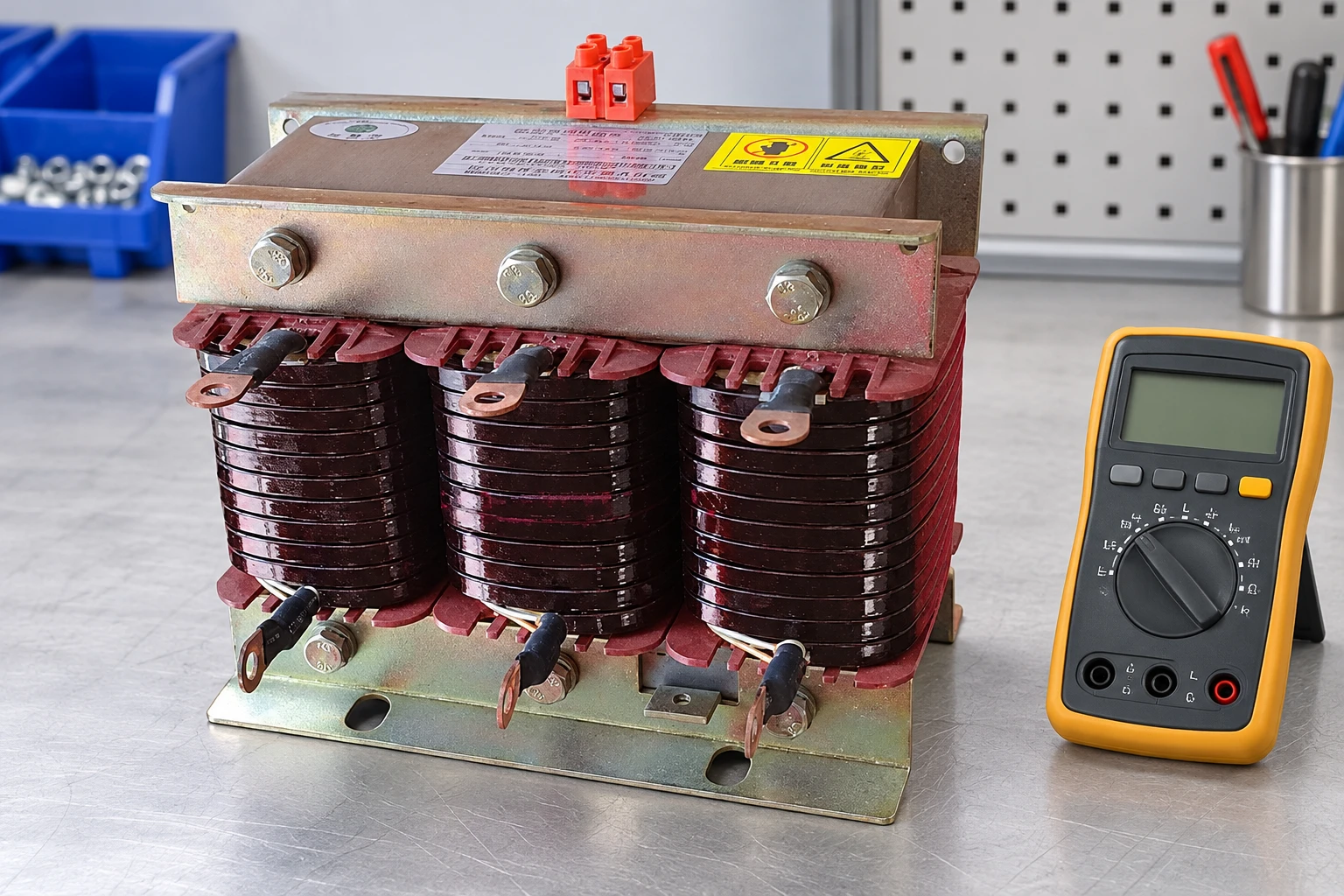
CHYN's CKS series detuned and tuning reactors are the relevant product family for a pairing inquiry. The website lists several detuning options. The reference photograph identifies the visible product structure; it does not establish the inductance, current, or detuning factor of the exact photographed unit.
Ask for inductance at the relevant current, inductance tolerance, linearity or saturation information, allowable harmonic-current duty, winding temperature protection, insulation system, and cooling requirements. Confirm whether the catalogue kvar designation refers to the matching capacitor nameplate or the completed branch's net output. Both conventions occur, so the written pairing table is more useful than an isolated model label.
Frequency deserves an explicit check. Keeping the same L and C while moving from 50 to 60 Hz increases the fundamental reactance ratio by (60/50)² = 1.44. A pair that was 7% at 50 Hz would be about 10.08% at 60 Hz, even though its physical LC resonant frequency is unchanged. The table above assumes each pair is designed to have the stated percentage at its own supply frequency.
IEC 60076-6 includes filter or tuning reactors among its covered reactor types. Use the applicable standard edition and declared test requirements in the technical specification, while obtaining actual product test and rating documents from the supplier.
Commissioning checks that reveal a pairing error
Commissioning should verify the delivered components against the approved pairing schedule before energization. Record each step's capacitor details, reactor identity, wiring connection, switching arrangement, protection, and temperature-sensor circuit. Visual similarity is not evidence that an available spare coil is electrically equivalent.
With qualified personnel and an approved procedure, verify the intended step operation, phase currents, capacitor and reactor loading, thermal behavior, and harmonic measurements under representative conditions. Compare the measured output with the expected net kvar at the actual voltage. A discrepancy can arise from voltage variation, wrong capacitance, incorrect connection, failed components, or a mistaken nameplate basis.
Keep the safety and test procedure separate from this selection calculation. Capacitors retain stored energy after disconnection. The existing capacitor bank testing guide and the manufacturer's instructions provide the next level of context; an arithmetic result never authorizes live work.
What to include in a 7% reactor inquiry
- System nominal and maximum voltage, frequency, connection diagram, earthing arrangement, and credible operating configurations.
- Desired net kvar per step and the actual capacitor voltage, kvar, capacitance, and frequency basis.
- Harmonic voltage and current spectrum, transformer and source information, and existing compensation equipment.
- Required matching table, current and thermal duty, inductance tolerance, protection, installation conditions, and spare-part references.
- Acceptance criteria for net kvar, phase balance, temperature, and the agreed harmonic behavior.
For the overall bank-capacity calculation, use the capacitor bank sizing guide. The purpose here is to make sure a selected 7% pair delivers that required output without overlooking its increased capacitor voltage or actual component duty.
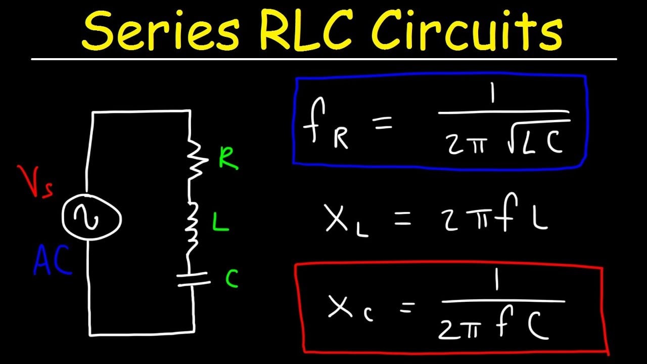
Further learning: LC series resonance
The Organic Chemistry Tutor's lesson on series RLC circuits explains inductive reactance, capacitive reactance, and resonant frequency. It supplies circuit-theory background, not a field wiring procedure or a product recommendation.
Frequently asked questions
What does 7% mean on a detuned reactor selection?
It means the reactor fundamental reactance is 7% of its matched capacitor reactance at the specified operating frequency. It is not an efficiency loss or a guaranteed harmonic reduction.
Why is a 7% combination called 189 Hz?
For a pair designed to have p = 0.07 at 50 Hz, the ideal series resonant frequency is 50 divided by the square root of 0.07, approximately 189 Hz.
Can a 400 V capacitor be assumed suitable on a 400 V detuned branch?
No. In the ideal 7% example, the capacitor fundamental terminal voltage is approximately 430.1 V. Selection must also consider the actual voltage range, harmonics, tolerances, and manufacturer pairing requirements.
Does a 50 kvar capacitor always give a 50 kvar detuned step?
No. Net output depends on capacitor rated voltage and capacitance, system voltage, frequency, and reactor pairing. Request the matched net-kvar table rather than ordering from the capacitor kvar label alone.