
 Zhejiang Hongyan Electric Co., Ltd.






































PLC voltage sag troubleshooting starts by establishing which device actually lost its required supply. Record the incoming AC voltage, the control power supply's output, and the PLC or machine event sequence on a common time base. A line can stop because a contactor or remote I/O device drops out even while the PLC CPU stays running. Once that failure path is known, choose between correcting the source, supporting the control circuit, or protecting the production load. Installing a harmonic filter or capacitor bank without this evidence can leave the original stoppage unchanged.
First distinguish a PLC reset from a process stop
“The PLC tripped” is often an operator's description of a stopped machine rather than a diagnosis. Retrieve CPU diagnostics, power-supply indicators, drive fault histories, safety-system events, and operator messages. Identify the earliest trustworthy event. A communication timeout after a power loss is a consequence, while a recorded undervoltage before that timeout may reveal the initiating condition.
Separate four possibilities: the CPU rebooted; the CPU remained healthy but remote I/O disappeared; a contactor or drive dropped out; or a safety function intentionally stopped the equipment. These paths have different remedies. Never bypass a safety circuit or extend a protective delay merely to make the line continue running.
The broader manufacturing plant power quality solution provides system context. This guide narrows the investigation to the evidence required for a supply-related stoppage, rather than attempting to cover every cause of poor electrical power quality.
Capture the disturbance where it matters
A handheld meter reading taken after restart cannot establish what happened during a short event. A useful recording shows the voltage remaining during the sag, its duration, the phases affected, and the sequence of recovery. Waveforms may reveal details hidden by a long averaging interval. Set the recorder and event triggers for the problem being investigated.
Start at the machine or control-panel supply, then compare it with an upstream measurement when practical. If only the downstream point dips, investigate the local feeder and loading. If both dip together, the source is farther upstream or the event is shared. This is localization evidence, not automatic proof that the electricity supplier is responsible.
Include the AC input to the control power supply and its DC output. A sag at the AC input may be bridged by stored energy in the supply, while a healthy AC input with a DC collapse points elsewhere. Use suitable isolated measurement equipment and qualified personnel. Do not connect an ordinary grounded oscilloscope across mains conductors.
Synchronization is essential. PLC logs, drive logs, and power-quality recorders may use different clocks or time zones. Document their offsets before interpreting event order. When timestamps are coarse, treat apparently simultaneous messages as a group and use waveforms or faster event records to establish causation.
A practical symptom-to-measurement table
| Observed pattern | Next evidence to obtain | Possible direction, subject to confirmation |
|---|---|---|
| CPU restarts during an AC dip | Power-supply input, DC output, load current, CPU power-loss record | Check supply hold-up and whether the whole control chain needs support. |
| CPU stays on; drive records undervoltage | Drive input event and its documented ride-through behavior | Evaluate drive or feeder protection; a CPU-only UPS may not preserve production. |
| Only remote I/O disappears | Remote DC supply, network switch supply, and connection diagnostics | Investigate distributed power and communications before replacing the CPU. |
| DC dips when a solenoid operates; AC stays steady | DC branch voltage and current at the event | Investigate overload, wiring drop, branch segregation, or supply condition. |
| Several machines stop at the same instant | Synchronized upstream and downstream voltage records | Investigate a common supply event and the most sensitive shared component. |
The table is an investigation framework, not a set of universal equipment limits. LADWP's power-quality guidance identifies monitoring as a way to detect sags and distinguishes surge protection, UPS support, and sag correction. Each device's actual operating limits must come from its own documentation.
Follow the 24 V control power path
Many industrial controllers use nominal 24 V DC, but the acceptable voltage range, hold-up time, and restart behavior are model dependent. Read the exact power-supply, CPU, I/O, and sensor specifications. A nominal label alone says nothing about how long a device tolerates a particular disturbance.
Trace the supply through branch protection, distribution terminals, remote cabinets, network switches, contactor coils, and field devices. Measure at the affected device as well as at the power supply. A good supply-terminal voltage can coexist with excessive drop in a long cable or a poor connection downstream.
Record steady and peak DC demand. A coil, brake, or actuator may create a brief load increase that the supply or branch cannot support. Separate load-induced DC droop from an AC sag before choosing equipment. An AC voltage restorer cannot repair an undersized DC branch or a damaged terminal.
Temperature, loading, supply age, and installed accessories can affect available hold-up. Ask for evidence under the intended conditions rather than a typical no-load figure. Supporting only the CPU may preserve its memory while the remote I/O, Ethernet switch, or contactor still drops out and forces a line restart.
Use one event to build a testable explanation
Consider a hypothetical 400 V line-to-line machine supply that falls to 280 V for 120 ms. The remaining voltage is 280 / 400 = 0.70 per unit, or 70% of nominal. This describes the disturbance at that measurement point; it does not establish whether a particular PLC or power supply should survive it.
Suppose the CPU records no restart, but a drive reports DC-bus undervoltage before the PLC receives “drive not ready.” The investigation should follow the drive and the process sequence. Adding backup power to the CPU alone would not address the demonstrated failure path. Conversely, if the AC input dip is bridged successfully but the remote DC supply collapses with a load change, the corrective work belongs in the remote control-power circuit.
Document what the evidence proves and what remains uncertain. One captured event may justify a localized repair, but it may not represent the worst sag the site experiences. Before specifying a plant-wide system, collect enough events to define the credible depth, duration, affected phases, and process consequences.
Choose protection to match the affected boundary
Control-circuit support
A DC buffer or DC UPS may be appropriate when the vulnerable loads are a defined control circuit. List every device required to preserve the intended machine state, including switches and distributed I/O. Check load peaks, output voltage, usable stored energy, recharge requirements, temperature, end-of-life assumptions, alarms, and the behavior during an extended loss of supply.
The ideal energy relation E = P × t is useful only as an initial estimate. A hypothetical 120 W control load needing 0.5 seconds requires 60 joules at the load before losses and reserve. Real storage selection must allow for conversion efficiency, minimum output voltage, aging, and transient demand. This calculation is not a battery or capacitor product rating.
Machine or feeder voltage-sag mitigation
If a drive, contactor group, or complete production process must remain supplied, protection may need to cover more than the control circuit. A dynamic voltage restorer injects compensating voltage in series with the load supply within its designed envelope. Confirm supported sag depth, duration, phase conditions, recovery, available energy, bypass behavior, and downstream fault coordination.
CHYN's HYDVR voltage sag mitigation range is a relevant starting point for this discussion. Do not select a cabinet from kVA alone or assume a sag corrector covers a complete interruption. Request a guaranteed operating envelope for the measured event profile and the actual load.
Source and distribution corrections
Where measurements identify a local starting load, weak feeder, poor connection, or transformer constraint, correct that cause where practical. Possible engineering responses include feeder repairs, starting-method changes, load sequencing, or a distribution redesign. The choice depends on the measured network and process requirements; equipment should not be added simply because an event occurred near a motor start.
Why a capacitor bank, SVG, or AHF may leave the trip unchanged
A capacitor bank supplies reactive power. An SVG controls reactive current, and an active harmonic filter addresses selected current distortion duties within its rating. These functions can improve relevant aspects of the electrical system, but they do not automatically provide stored active energy to sustain a sensitive process through any upstream fault or interruption.
A project may require more than one solution. Harmonic mitigation and sag ride-through should have separate measured objectives and acceptance tests. Use the guide to causes of power quality problems to distinguish disturbances, and how an active harmonic filter works when current distortion is independently confirmed.
Commissioning: demonstrate that the process survives
Agree on success before ordering: no CPU reboot, no loss of essential I/O, no unintended contactor dropout, no drive undervoltage stop, and no unsafe restart. The criteria should match the intended protected boundary. Maintaining voltage at a cabinet's output is necessary evidence, but it is not sufficient if an unprotected remote device still stops the process.
Have qualified engineers plan any controlled disturbance or ride-through testing with the machine builder and production team. Test methods must preserve safety functions and consider process hazards. OSHA's electrical work-practice requirements describe isolation and qualified work around electrical hazards; the site's governing local rules and approved procedures also apply.
Record the input event, protected output, equipment alarms, and process result. Include recovery, repeated events where required, depleted-storage behavior, bypass, and a controlled extended outage response. Retain the before-and-after records so future maintenance can confirm that the original failure mode remains addressed.
What to send with a technical inquiry
- Provide the one-line diagram, nominal supply, earthing system, feeder arrangement, and proposed protection boundary.
- Attach event recordings with remaining voltage, duration, phases affected, waveforms, and timestamp reference.
- List the CPU, power supplies, drives, remote I/O, network devices, contactors, and their documented supply limits.
- State continuous and peak loads, required survival time, restart behavior, and the production cost of a stoppage.
- Request the supported disturbance envelope, energy assumptions, bypass and fault behavior, installation requirements, and process acceptance test.
For a wider monitoring plan, see what power quality monitoring can establish. A useful inquiry explains the event and the failed component before asking for a cabinet. That gives the supplier a checkable engineering problem and helps prevent a technically impressive solution from protecting the wrong part of the machine.
Further learning: sag mitigation and ride-through
The following lecture, “L19 Mitigating Sags and Interruptions,” is presented on electrical engineering educator Salman Mohagheghi's channel. It explains mitigation principles; it is supplementary education rather than a product endorsement or a substitute for machine-specific validation.
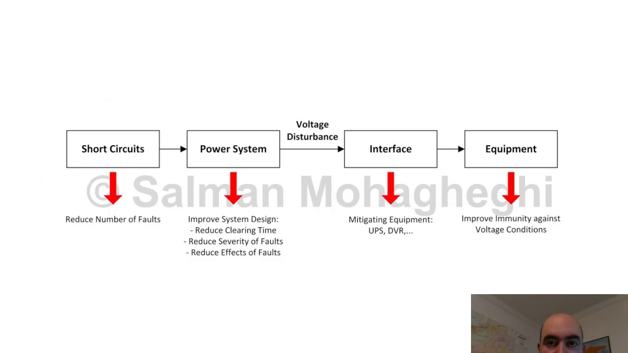
Watch L19 Mitigating Sags and Interruptions on YouTube.
Frequently asked questions
Can a voltage sag stop a machine without restarting the PLC?
Yes. A contactor, drive, remote I/O supply, or network device can lose its required supply while the CPU remains on. Check the first event in the recorded sequence.
Will a UPS for the PLC CPU prevent every line trip?
No. It protects only the loads connected to it. The process may still stop if an essential drive, contactor, remote I/O module, or communications switch is unsupported.
Does a harmonic filter fix voltage-sag trips?
Not automatically. A harmonic filter addresses current distortion within its rating; a sag-related supply failure needs a remedy matched to the measured depth, duration, and affected equipment.
What measurements should I send to a sag-mitigation supplier?
Provide synchronized voltage recordings, event duration and affected phases, AC and DC supply data, equipment logs, the one-line diagram, load information, and the required process ride-through behavior.