
 Zhejiang Hongyan Electric Co., Ltd.
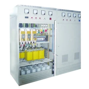
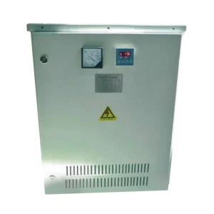
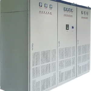
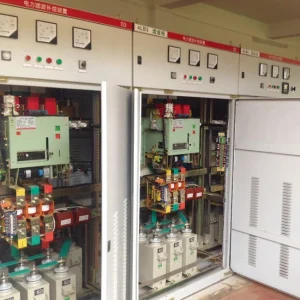
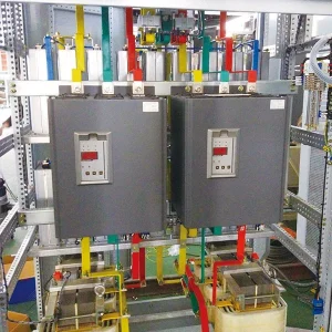
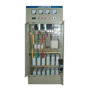
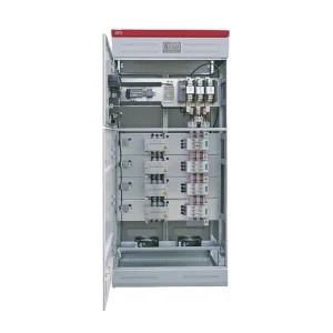
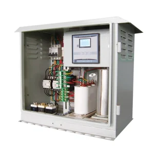
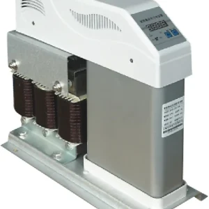
THD vs TDD is a comparison of reference currents. Current total harmonic distortion describes harmonic current relative to the fundamental current measured during the same interval. Total demand distortion uses an established maximum demand reference. The same harmonic amperes can therefore produce different percentages. Before sizing an active harmonic filter, record the actual current spectrum, the operating load, the measurement boundary and the demand-current definition. A percentage alone cannot establish how many amperes must be compensated or whether a contractual harmonic requirement has been met.
This guide is for engineers and buyers reviewing a harmonic survey or filter proposal. It explains the calculation, shows why low-load readings can mislead, and provides an evidence checklist for a defensible acceptance test.
Start with the measurement boundary
A drive feeder, a distribution board and the point of common coupling are different measurement locations. A feeder can have a high distorted-current percentage while representing a small share of site demand. Conversely, a large plant can have substantial harmonic amperes even when a percentage appears modest. Label every result with the physical bus, CT location, CT ratio, phase and timestamp. Do not compare two reports until these identifiers match.
The boundary also determines which loads are included. If a survey is taken downstream of one production line and the proposed filter is installed upstream of several lines, the measured spectrum is incomplete for that installation. Include existing capacitor banks and their switching states in the single-line diagram because network configuration can influence the observed harmonic conditions.
Calculate the two percentages consistently
For a stated set of harmonic orders, let H be the root-sum-square harmonic current in amperes: H = √(I₂² + I₃² + … + Iₙ²). Let I₁ be the simultaneous fundamental current, also in amperes, and let IL be the approved maximum demand reference current. Then current THD = 100H/I₁, while TDD = 100H/IL. The numerator and denominator must refer to compatible phase and measurement conventions.
IEEE’s technical overview of total harmonic distortion explains the fundamental-current denominator and the demand-current alternative. The overview supports the distinction; the applicable standard and agreement must establish the complete assessment method.
Meter terminology deserves attention. Some instruments also provide a distortion value referenced to total RMS current, rather than the fundamental. That reading is mathematically different. Export the channel description or meter configuration, not just a screenshot showing “THD.” Also distinguish voltage distortion from current distortion: their quantities, units and engineering uses are different.
A worked example: identical harmonic amperes, different THD
Consider an illustrative survey with H = 20 A and an agreed demand reference of 200 A. During one operating interval the fundamental current is 100 A; during another it falls to 50 A. Keeping the harmonic current unchanged isolates the effect of the denominator. These values are teaching inputs, not CHYN product ratings, test results or compliance limits.
| Illustrative state | Harmonic RMS sum H (A) | Fundamental I₁ (A) | Demand reference IL (A) | Current THD (%) | TDD (%) |
|---|---|---|---|---|---|
| Higher load | 20 | 100 | 200 | 20 | 10 |
| Lower load | 20 | 50 | 200 | 40 | 10 |
| Different harmonic condition | 30 | 100 | 200 | 30 | 15 |
The table is calculated using the equations above. In the second row, THD doubles without an increase in harmonic amperes. In the third row, both the harmonic current and TDD increase. Neither comparison establishes compliance until the applicable limits, harmonic-order range, evaluation period and measurement boundary are specified.
A useful review question is therefore: “Did the numerator change, the denominator change, or both?” Plotting fundamental current alongside harmonic amperes makes this much easier to answer than comparing percentage peaks alone.
Establish the demand reference before interpreting TDD
Request the method used to establish IL, the source records and the assessment period. A configured meter constant, a current-transformer rating and an observed short-term peak are not automatically interchangeable. The responsible engineer should confirm the definition required for the project, especially when historical demand records are incomplete or the facility has recently expanded.
Record whether the demand reference is phase-specific, how missing data are handled and whether plant operating conditions changed during the reference period. A new line, a transformer replacement or a change in generation can make an old reference unsuitable for a new agreement. Keep the approved reference with the report so another reviewer can reproduce the calculation.
For detailed measurement background, Yokogawa’s harmonic-measurement application note presents harmonic analysis and the use of a maximum-demand reference for TDD. Instrument documentation helps explain channel behavior; it does not select a site’s contractual acceptance limit.
Translate the survey into an active-filter requirement
Filter selection needs the current spectrum in amperes for each relevant phase and operating state. Identify the harmonic orders requiring attention, the expected load combinations and the measurement location at which performance will be assessed. Ask the supplier to state how its proposed compensation relates to these inputs, rather than converting a THD percentage directly into a catalog current rating.
Also identify concurrent duties. If a proposed device is expected to support reactive power or load balancing as well as harmonic compensation, request the allocation and priority rules. Available capability under combined duties must be documented for the actual model. Do not assume that separately quoted functions can all deliver their maximum output simultaneously.
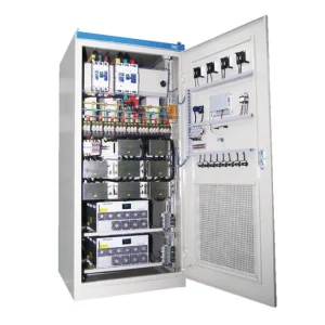
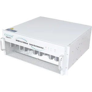
CHYN’s HYAPF active power filter product page is a starting point for a project discussion. Supply the survey, single-line diagram and operating envelope when requesting selection. No capacity or harmonic-performance guarantee is established by the illustrative arithmetic in this article.
Write an acceptance test that can be repeated
Agree on the test plan before purchase. Define the measurement boundary, instrument configuration, recording duration and operating states. Capture a baseline and a compensated condition with comparable plant operation. A before-and-after image taken at different production levels can show a changed percentage without demonstrating the expected reduction in harmonic current.
Keep the original data files as well as the report. For each state, include phase currents, harmonic spectra, fundamental current, voltage distortion, demand reference, capacitor-bank state and relevant alarms. If the instrument applies aggregation or statistical reporting, document those settings. A future investigation should not depend on reconstructing them from an unlabeled chart.
Agree how unavailable operating states will be handled. If the plant cannot reach its planned maximum production during commissioning, record which tests remain outstanding and who will complete them. Acceptance for a limited operating envelope should say so explicitly. It should not silently become a claim for every future load combination.
Common errors in harmonic reports
- Using a feeder percentage as a site result: confirm the actual PCC and distinguish internal equipment checks from site-level evaluation.
- Treating a low TDD as proof of zero risk: inspect harmonic amperes, component duty and local voltage distortion as well.
- Changing the demand reference between tests: retain one approved basis when comparing the same acceptance requirement.
- Reporting one phase only: evaluate all relevant phases and identify the limiting condition.
- Promising compliance from a single snapshot: use the agreed recording and evaluation procedure.
A report should make these distinctions easy to audit. Ask for a one-page measurement map that connects each chart to a physical location and each percentage to its denominator. This small addition often resolves disagreements that would otherwise be blamed on the filter.
Prepare the inquiry package
Send the supplier a marked single-line diagram, CT and voltage-channel information, raw survey files, expected load growth, existing compensation details and the target assessment method. Include site temperature, installation constraints and service access requirements. Ask for a written statement of assumptions, excluded operating conditions and the evidence needed for final selection.
For broader context, begin with CHYN’s explanation of active harmonic filter operation. The SVG and active harmonic filter comparison addresses different compensation objectives, while third-harmonic neutral current explains a complementary issue in four-wire systems.
Educational video: active-filter operating principle
“Shunt Active Power Filters” from NPTEL IIT Delhi explains the compensation principle behind an active filter. Use it as conceptual background when reviewing a proposal; the project measurement plan and selected equipment documentation govern acceptance.
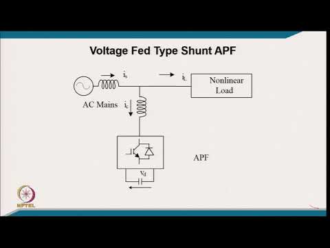
Watch Shunt Active Power Filters on YouTube.
Record the decision behind the selected target
The project file should explain why the chosen metric is being used. A utility requirement, an equipment concern and an internal improvement objective can lead to different acceptance questions. Identify the owner of each requirement and the evidence needed to close it. If several requirements apply, report them separately rather than compressing everything into one green or red percentage.
Also retain the agreed harmonic-order range and treatment of missing data. A report generated with different analyzer settings may otherwise appear to contradict the commissioning baseline. Consistent settings and named assumptions make later comparisons useful when production expands or another nonlinear load is added.
Frequently asked questions
Can current THD rise when harmonic amperes stay unchanged?
Yes. Current THD uses the simultaneous fundamental current as its denominator. If that fundamental current falls while the harmonic RMS sum stays unchanged, the percentage rises. Review the actual amperes and load state before concluding that harmonic injection has increased.
Can I substitute the CT rating for the TDD demand reference?
Not automatically. The demand reference must be established using the method required by the applicable assessment or agreement. A CT ratio describes the measurement arrangement; it does not by itself establish the maximum demand load current for that assessment.
Does a low TDD prove an active filter is unnecessary?
No. TDD is one part of the assessment. Review the harmonic spectrum, local voltage distortion, component duty, operating states and the agreed measurement boundary. A site-level percentage does not answer every equipment-level performance or heating question.
Can I size an active filter from the largest THD percentage?
No. Obtain harmonic currents in amperes across representative states, identify the required compensation and confirm any concurrent duties. Selection also needs the network arrangement, installation conditions and documented capability of the actual proposed configuration.