
 Zhejiang Hongyan Electric Co., Ltd.
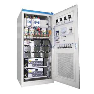
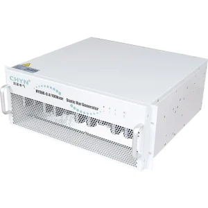
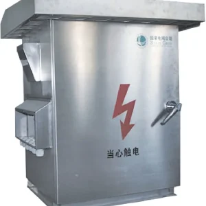
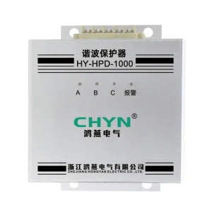
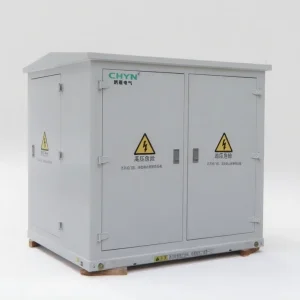
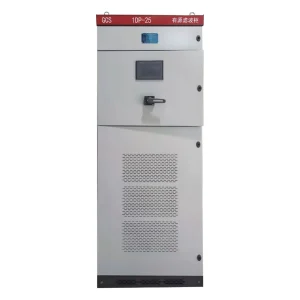
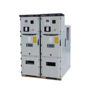
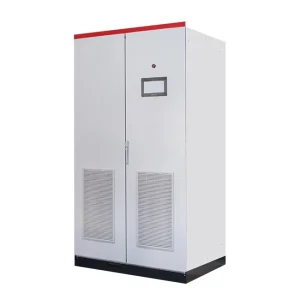
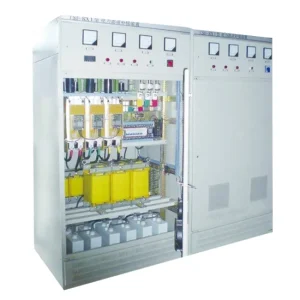
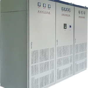
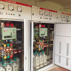
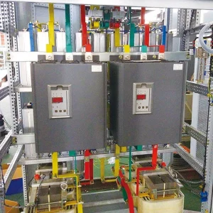
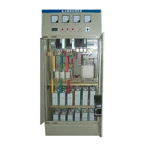
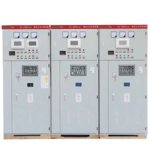
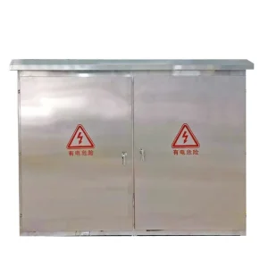
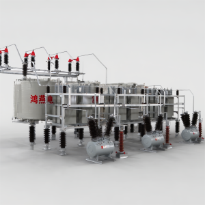
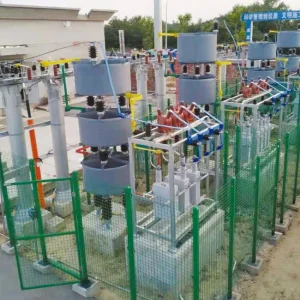
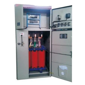
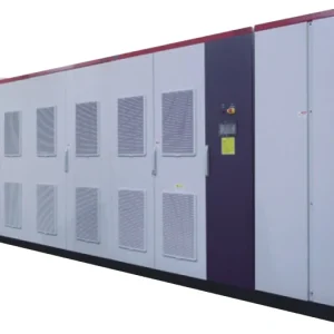
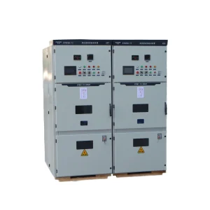
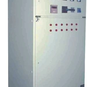
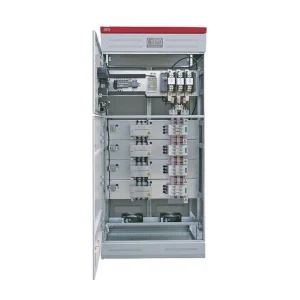
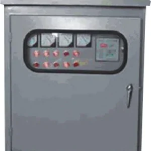
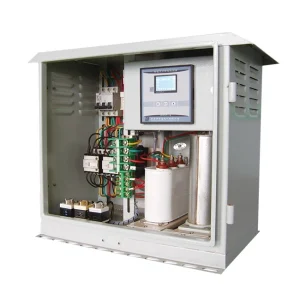
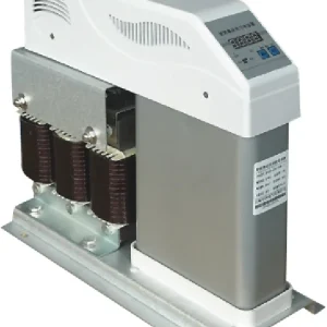
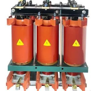
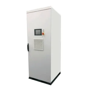
APFC panel hunting is repeated capacitor-step switching caused by an unstable or unsuitable control response rather than a useful correction of the actual load. The first task is to distinguish true hunting from legitimate load changes, normal step rotation, and repeated protection or restart events. Record the controller's commands, actual step feedback, signed kW and kvar, voltage, and alarms on a common time base. Then check sensing, step size, control band, delays, and component condition. Increasing a delay or replacing the relay without this evidence can hide the symptom while leaving the cause unresolved.
Confirm that the repeated switching is actually hunting
A bank can legitimately switch often when reactive demand changes often and the complete system is designed for that duty. A controller may also rotate healthy steps to distribute operating hours. Neither observation alone proves an unstable feedback loop.
Suspect hunting when the same step repeatedly connects and disconnects under an otherwise similar load state, especially when its own effect moves the measured quantity across opposing switching thresholds. A different pattern may arise when a step trips on protection, resets, and is commanded again. That is an alarm and component-duty investigation rather than simply a deadband problem.
Start with the event sequence. Identify which command occurs first, whether the device actually changes state, what happens to reactive power, and whether an alarm or permissive change intervenes. A displayed step icon may represent a command, a calculated state, or an actual feedback contact. Confirm its meaning in the controller documentation.
Build a time-aligned event record before changing settings
Capture the relevant operating period, including low-load conditions and any PV, generator, or alternate-feeder modes. Record bus voltage, signed active and reactive power, PF convention, step commands, step feedback, operation counts, and alarm transitions. Note the meter and controller clock offsets before comparing timestamps.
A single PF value is insufficient. Near low active load, a small reactive change can cause a large change in the displayed PF. Measurement noise and differing averaging intervals can further obscure the relationship. The actual kvar change associated with a step is often more informative than whether a display briefly crosses a target number.
Public electrical-work specifications from India's Directorate of Construction, Services and Estate Management include APFC deadband and delay functions. They illustrate that stability and sequencing belong in a panel specification; the numerical settings in one procurement document are not universal values for another installation.
A symptom-to-evidence table
| Observed pattern | Evidence to check next | Possible direction, subject to confirmation |
|---|---|---|
| One step reverses repeatedly at low load | Measured step kvar, residual demand, switching thresholds, and minimum-load behavior. | Step resolution or control-band mismatch. |
| Commands change but kvar barely responds | Actual switching feedback, phase currents, fuses, capacitor condition, and branch availability. | Unavailable or degraded step; do not assume a controller-speed problem. |
| Controller and independent meter disagree | CT ratio, polarity, phase association, voltage reference, sensing location, and meter conventions. | Measurement or boundary problem. |
| A step reconnects after repeated alarms | Protection cause, reset logic, thermal/current duty, and restart permissions. | Repeated fault recovery rather than ordinary feedback hunting. |
| Frequent switching follows genuine production cycles | Reactive-demand profile and the bank's permitted switching duty. | Application or architecture review, rather than an arbitrary longer delay. |
This table is an investigation framework, not a diagnosis of every panel showing frequent operations. Physical inspection, testing, and any change to sensing or power circuits belong to qualified personnel following the approved equipment and site procedures.
Check the sensing boundary and phase relationship
The controller must observe the intended electrical boundary. Establish the current-transformer location relative to the loads, capacitor bank, PV connection, and other compensation equipment. A controller observing a different mixture of power flows from the intended grid connection can respond incorrectly even when its individual sensors appear healthy.
Review CT ratio and configured values, current and voltage phase association, signal polarity, and the documented measurement convention. A signed PF indication can have different meanings across instruments, so compare signed kW and kvar and the actual quadrant before interpreting a minus sign as a wiring fault.
Do not alter a CT circuit based on a general article or open an energized CT secondary to investigate a display. Use the approved drawing and qualified test procedure. The APFC relay control-wiring guide provides related context; this article focuses on diagnosing unstable behavior rather than prescribing a live wiring procedure.
Compare the smallest effective step with the residual demand
A capacitor bank provides discrete changes. A controller cannot always achieve its target if the available step combinations are too coarse for the operating demand. This becomes particularly visible at light load, when one step can move the installation from lagging to leading operation.
Consider a hypothetical 20 kW operating state with 12 kvar inductive residual demand. Its fundamental PF magnitude is 20 / √(20² + 12²) ≈ 0.857, lagging. Connecting a 25 kvar step changes the residual to 12 − 25 = −13 kvar, giving a magnitude of about 0.838 in the leading direction under this sign convention.
If the control criteria require both states to be corrected by reversing that same step, repeated operation can follow. This is a simplified illustration of incompatible correction states, not a prediction that every controller or 25 kvar step will hunt. Actual controllers use different target bands, selection rules, minimum-load logic, and permitted operating boundaries.
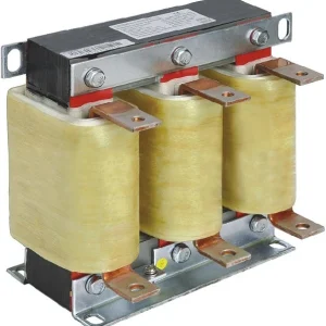
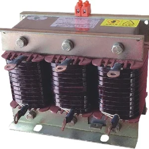
Measure the effective output of the step at the actual voltage. Capacitor output varies approximately with voltage squared at a fixed frequency and unchanged capacitance, and detuned branches require their own pairing calculations. Use the detuned-reactor guide when interpreting net step kvar rather than treating every nameplate label as the measured output.
Review the control band and each delay separately
A control band or hysteresis arrangement defines when a correction is needed and when the current state is acceptable. Its purpose differs from a time delay. A suitable band can prevent small changes or noise from repeatedly reversing a decision; a delay determines how long a condition must persist or how a sequence is permitted to proceed.
Identify the controller's actual definitions for connection delay, disconnection delay, reverse delay, minimum on/off times, reclosure blocking, and discharge-related restrictions. Do not assume similarly named settings have the same meaning in different products. Some controllers also base decisions on reactive deficit, PF zones, learned step values, or a combination of quantities.
Changing every delay to a large value can reduce the observed operation count while making the bank too slow to follow genuine demand. Reducing delays indiscriminately can violate component or discharge requirements. The correct adjustment must be supported by the controller manual, capacitor/switching requirements, and the measured load behavior.
For the switching-device distinction, use the thyristor versus contactor switching comparison. A faster device does not repair incorrect sensing or unsuitable step resolution, and it does not remove the need for a coherent control sequence.
Distinguish command problems from step and protection problems
A commanded step may fail to deliver the expected kvar because of switching failure, an unavailable branch, a protection action, a failed component, or an incorrect learned step value. The controller can then continue requesting correction that never appears. Check the relationship between command, feedback, branch current, and reactive-power change.
Review alarms and reset logic before treating a repeating sequence as harmless chatter. An overtemperature or overcurrent event followed by automatic recovery can produce regular reconnect attempts. Repeatedly clearing the alarm without investigating the original duty can obscure the evidence and leave the panel exposed to the same condition.
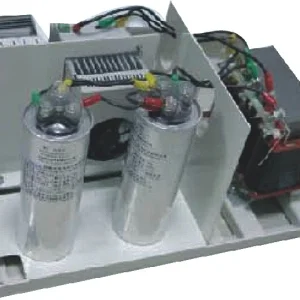
Voltage conditions, harmonics, capacitor degradation, and cooling issues need their own assessment. The scope of IEC 61921 covers low-voltage power-factor-correction banks, including assemblies with switching and control equipment. A controller setting does not replace verification of the complete bank's electrical and thermal suitability.
Use the actual controller documentation, not cabinet appearance
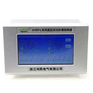
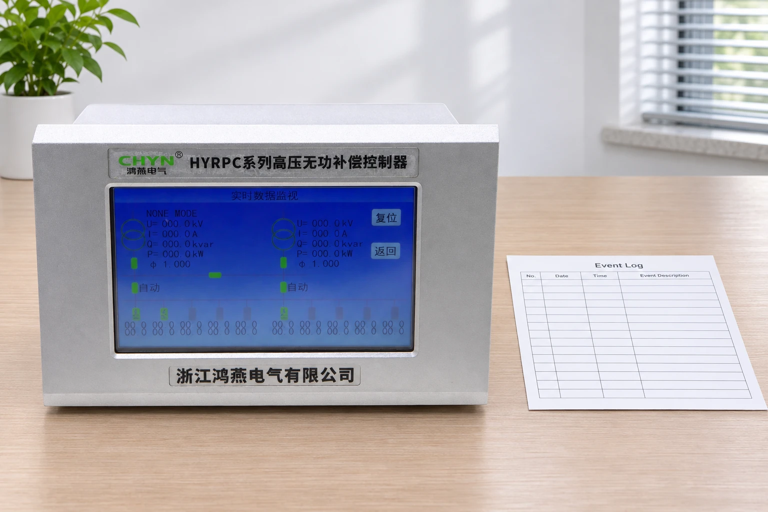
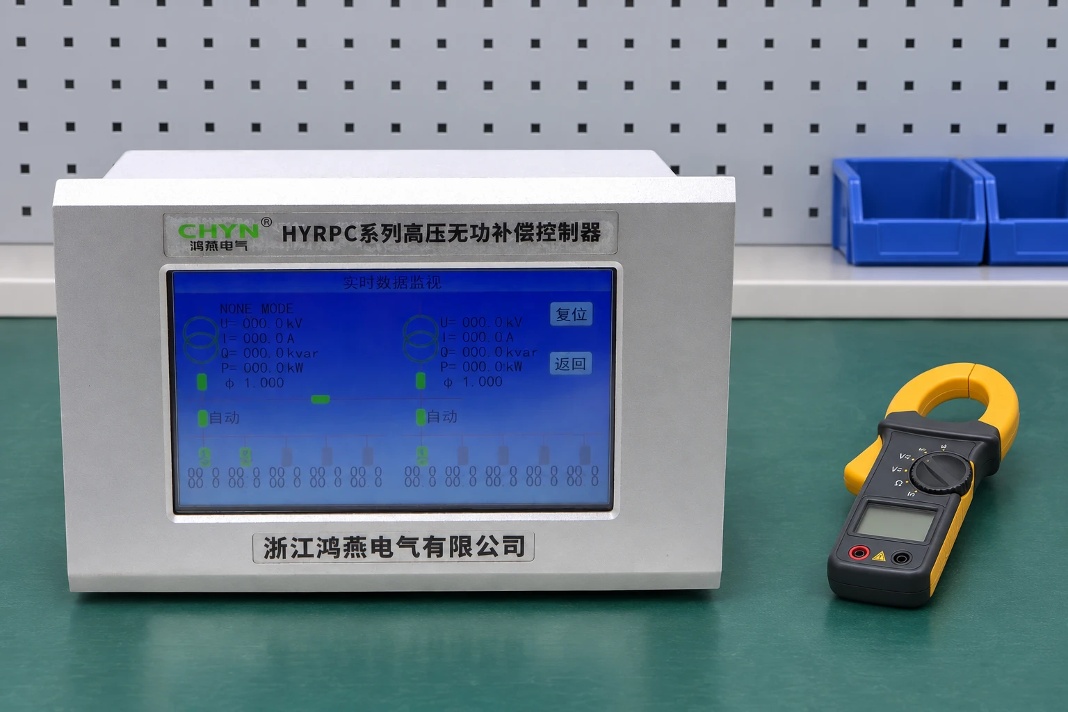
CHYN's HYRPC compensation-controller product page describes anti-oscillation logic, separate delay functions, operating records, and configurable control modes. Confirm which functions and definitions apply to the proposed or installed version before using them in a diagnosis.
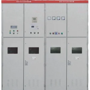
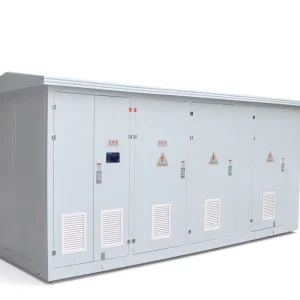
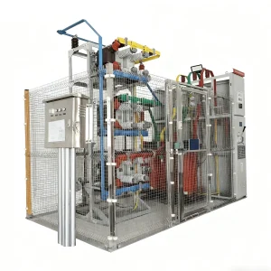
The illustrations use the existing HYRPC family controller photograph as product context. They do not represent a recommended setting, measured operating value, or confirmation of a particular panel's voltage class. Use the model-specific manual and approved wiring information to identify the actual application.
Verify the repair across the operating range
Define success before changing the system: appropriate correction, permitted operation count and switching duty, no unresolved alarms, and acceptable behavior at low and high load. Compare the before-and-after records under similar conditions. A quieter panel is not necessarily correctly compensated.
Include the operating states that previously triggered the behavior. Where solar production, alternative supply modes, or production changes affect the sensing boundary, test those relevant states as well. Retain the final settings, step measurements, event log, and explanation of the cause so later maintenance can distinguish a new fault from the original condition.
The APFC panel design guide provides the wider assembly context. Hunting diagnosis is a focused feedback and switching investigation, not a reason to replace the whole panel before its measurements and operating sequence have been understood.
Information to provide for technical review
- The one-line and control drawings, sensing locations, controller model/version, and original settings record.
- Time-aligned kW, kvar, voltage, PF definition, load state, step commands, actual feedback, and alarm sequence.
- Measured or approved step outputs, step combinations, switching devices, discharge arrangement, and permitted duty.
- Harmonic measurements, relevant thermal observations, and recent changes to loads, solar generation, or supply configuration.
- The proposed corrective action and an acceptance test covering the states that caused the repeated switching.
Further learning: reactive-power compensation
NPTEL IIT Guwahati's lecture “Lec 21: Reactive power compensation: Basic idea” explains why reactive support changes the electrical state seen by a controller. It supplies circuit background, not APFC commissioning values or a site-specific repair instruction.
Watch Lec 21: Reactive power compensation: Basic idea on YouTube.
Frequently asked questions
Is frequent APFC switching always hunting?
No. Legitimate load changes, step rotation, and repeated protection/reset events can also cause frequent operations. Establish the actual command, feedback, power-flow, and alarm sequence.
Can increasing the delay fix every hunting problem?
No. It may hide incorrect sensing, unsuitable step size, or a component fault and can make compensation too slow. Check the actual delay definitions and required component duty.
Why does hunting often appear at low load?
One available step may be too large relative to residual demand, while PF becomes more sensitive to small reactive changes. Measurement noise and minimum-load behavior also need checking.
What data should I send for technical review?
Provide the drawings, controller model and settings, time-aligned kW/kvar/voltage data, step commands and feedback, alarm history, measured step outputs, switching/discharge details, and recent system changes.