
 Zhejiang Hongyan Electric Co., Ltd.





































A power factor correction panel design freezes capacitor steps, detuned reactors, heat paths, and current-transformer placement in one low-voltage cabinet so the controller can track lagging load without hunting. Power factor is real power divided by apparent power; a lagging plant draws extra feeder current for the same useful work.
The rest of this page is the cubicle work: what to lock on the general-arrangement drawing, how an APFC panel is partitioned, when a detuned reactor changes the box, when Filter/Compensation Modules beat a packaged HYTBBJ, and where the APFC controller belongs. Kvar arithmetic and control-wire pinouts live on other CHYN pages.
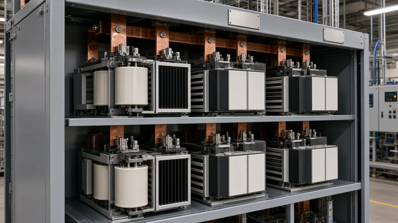
What a power factor correction panel has to freeze
A power factor correction panel is the enclosure whose capacitor steps, busbar, switching, protection, APFC controller, and heat path are specified together. It is not a loose pile of cans and not a one-line kvar target.
IEC 61921 covers low-voltage power factor correction banks, including automatically switched assemblies, and points to IEC 61439 assembly rules where they apply. Treat that pairing as the cubicle language for an APFC panel, not as a CHYN listing mark.
| Cubicle freeze | What it decides | Leave to another job |
|---|---|---|
| Step geometry and first-step size | Hunting vs night load | Worked kvar formulas |
| Detuned reactor yes/no and percent | Resonance and tray height | Relay terminal maps |
| CT and voltage at the corrected bus | What the APFC controller sees | Field landing torque lists |
| Heat path and ventilation | Capacitor life under harmonic current | Home-install sequences |
A capacitor-duty contactor (or a faster electronic switch) is part of that freeze because each capacitor step is a switched increment of correction. If the drawing only names total kvar, the panel shop still has to invent the cubicle.
Design sequence before anyone cuts sheet steel
Freeze load profile and harmonics, then the step plan, then detune and heat, then sensing — kvar math is a later input, not the cubicle. A transformer nameplate in kVA does not tell you night-time reactive demand or whether VFDs already sit on the bus.
Walk the order like a drawing checklist:
- Record max and min running kW and how fast motors and drives come and go.
- Note whether harmonic current is already a problem on that bus.
- Partition correction into capacitor steps the smallest of which can follow light load.
- Decide plain steps versus detuned reactors before you lock tray height.
- Place the current transformer and voltage take-off on the electrical point you intend to correct.
- Only then pick Filter/Compensation Modules or a packaged HYTBBJ cabinet.
A plant that sizes the box from connected load and then asks for “a 200 kvar APFC panel” often learns the hunting lesson after contactors ship.
How capacitor steps are laid out so the bank does not hunt
The smallest capacitor step must fit night-time reactive demand; do not aim the APFC controller at unity. Hunting is rapid on/off of contactors when the first step is larger than the leftover lagging vars.
Many plants keep a high lagging target rather than unity so a quiet shift cannot go leading. Binary 1-2-4 stacks and mixed 25/50 trays exist because they let the controller land between two noisy extremes.
Imagine a compressor room that drops to a few motors after midnight. A single 50 kvar first step on that bus will chatter; a smaller first tray plus larger follow-on trays tracks the same daytime peak without overnight leading power factor.
When detuned reactors change the cubicle, not just the BOM
Series reactors move resonance and add heat and height; they are a cubicle decision. A detuned reactor is the coil in series with each capacitor so VFD harmonics do not pile into the cans.
A plain capacitor step can sit on a harmonic resonance with VFD harmonics; that is a drawing input, not a wiring afterthought. When VFDs and rectifiers are a large share of the transformer, treat detune as the default step type.
Filter/Compensation Modules publish detuning options of 5.67%, 7%, 12% or 14%. Those percents change reactor bulk, capacitor voltage stress, and how much air the cubicle must move.
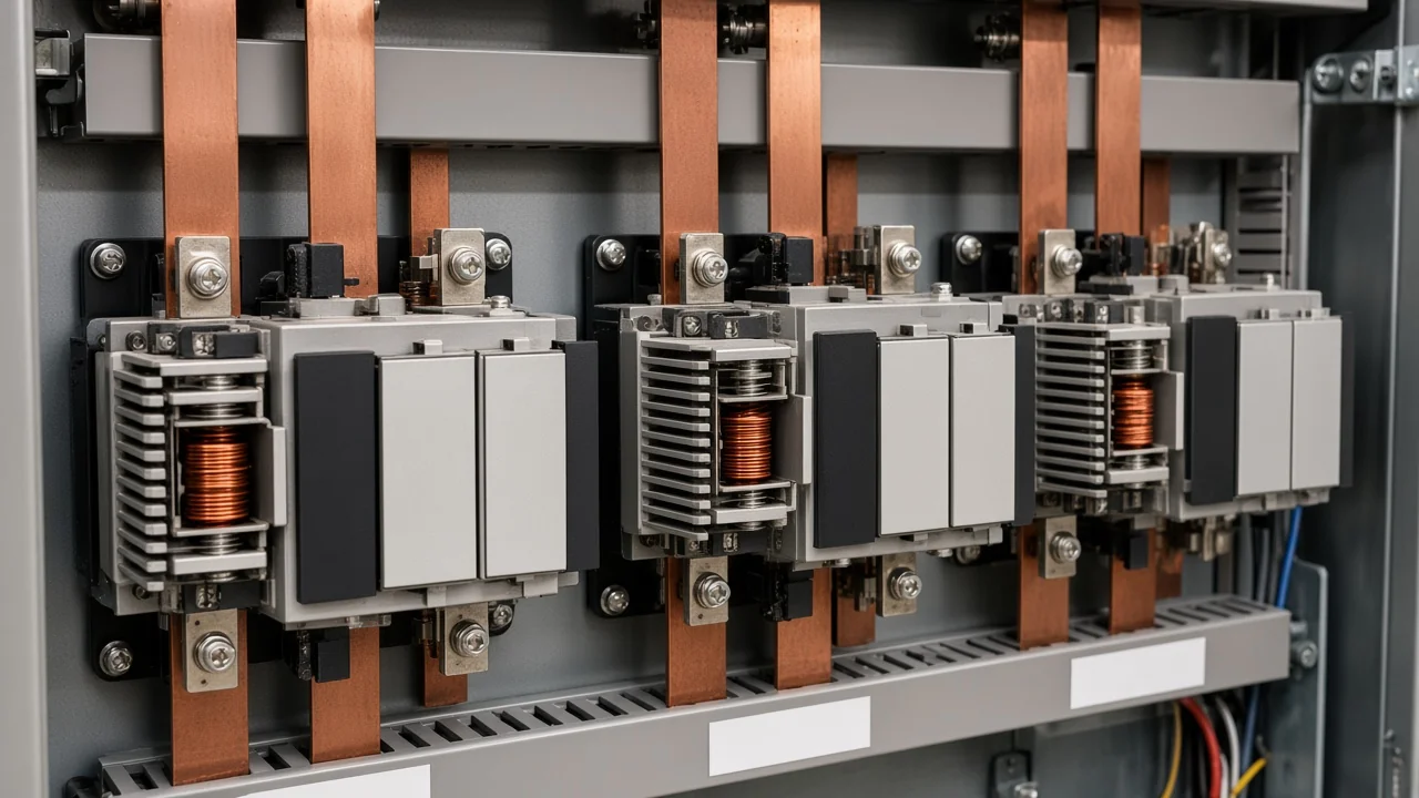
Module trays versus an assembled HYTBBJ enclosure
Modules are bolt-in detuned steps; HYTBBJ is the packaged static cabinet for steadier loads. Filter/Compensation Modules combine capacitors, detuned reactors, contactors, fuses, busbars, and terminals as compact trays for cabinet modularization.
HYTBBJ automatically switches capacitor groups by measured reactive demand or power factor. It is built for distribution with relatively steady inductive loads, with switching delay adjustable from 0 to 120 seconds and a fast mode of 1 second or less.
| Path | Use it when | Watch-out |
|---|---|---|
| Filter/Compensation Modules | A panel shop is filling or extending an LV cubicle and wants repeatable detuned trays | Standard-size fill limits on the module page |
| HYTBBJ assembled enclosure | The plant wants a floor-standing static cabinet rather than a shop build | Not the right deep pick for highly fluctuating loads (see the LV hub’s dynamic family) |
A shop expanding an existing 800 mm cubicle usually wants trays. A food plant that will never open the doors except for service usually wants the assembled HYTBBJ.
CT and controller choices that belong on the GA drawing
Put the current transformer and voltage at the electrical point you intend to correct, on matching phases. The APFC controller only switches capacitor steps from the V/I pair you give it.
The sensing CT belongs on the incoming of the bus you intend to correct, not only on a downstream MCC pocket. If the bank ties through a sub-MCC while the CT sits on the main incomer on a different phase than the PT, the controller can drive every step in.
From the field: Commissioning threads keep repeating the same miss: CT on one phase, controller voltage on another, and the bank piles in as if the plant were still fully lagging (Eng-Tips automatic capacitor bank CT location).
Leave coil-to-terminal maps to the control-wiring article. The design job is to show CT location, polarity convention, and controller door cut-out on the GA before the cubicle is welded.
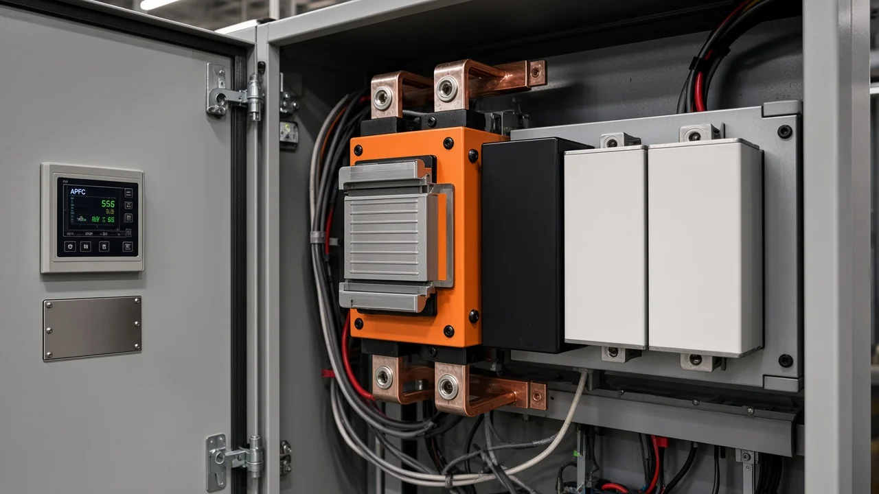
Heat, harmonic current, and what overloads the enclosure
Put reactors above capacitor cans and keep a barrier so heat does not pool on the capacitors. Harmonic current is an overload on fuses, contactors, and cans, not a footnote under “power quality.”
The modules list over-voltage, under-voltage, over-temperature, and harmonic overload protection. Those trips do not replace a cubicle that can actually reject reactor heat.
Detuned trays run warmer than plain capacitor steps. Leave chimney space, do not park reactors beside capacitor tops, and treat blocked louvers as a failure mode equal to a wrong CT.
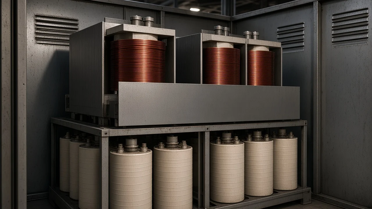
Filter/Compensation Modules as the product step you can buy
Use published module detune, voltage, and fill limits as the drawing’s step library. Filter/Compensation Modules are the CHYN trays built for that library.
Rated voltage options are 400, 450, 480, and 525 V. Capacitor capacity sectional range is 12.5–50 kvar per unit.
Ordering notes on that page: suitable cabinet width is at least 800 mm; each 50 kvar is one switching step; for 525 V systems the recommended detuning factor is 12.5%. Max installable capacity per standard-size cabinet is 50 kvar modules up to 250 kvar, or 25 kvar modules up to 225 kvar.
If the plant is not building a cubicle and the load is relatively steady, compare the HYTBBJ Series Low-Voltage Static Reactive Power Compensation System on the low-voltage power factor compensation series. Control wiring after the cabinet exists is covered in how to wire an APFC panel control circuit. Kvar math is covered in how to size a capacitor bank.
FAQ
What is a power factor correction panel in an LV switchroom?
It is the metal cubicle that holds switched capacitor steps, busbar, protection, ventilation, and the APFC controller that tracks lagging load. Automatic power factor correction is the function; the panel is the hardware that makes that function installable.
Why do APFC panels hunt and chatter contactors?
The first capacitor step is larger than light-load reactive demand, or the target sits too close to unity. The controller then adds and dumps the same tray as the vars wobble around one step.
Where should the controller CT be placed at design time?
On the incoming of the bus whose power factor you are paying for, with voltage taken at the same electrical point and the same phase convention. A CT on a downstream MCC only “sees” that pocket.
When does a panel need detuned reactors instead of plain capacitors?
When nonlinear loads such as VFDs, rectifiers, welders, or UPS already inject harmonic current on that bus. Plain cans can sit on a harmonic resonance; a detuned reactor pulls the series resonance below the lowest significant harmonic.
Module trays or a factory-assembled HYTBBJ cabinet?
Use Filter/Compensation Modules when a panel shop is filling or extending a cubicle. Use HYTBBJ when the plant wants a packaged static cabinet for relatively steady inductive loads.
Can I design the panel from transformer kVA alone?
No. Transformer kVA is a ceiling, not a load profile. Night-time vars, harmonic current, and how fast motors cycle all change the cubicle.
Do I still need a harmonic survey if I buy modules?
Yes if the bus already has drives or other nonlinear load. Modules include harmonic-overload protection, but the survey still decides detune percent and whether a plain step is even legal on that bus.
Is this the same as APFC control wiring?
No. This page freezes cubicle layout and sensing on the GA. The control-wiring article covers CT polarity, step outputs, and commissioning checks after the box exists.