
 Zhejiang Hongyan Electric Co., Ltd.





































Correct apfc panel control wiring places the load CT, controller supply, and step commands so an automatic power factor controller switches capacitor banks for the net plant load. Get those paths right—with discharge delay and interlocks—and the bank tracks reactive demand instead of fighting it. The sections below map the panel-level control chain, the mistakes that reverse or hunt steps, and the commissioning order to run before Automatic mode.
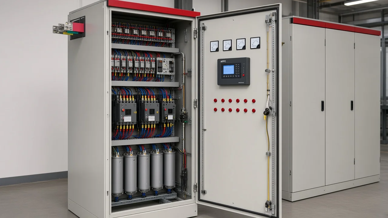
Related reading for definitions and bank selection stays separate: what is an automatic power factor controller and capacitor bank for power factor correction. Relay-terminal diagram reading belongs in its own sibling brief, not as a substitute for this panel wiring map.
What APFC Panel Control Wiring Actually Connects
It connects three jobs in one control circuit: measure the bus, decide compensation, and command each capacitor step.
On the power side, an incoming breaker feeds step protection (MCCB/MCB or fuses), then capacitor-duty contactors or thyristor modules, then the capacitor cans—often with detuned reactors when harmonics matter. On the control side, a protected control supply feeds the controller’s auxiliary/measurement inputs, while a load CT secondary lands on the controller current terminals.
Step commands leave the controller as potential-free contacts into Auto/Manual selectors or directly into contactor coils. Indication lamps, fan starters, and AUX interlocks share that control layer. Contractors who only ask for “the connections between the components” still need this split before any relay pin chart makes sense.
| Layer | Typical conductors | What they must do |
|---|---|---|
| Power | Bus → step protection → contactor/thyristor → capacitor | Carry bank current and inrush |
| Measurement | Bus voltage to controller; CT secondary to controller | Tell the controller real PF/kvar demand |
| Command | Control phase through COM/C1…Cn to coils or gates | Close or inhibit each step |
| Safety | Discharge path; AUX enable/trip; snubbers across coils | Limit residual voltage, EMI, and unwanted enable |
Place the Load CT Correctly and Keep Polarity Honest
Put the load CT upstream of the plant loads and upstream of the capacitor bank connection so the controller sees net current at the point of correction.
Do not hang the CT only on the capacitor feeder or only on one motor feeder if you intend to correct the whole service. Size the CT for expected loading with usable accuracy at light load, and match the secondary (1 A or 5 A) to the controller input you actually land.
Polarity matters. Markings such as H1 facing the source and X1 to the controller’s matching terminal keep the voltage and current phasors usable. Keep shorting links on until the secondary is landed; an open CT secondary can develop dangerous voltage.
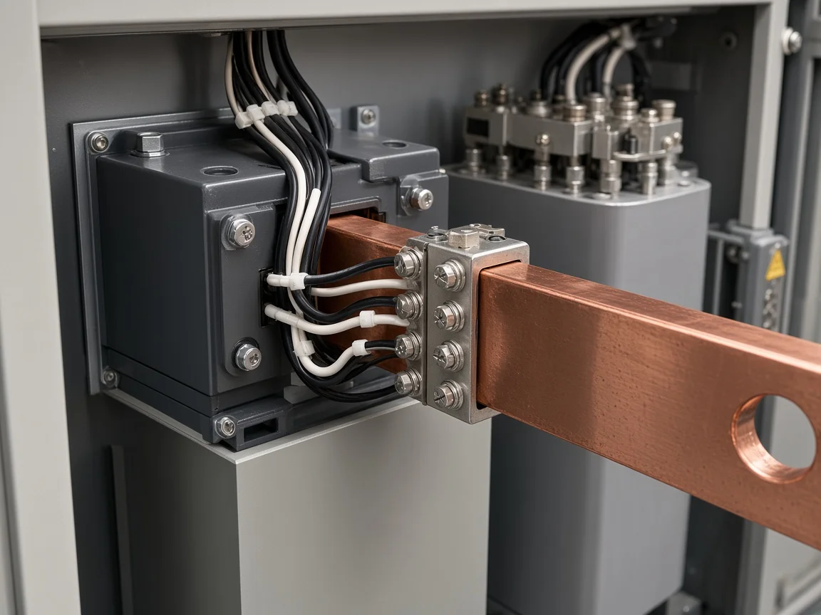
Important: Never leave a load-feedback CT secondary open during installation or maintenance. Keep shorting links installed until the controller terminals are complete — TCI PF Guard installation guidance.
After the short is removed, many controllers show signed kW. A negative reading with banks still off is a classic reversed-polarity flag. Correct the physical polarity, or use the manufacturer’s auto-synchronization only after you understand what it remaps.
Independent engineering notes also stress placing the CT at the service entrance ahead of loads and the bank, not on a partial feeder (Voltage Disturbance).
Feed Controller Supply and Measurement Voltage Cleanly
Feed measurement and contactor-coil circuits from a coherent phase plan so a voltage sag does not drop coils while the controller still thinks a step is closed.
Many panels take phase-to-phase measurement (for example R–Y) with the CT on the third phase, or phase-to-neutral measurement with the CT on the same phase. Follow the controller’s published combinations; guessing the compensation angle produces “wrong way” switching even when every screw is tight.
Bring controller auxiliary supply through its own control MCB. Keep wire numbers and ferrules consistent from the door device to the DIN terminals. Where OEM manuals warn about controller resets when contactor coils share the same supply phase without snubbers, separate the noisy coil feed or add suppression across every coil.
The same independent wiring note asks for contactor coil voltage and PF measurement voltage from the same phase to reduce drop-out and chatter during sags (Voltage Disturbance).
Wire Step Outputs to Contactors or Thyristor Modules
Controller step outputs usually close a coil circuit; they do not invent the coil’s power source.
Typical practice feeds a protected control phase into the controller COM terminal. Each Cn output then goes to the Auto side of a selector or straight to contactor A1, with A2 returned to neutral for 230/240 V AC coils.
The contacts are potential-free N.O. points sized for the inductive coil load. Treat them as signaling contacts with proper fusing—not as a random power tap.
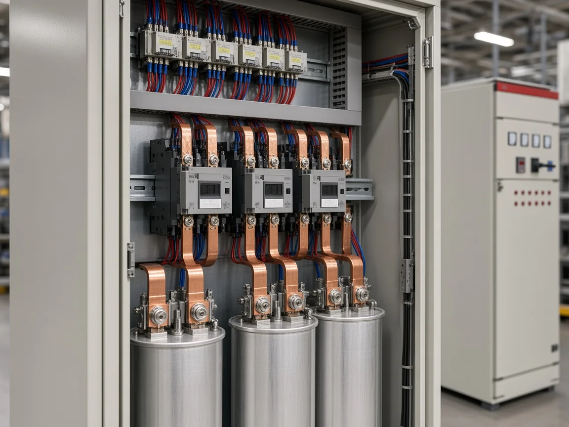
Auto/Manual selectors let the same contactor coil accept either the controller command or local pushbuttons. That is how maintenance proves a step without trusting Automatic mode first.
Use capacitor-duty contactors (often described as AC-6b class) on electromechanical banks. A thyristor switch or other solid-state step module follows the same command idea but needs its own gate-supply and zero-crossing notes from the module maker—do not paste contactor coil rules onto SCR firing boards.
Fit an RC snubber or MOV across each AC contactor coil. Coil collapse spikes are a frequent reason controllers reset or age their output relays early.
Set Discharge Delays, Interlocks, and Protection Paths
Enforce a real OFF-to-ON delay so a step cannot reclose while residual voltage is still high, and wire external enables so the bank cannot compensate into the wrong source condition.
Educational summaries of IEC 60831-1 describe LV self-healing capacitors discharging toward a low residual voltage within a few minutes; independent notes also describe APFC practice that waits until residual voltage is a small fraction of rated before re-energizing (discharge methods overview, IEC 60831-1 abstract). Set the controller reconnection delay to match the capacitor’s discharge design—not the shortest menu value that “feels responsive.”
Use AUX or enable inputs for master trip, PLC permission, or generator/utility changeover. Multi-source and solar-export sites are where ordinary PF logic hunts if it never sees reverse active power. Interlocks do not replace harmonic assessment, but they stop the control circuit from enabling a bank when the plant topology is wrong.
Step protection (fuses/MCCBs), over/under-voltage trips, and fan or temperature contacts belong in the same commissioning pack as the CT leads. Leave invented terminal numbers out of drawings unless the live controller manual shows them.
Fix the Control-Wiring Mistakes That Reverse or Hunt Steps
Most “bad APFC behavior” starts as a wiring or timing error, not a mysterious algorithm.
Wrong CT location makes the controller correct only a feeder or ignore the bank contribution. Reversed polarity or mismatched V/I phase pairs drive steps the wrong way.
An open or loose CT secondary is both a safety hazard and a noise source. Missing snubbers let coil spikes reset the door device. Zero discharge delay reconnects a charged can and multiplies inrush.
Field discussions also report frequent switching and hunting when harmonics and rooftop solar confuse an ordinary relay (r/powerquality thread). That is a topology and relay-capability issue as much as a screw-tightness issue: detuned banks, dynamic compensation, or four-quadrant control may be required instead of retightening Cn.
Genset-plus-solar threads ask whether a large APFC belongs on a swinging islanded bus at all (r/dieselgenerators). Wire the inhibit first; argue kVAr sizing second.
Commission the Control Circuit Before Automatic Mode
Prove the control circuit with capacitor bank protection still open, then unlock Automatic mode only after Manual step checks pass.
| Step | Action | Pass look |
|---|---|---|
| 1 | Torque check power and control landings; confirm drawing vs panel | No loose CT secondary; labels match |
| 2 | Keep bank MCBs/fuses open; energize controller only | Display boots; no bank current |
| 3 | Remove CT short; check signed kW/PF with plant load | Polarity sane; not stuck negative |
| 4 | Manual mode: close each contactor or thyristor enable | Correct step device operates |
| 5 | Confirm snubbers/MOVs and Auto/Manual selectors | No controller reset on coil drop-out |
| 6 | Set target PF, step sizes, discharge/reclose delay | Delay matches capacitor discharge design |
| 7 | Close bank protection; Automatic mode under watched load | Steps track demand without hunting |
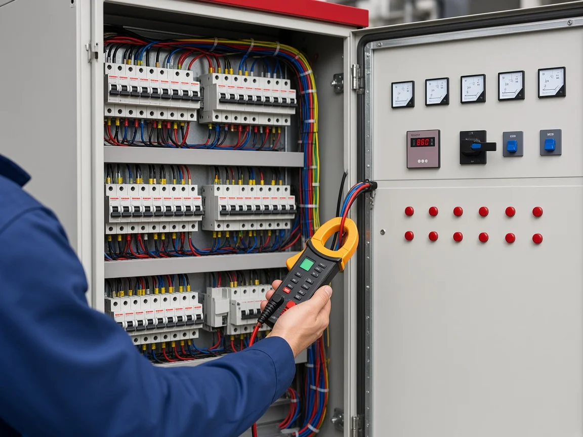
If Automatic mode immediately chatters, return to CT placement and discharge delay before changing target PF. A clean Manual prove-out with banks isolated is the cheapest insurance on a new panel.
Choose a Static APFC Panel When the Load Is Steady
Choose a static stepped APFC assembly when the inductive demand is relatively steady and the control wiring above is enough to keep PF on target.
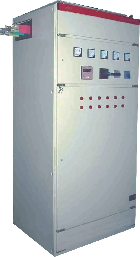
The HYTBBJ Series Low-Voltage Static Reactive Power Compensation System automatically switches capacitor groups by measured reactive demand or power factor. The live product page lists manual and automatic modes, real-time monitoring of three-phase voltage, current, power factor, and compensation status, an adjustable capacitor switching delay of 0–120 s, a special fast mode ≤1 s, and protections covering over-voltage, under-voltage, over-current, short circuit, capacitor fault, and switching error.
That feature set matches a plant where motors and building loads move slowly enough for contactor or staged switching. It is a poor default when load swings are violent, harmonics trap plain capacitors, or bidirectional solar/genset power needs four-quadrant logic—compare dynamic options on the low-voltage power factor compensation series hub instead.
For project scope, start from the HYTBBJ page parameters and the control map above, then send the measured load profile with the enquiry rather than a blank “need APFC” note.
FAQ
Where should the CT sit for APFC panel control wiring?
Place the load CT on the incoming path ahead of plant loads and ahead of the capacitor bank connection so the controller measures net current at the correction point.
Why does reversed CT polarity confuse the controller?
Reversed polarity flips the current phasor relative to voltage, so the controller may add capacitors when it should remove them. Negative kW with banks off is a common field clue.
Do controller outputs power the contactor coils directly?
No. Outputs are usually potential-free contacts that close a separately supplied coil circuit. COM still needs a proper control-phase feed.
How long should discharge delay last before reconnecting a step?
Long enough for the capacitor’s discharge design to bring residual voltage down. Independent discharge guidance and LV capacitor standards both warn against instant reclose on a charged step.
Why add RC snubbers or MOVs across contactor coils?
Coil collapse creates voltage spikes that can reset controllers or wear output relays. Suppression across each AC coil is standard panel practice.
Which interlocks belong in the APFC control circuit?
At minimum, master trip or enable contacts for unsafe topology—generator/utility changeover, PLC permission, or solar-export conditions that ordinary PF logic cannot interpret.
How do Auto and Manual paths share one contactor coil?
A selector routes either the controller Cn output or local pushbuttons to the same coil A1 path so maintenance can prove a step without Automatic mode.
What commissioning order keeps capacitor banks safe?
Energize and parameterize the controller with bank protection open, prove each step in Manual, set discharge delay, then close bank protection and watch Automatic mode.
References
- How to wire a power factor controller — Voltage Disturbance (independent technical)
- Capacitor bank discharge methods — Voltage Disturbance (independent technical)
- IEC webstore abstract for LV self-healing shunt capacitors — IEC (standards body)
- APFC customization and installation questions — r/ElectricalEngineering (community forum)
- APFC hunting and solar interaction discussion — r/powerquality (community forum)