
 Zhejiang Hongyan Electric Co., Ltd.





































The direct answer to what is automatic power factor controller is an automatic control unit that measures system power factor and switches capacitor steps so the plant stays near a chosen target as inductive loads change. The sections below cover sensing, the switching loop, a block-diagram view of the parts, contactor versus thyristor contexts, how “relay / panel / bank” names differ, and when a static low-voltage system such as HYTBBJ is the right class of equipment.
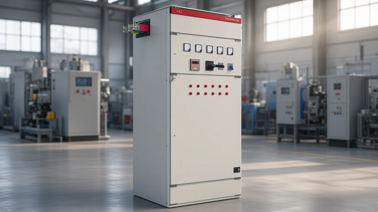
What an Automatic Power Factor Controller Is
An automatic power factor controller is the automatic “brain” that keeps power factor near a set target by connecting and disconnecting capacitor steps.
Power factor is the ratio of real power (kW) that does useful work to apparent power (kVA) drawn from the supply. Many industrial loads—motors, compressors, welders, HVAC—are inductive.
They pull reactive power as well as real power, so power factor falls and the feeder carries more current for the same useful work. Capacitors supply that reactive power locally. An APFC does not ask an operator to guess which bank to close; it measures conditions and commands the steps.
People use several related names. “Automatic power factor controller” or “APFC relay” usually means the measuring and decision device. “APFC panel” usually means the assembled cabinet that also holds capacitor banks, switching devices, and protection.
The capacitor bank is the kVAR source the controller turns on and off. Keeping those three roles separate makes later selection conversations clearer.
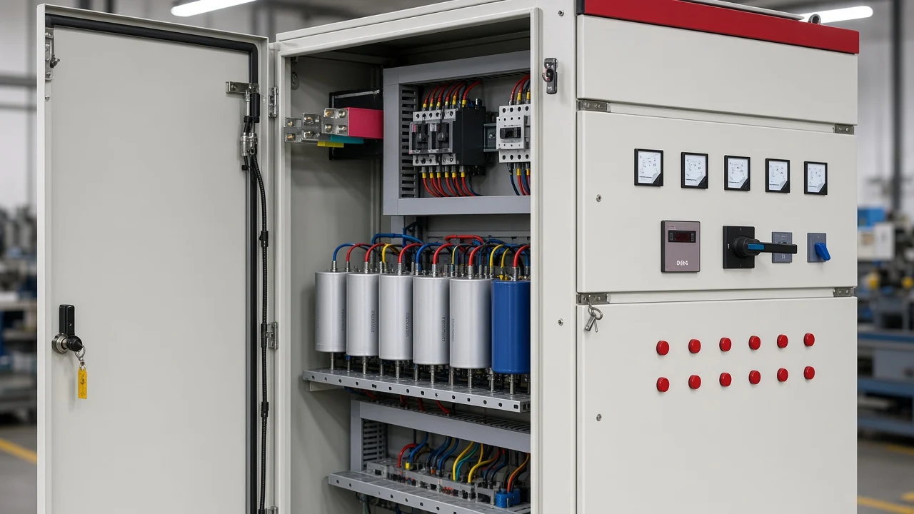
How an APFC Senses Voltage, Current, and Power Factor
The controller senses voltage and current—often through a current transformer (CT)—and derives power factor from their phase relationship.
In a typical low-voltage arrangement, voltage inputs come from the monitored bus, and CTs scale load current down to a safe measurement level for the relay. From those waveforms the controller finds the phase difference between voltage and current, then expresses power factor and the reactive power that still needs correction.
Some designs also display related quantities such as voltage, current, and step status so operators can see why a step moved.
Sensing quality matters as much as the switching hardware. CT polarity and placement must represent the load the capacitors are meant to correct. If the measurement point and the capacitor connection point tell different stories, the relay can chase the wrong reactive demand.
Controllers that rely on current magnitude also need enough signal. Under very light load, current can fall toward levels where PF calculation becomes unreliable, which is one reason plants sometimes combine fixed banks with automatic steps rather than expecting the relay alone to manage every operating hour.
Target Power Factor and Capacitor Step Switching
The controller compares measured power factor to a target band and connects or drops capacitor steps until the band is met.
| Step | What happens | Why it matters |
|---|---|---|
| 1. Measure | Read voltage/current and compute PF / reactive need | Establishes the present lag or lead |
| 2. Compare | Check measured PF against the programmed target | Defines whether more or less kVAR is required |
| 3. Decide | Select which capacitor step(s) to add or remove | Matches correction to step sizes available |
| 4. Switch | Close or open contactors / thyristor modules | Applies or removes reactive power |
| 5. Re-check | Confirm PF after the delay window | Prevents hunting and overcompensation |
Published technical pages often discuss target settings in the high-0.9s (for example around 0.95–0.99). The exact number is a site decision: utility tariff rules, transformer loading goals, and how close the plant wants to run to unity without tipping into a leading power factor.
The controller’s job is to hold that chosen band automatically as motors start and stop.
When measured PF falls below the target, the relay adds capacitive kVAR. When PF rises past the band—or reactive demand falls—the relay drops steps so the plant does not sit overcompensated.
Time delays between switching events keep the panel from “hunting” on every short load blip. That loop—measure, compare, switch, wait, measure again—is the power factor controller working principle behind almost every APFC explanation in engineering education and field practice.
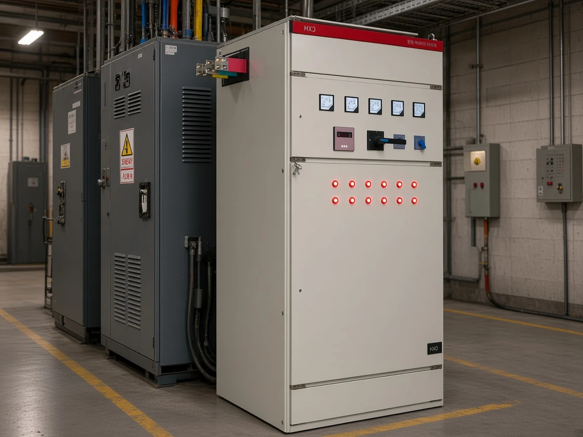
Block Diagram Narrative: From Sensors to Capacitor Banks
Sensors feed a controller that commands switching devices into capacitor banks, with protection wrapped around each step.
Think of the signal path as a short chain. Voltage and current sensors sit at the front. The controller (microcontroller or dedicated PF relay) sits in the middle, running the target comparison and step logic.
Switching devices—contactors or thyristor modules—sit between the supply and each capacitor group. The capacitor banks themselves are usually arranged as several steps so correction can be added in pieces rather than as one large block.
Protection devices (fuses, breakers, and related trip logic) guard against short circuits, abnormal voltage, and capacitor faults. A display or indicator set shows PF and which steps are in service.
That narrative is enough for most buyer and engineer conversations. A full wiring drawing belongs in project documentation; the block story answers what each part is for and how information moves from the CT to the capacitor terminals.
Contactor Switching vs Thyristor Switching
Contactors fit slower reactive changes; thyristor modules fit rapid swings and switching that must limit capacitor inrush.
| Switching approach | Typical load behavior | Practical note |
|---|---|---|
| Capacitor-duty contactors | Reactive demand changes over seconds | Common electromechanical APFC steps; use proper capacitor-duty practice |
| Thyristor switching modules | Fast, repetitive reactive swings | Used when loads change quickly; can be timed near zero voltage to limit inrush |
Industrial reference designs describe contactor-based steps for mid-to-low voltage automatic correction when the reactive need moves slowly enough for electromechanical switching. They reserve thyristor switching modules for applications such as presses, cranes, lifts, spot welding, or extrusion, where reactive demand jumps and inrush control matters.
Capacitor-duty contactors often use auxiliary pre-insert paths so the main contacts do not close into a fully discharged bank at a voltage peak. Controllers also expect capacitors to discharge before reconnecting.
Important: Energizing a discharged capacitor at the wrong instant can create a sharp inrush and arc stress on contacts. That is why step delays, capacitor-duty switching hardware, and discharge practice belong in the same conversation as automatic PF control — source: Texas Instruments TIDUB67A and Engineering Stack Exchange capacitor-switching discussion.
None of this is a scorecard of advantages and disadvantages for procurement theater. It is a matching rule: choose the switching physics that matches how fast your reactive demand moves.
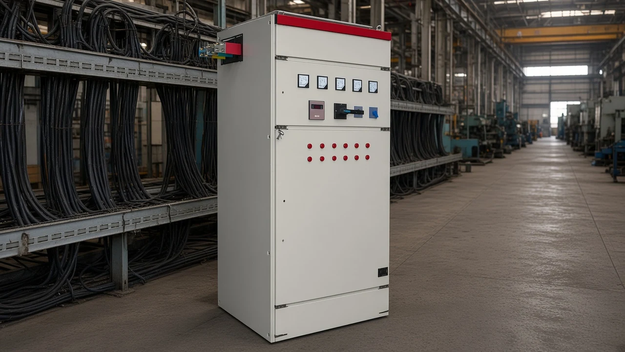
APFC Relay, APFC Panel, and Capacitor Bank Roles
The relay decides; the panel integrates; the banks supply kVAR.
| Role | What it is | What it does in the loop |
|---|---|---|
| APFC relay / controller | Measuring and decision device | Computes PF, compares to target, commands step outputs |
| APFC panel | Assembled enclosure | Houses relay, banks, switches, protection, indications |
| Capacitor bank / steps | Reactive power source | Injects or removes kVAR when switched |
Confusing the three names leads to incomplete scopes. Ordering “a controller” without sized steps leaves nothing to switch. Ordering “capacitors” without a controller leaves a manual bank.
Ordering “a panel” without stating target PF, CT arrangements, and switching type leaves the integration work undefined. For cluster navigation on CHYN, the low-voltage power factor compensation family sits under the low-voltage power factor compensation series hub.
When a Static LV System Like HYTBBJ Fits
HYTBBJ fits relatively steady inductive demand; dynamic cases need a different class of equipment.
After the sensing and switching loop is clear, the remaining decision is whether the plant’s reactive demand is stable enough for a static, step-switched low-voltage system. CHYN’s HYTBBJ Series low-voltage static reactive power compensation system is described on its product page as automatically switching capacitor groups according to measured reactive demand or power factor. It is aimed at distribution systems with relatively steady inductive loads in manufacturing, buildings, and public facilities, helping reduce reactive current, improve transformer utilization, and maintain the required power factor.
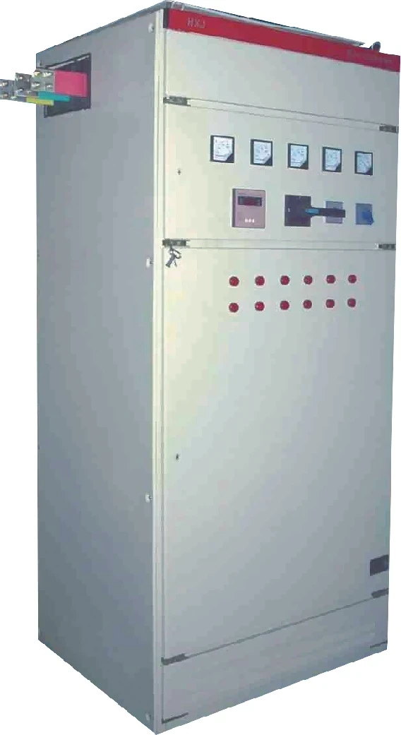
Live HYTBBJ features that matter for this definition article include power-factor / reactive-current control with manual and automatic modes; loop, group, and sequential switching options; and real-time monitoring of three-phase voltage, current, power factor, and compensation status.
The product page lists an adjustable capacitor switching delay from 0 to 120 seconds with a special fast mode within about one second, plus protection functions covering over-voltage, under-voltage, over-current, short circuit, capacitor fault, and switching error.
The page also states a typical harmonic current reduction of 20%–30% as a product claim for that series—not a universal industry guarantee.
When inductive load varies strongly—metallurgy, machinery, mining, building materials, petrochemical, municipal, and similar fluctuating distribution cases—the live HYTBBD Series dynamic product is the first-party contrast to evaluate instead of stretching a static design. That is a class match, not a feature invention: use HYTBBJ wording only where the page supports steady demand, and HYTBBD wording only where the page supports large variation.
FAQ
What is an automatic power factor controller?
It is the automatic control device that measures power factor and switches capacitor steps to hold a programmed target as inductive loads change.
How does an APFC sense power factor?
It takes voltage and current inputs—commonly with CTs on the load—and derives power factor from the phase relationship between those signals.
What is a target power factor on an APFC?
It is the PF band the controller tries to hold. Technical articles often discuss settings in the high-0.9s; the exact value follows utility and plant requirements.
How do capacitor steps switch?
When measured PF is too low, the controller adds steps; when PF is high enough or load falls, it removes steps after a delay so the system does not hunt or overcompensate.
What is the difference between an APFC relay and an APFC panel?
The relay is the decision device. The panel is the assembled cabinet that typically includes the relay, capacitor banks, switching devices, and protection.
When are contactors used instead of thyristor switches?
Contactors are common when reactive demand changes relatively slowly. Thyristor modules are used when loads change quickly and switching must limit capacitor inrush.
Why can capacitor switching stress equipment?
Closing into a discharged capacitor at a voltage peak can create a large inrush. Capacitor-duty switching practice, discharge time, and controller delays exist to reduce that stress.
When does a static system like HYTBBJ fit?
When reactive demand is relatively steady and a low-voltage static step-switched compensation system matches the plant profile, as described on the HYTBBJ product page. Strongly fluctuating inductive loads point to dynamic equipment classes such as HYTBBD.