
 Zhejiang Hongyan Electric Co., Ltd.





































An automatic power factor controller advantages disadvantages decision is really a plant-fit question: stepped APFC shines when reactive demand moves with the load, and it disappoints when cost, contactor wear, switching stress, or harmonics outweigh that flexibility. This guide weighs practical APFC panel advantages and APFC disadvantages against fixed capacitor banks, maps common LV industrial scenarios, and shows when Dynamic reactive compensation or SVG-class gear is the better next step.
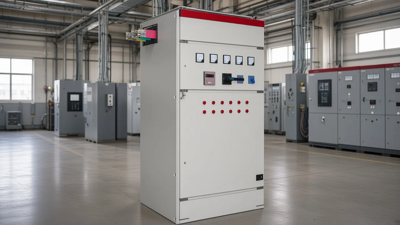
Practical advantages of an APFC panel in LV plants
APFC shines when it keeps power factor on target as loads change, cutting reactive current drawn from the supply and reducing exposure to low-PF charges where the utility applies them.
A low power factor means more current for the same useful kilowatts. That extra current heats cables and transformers and can raise industrial or commercial supply costs.
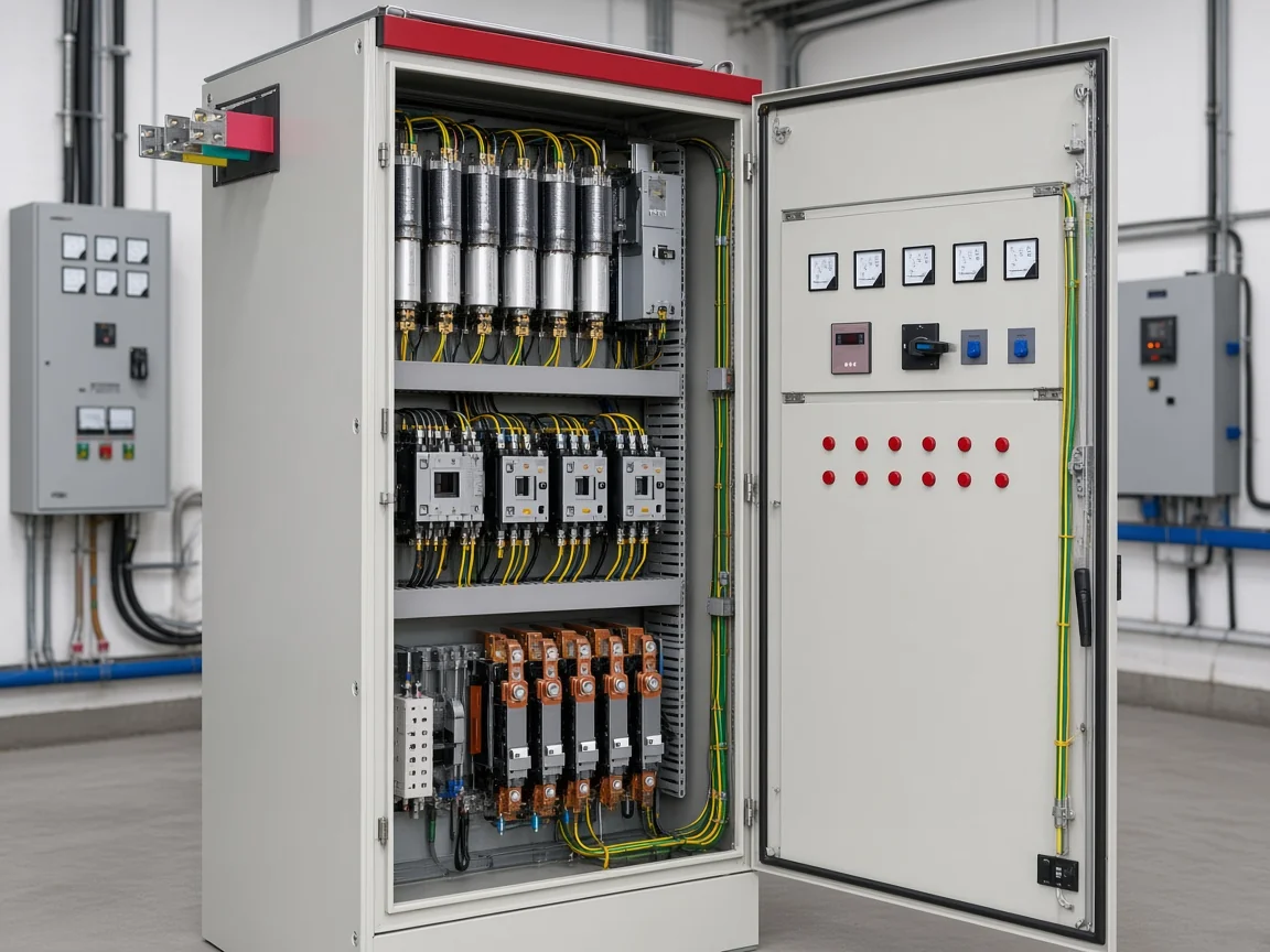
An automatic power factor controller watches measured PF or reactive demand and switches Capacitor bank / steps so compensation rises and falls with the plant instead of sitting at one fixed kvar value. That automatic tracking is the core of APFC panel advantages on multi-shift sites.
| Advantage | What it means on the plant floor |
|---|---|
| Tracks changing kvar | Multi-shift motors, conveyors, and process lines no longer rely on a single permanently connected bank |
| Lower reactive current | Upstream amps fall for the same real load when PF improves |
| Capacity headroom | Transformers and feeders free usable kVA without an immediate upsizing project |
| Local voltage support | Reactive support near the load reduces voltage drop on reactance-heavy feeders |
| Less manual switching | Operators do not retune capacitor breakers every time the production mix changes |
Those upsides explain the search for APFC panel advantages. They also explain why a fixed bank can look cheaper on day one and still leave night-shift loads overcorrected.
For background on what the capacitor steps themselves do once connected, see CHYN’s notes on what capacitor banks do and what capacitor banks are.
Practical disadvantages: cost, wear, and switching stress
You pay more up front for an APFC panel and inherit contactors, a controller, step timing, and maintenance points that a simple fixed bank avoids. Those APFC disadvantages matter as much as the benefits list on a brochure.
Stepped compensation is electromechanical work. Each time a step closes, the bank can draw a short high-frequency Switching transient / inrush.
Education material commonly describes that inrush as many times rated current, often on the order of about 10 to 20 times depending on network impedance and switching angle. Contactor tips wear. Relays need sensible target PF, step size, and reconnect delay.
If those settings are wrong, the panel hunts: steps chatter on and off, cables warm, and operators lose trust in the system.
| Disadvantage | Practical implication |
|---|---|
| Higher first cost | Controller, CT/VT sensing, multi-step contactors, and cabinet packaging cost more than a fixed bank |
| More maintenance points | Contactors, fuses, capacitors, and the relay all need periodic checks |
| Switching stress | Inrush and voltage transients stress contacts and nearby equipment |
| Harmonic sensitivity | Bare capacitors can amplify harmonics from VFDs and other nonlinear loads |
| Setting risk | Bad step size or delay produces hunting, undercorrection, or sustained leading PF |
From the field: Plant electricians on technical forums warn that excess capacitance—leading power factor—can cause large inrush currents during switching events and can show up as voltage flicker or accelerated wear on switches and contactors. That is not a reason to abandon APFC; it is a reason to size steps and discharge timing carefully and to avoid “more kvar is always better.” (Physics Forums thread on power-factor-correction capacitor banks)
APFC vs fixed capacitor banks: which tradeoff fits?
Fixed banks win when kvar demand is stable; APFC wins when light-load overcorrection or undercorrection is the real problem. The fixed vs automatic power factor correction choice should follow the load profile, not the brochure with the longer advantages list.
Industrial education guides describe fixed banks as constant kvar sources—simple and economical for steady loads. They also warn that fixed banks overcorrect when the plant runs light, pushing power factor leading and raising terminal voltage.
Automatic systems use a PF relay to switch multi-step banks (commonly described as several to about a dozen steps) so compensation follows the load.
| Decision factor | Fixed capacitor bank | Stepped APFC panel | Dynamic LV / SVG-class |
|---|---|---|---|
| Load profile | Near-constant inductive kvar | Moderate day/night or shift swings | Large or very fast inductive swings |
| First cost | Lowest | Medium | Highest |
| Overcorrection risk at light load | High if oversized | Lower when steps and delays are set well | Lowest for continuous control |
| Switching stress | Rare or none | Present on every step change | Device-class dependent; often smoother than contactors |
| Harmonic care | Still required | Still required; detune when needed | Often paired with broader PQ strategy |
If the site is a pump house with one duty point for most of the year, a carefully sized fixed bank—or end-point compensation near the motor—may be enough. If three production lines start and stop through the day, fixed kvar that looked perfect at noon can look wrong at midnight.
Overcorrecting individual motors with fixed caps has a sharper failure mode. Community technical threads document resonant circulating currents when an overcorrected motor coasts down and its generated frequency sweeps through the LC resonance. That risk is another reason plants move from bolt-on motor caps to coordinated bus-level APFC with sensible targets.
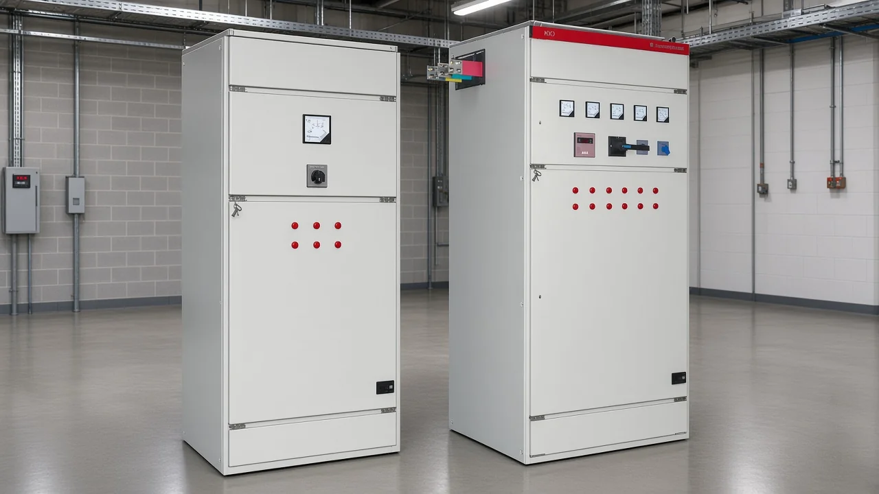
For sizing math and bank architecture detail outside this tradeoff page, use the published capacitor bank for power factor correction guide.
LV industrial scenarios where APFC usually pays off
Multi-shift motor plants and mixed inductive loads with moderate swings are the classic fit for stepped APFC.
Think of a food plant where conveyors, chillers, and packaging motors cycle through the day; a ceramics or cement auxiliary area where fans and mills change duty; or a commercial building with elevators and HVAC that do not share one steady kvar profile. In those rooms, automatic step switching is the practical answer to keeping PF healthy without babysitting breakers.
Typical plant signals that APFC is worth evaluating:
- Utility bills or contractual PF limits show chronic lagging PF during peak production
- Night or weekend readings show leading PF or voltage rise when a fixed bank stays online
- Operators already switch capacitor breakers manually by shift
- The transformer is near kVA limits even though kW headroom still exists
A brief note on the common PAA question “is 0.8 good?”: 0.8 lagging is a frequent industrial starting point, not a universal success target. Many projects aim closer to a solid lagging band near 0.95, but the right number is the one your tariff, generator, and voltage constraints allow—not a slogan of unity PF at any cost.
When APFC is the wrong tool: harmonics, hunting, and fast swings
Drive-heavy harmonics, chronic hunting, or very fast reactive swings need a Detuned reactor / harmonics strategy, Dynamic reactive compensation, or Static VAR generator / SVC class gear—not a larger classic APFC cabinet alone.
Capacitor banks and supply inductance form a resonant circuit. If that resonance lands near a strong harmonic (often discussed around the 5th), harmonic currents amplify and capacitors overheat.
Industrial guides therefore treat a harmonic survey as part of PF correction design. They use detuned reactors to shift resonance when nonlinear load share is significant.
Tip: If VFDs, welders, or other nonlinear loads are a large part of the plant, do not treat a plain contactor APFC as a harmonic filter. Detuned steps, passive filters, or active solutions belong in the same conversation as power factor — source: ElecCalc industrial PFC guide.
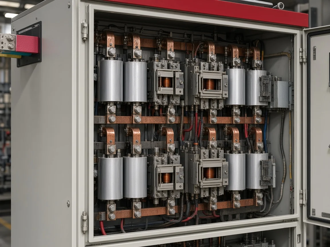
Hunting is another wrong-tool signal. Ordinary relays can struggle when reactive power direction flips (for example with bidirectional solar export) or when step size is too coarse for a lively load. Field reports from power-quality communities describe repeated capacitor failures and overheated cables when an undetuned APFC hunts through start/stop cycles.
When the issue is speed—large inductive swings that need near-continuous reactive support—converter-based static VAR equipment (SVG/SVC class) is the usual next class beyond stepped capacitors. Wikipedia’s Static VAR compensator framing is the same idea at system level: power-electronics VAR sources for fast reactive and voltage support. On the LV product side, a dynamic capacitor-switching package can sit between classic APFC and full SVG when fluctuation is the main problem.
Choosing an LV compensation path: HYTBBJ and when HYTBBD fits
HYTBBJ covers relatively steady inductive loads with automatic capacitor-group switching; HYTBBD is the live-page option when inductive load variation is large.
CHYN’s Low Voltage Power Factor Compensation Series—the LV Power Factor Compensation Series hub—groups static, dynamic, outdoor, and end-point packages for staged PF control in industrial and commercial networks.
The primary match for this advantages/disadvantages decision is the HYTBBJ Series Low-Voltage Static Reactive Power Compensation System.
The live page describes a system that automatically switches capacitor groups according to measured reactive demand or power factor, aimed at distribution systems with relatively steady inductive loads in manufacturing, buildings, and public facilities.
It supports power-factor (reactive-current) control with manual and automatic modes, multiple switching logics (loop, group, sequential), and real-time monitoring of three-phase voltage, current, power factor, and compensation status.
It also lists adjustable switching delay from 0 to 120 seconds with a special fast mode at or below 1 second, plus protections for over-voltage, under-voltage, over-current, short circuit, capacitor fault, and switching error.
The page also states a typical 20%–30% harmonic current reduction claim for the product feature set. Treat that as a model-page statement, not a substitute for a site harmonic study.
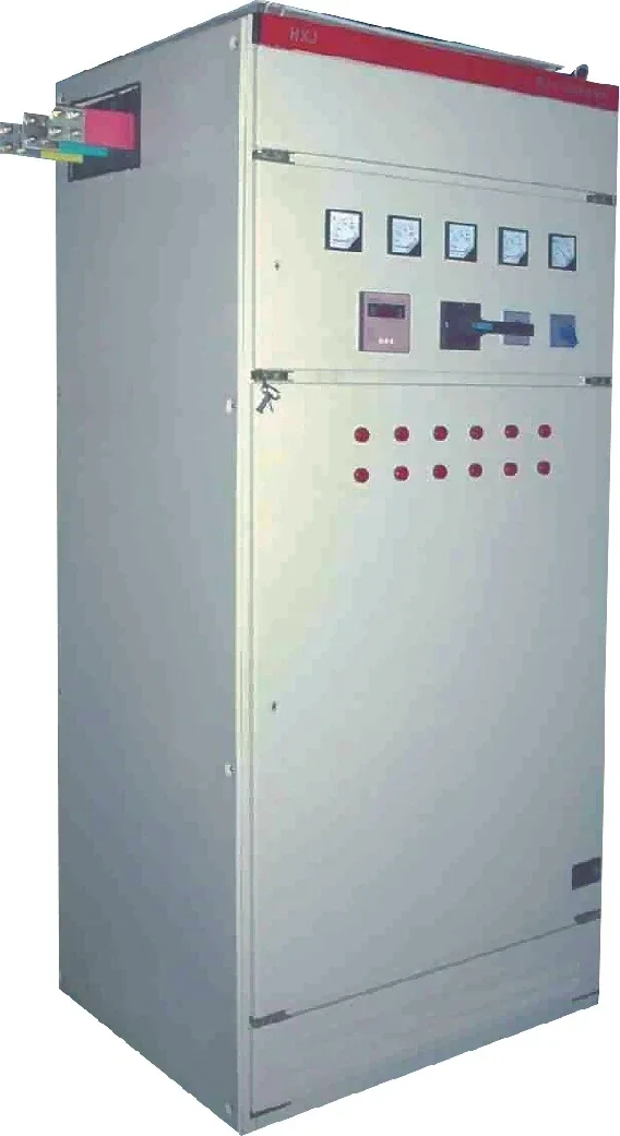
If the plant’s problem is strong load fluctuation—metallurgy, machinery, mining, building materials, petrochemical, or municipal distribution with large inductive swings—the live HYTBBD Series Low-Voltage Dynamic Reactive Power Compensation System page is the secondary path for Dynamic reactive compensation.
It states real-time reactive compensation, a target power factor of at least 0.95, and rated capacity per group of 15–60 kvar with dynamic switching. It also describes smoother switching logic aimed at reducing shocks during compensation.
Bring voltage level, measured PF profile, transformer rating, harmonic notes, and whether the load is “relatively steady” or “strongly fluctuating” to any enquiry. That information decides between fixed, HYTBBJ-style static automatic switching, HYTBBD-style dynamic switching, or a broader SVG/filter strategy—far more than a generic advantages list ever will.
FAQ
What are the main advantages of an automatic power factor controller?
It automatically switches capacitor steps so PF tracks a changing load, reduces reactive current and related losses, can free transformer/feeder capacity, and supports local voltage—especially valuable where utilities penalize low PF.
What are the main disadvantages of an APFC panel?
Higher first cost than a fixed bank, more maintenance points, contactor wear, switching inrush/transients, and harmonic sensitivity if nonlinear loads are ignored or settings cause hunting.
When is a fixed capacitor bank better than APFC?
When inductive kvar demand is stable enough that a correctly sized fixed bank will not overcorrect at light load. Simpler hardware wins if the load profile is truly steady.
Is a power factor of 0.8 good enough?
Often it is a common lagging starting point, not a finish line. Many industrial projects target a higher lagging band near 0.95, but the correct target follows tariff, generator, and voltage constraints.
Can an APFC panel hunt or switch too often?
Yes. Coarse step size, short reconnect delay, bidirectional power flow, or harmonics that confuse sensing can make steps chatter. Fix settings and filtering before adding more kvar.
Do I need detuned reactors with APFC?
When nonlinear loads are significant enough that capacitor–network resonance near harmonics is plausible, yes—design from a harmonic survey rather than guessing. Detuned reactors are a common mitigation, not decoration.
When should I choose dynamic LV compensation or SVG instead of classic APFC?
Choose dynamic LV packages when inductive load variation is large and stepped contactors cannot keep up cleanly. Choose SVG/SVC-class equipment when you need fast continuous reactive (and often broader power-quality) support beyond capacitor steps.
How does HYTBBJ relate to APFC-style compensation?
HYTBBJ is CHYN’s LV static system that automatically switches capacitor groups by reactive demand or PF for relatively steady inductive loads—the practical APFC-style package for the scenarios in this article. HYTBBD is the live-page dynamic alternative for stronger fluctuations.
References
- Power factor (Wikipedia) — PF definition, low-PF current burden, and utility cost motivation.
- Power Factor Correction for Industrial Sites (ElecCalc) — fixed vs APFC, light-load overcorrection, and harmonic resonance/detuning.
- What Is Capacitor Bank Inrush Current? (Payapress) — energization inrush magnitude and switching stress context.
- Automatic Power Factor Controller (IJRASET) — APFC measurement/switching overview and cost/design tradeoffs.
- Static VAR compensator (Wikipedia) — fast power-electronics reactive support class beyond stepped capacitors.
- Power factor correction capacitor bank (Physics Forums) — practitioner warning on excess capacitance, leading PF, and switching inrush.