
 Zhejiang Hongyan Electric Co., Ltd.





































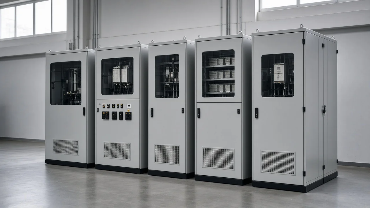
what are capacitor banks? They are assemblies of power-capacitor units connected—and usually equipped with switching, protection, and discharge paths—so the group can be applied as one reactive-power package on a bus or feeder, not as a lone capacitor can.
The sections below name what belongs inside that package, how units are connected, which fixed / automatic / medium-high-voltage labels buyers hear, where banks sit in a power system, and how a packaged CHYN HYTBB cabinet fits that definition. Related guides cover operating benefits and kvar sizing for power factor correction when you need those jobs next.
What a Capacitor Bank Is
A capacitor bank is an assembly of multiple capacitor units connected in series, parallel, or series-parallel so the group reaches a target voltage rating, capacitance, and reactive power (kvar) output.
IEEE Technology Navigator describes banks as assemblies of capacitor units combined for a stated capacitance, voltage, and reactive-power output (IEEE TechNav capacitor banks topic). Independent glossaries use the same object language—a collection or assembly of capacitor units that supplies reactive power locally to support voltage and power factor in transmission, distribution, or industrial networks (eRoots — Capacitor Bank; RatedPower glossary).
In plant language, a shunt capacitor bank is the equipment package you switch, protect, and rate in kvar—not the chemistry of one dielectric film alone. Reactive power is the magnetizing share inductive loads such as motors and transformers need; capacitors supply a leading share of that quantity so the upstream network need not carry as much of it.
The bank’s reactive output also depends strongly on system voltage (it falls when voltage falls), which is why placement and bus voltage class matter on the nameplate. For operating benefits and kvar sizing, see the related guide on capacitor banks for power factor correction.
What Components Belong in a Capacitor Bank
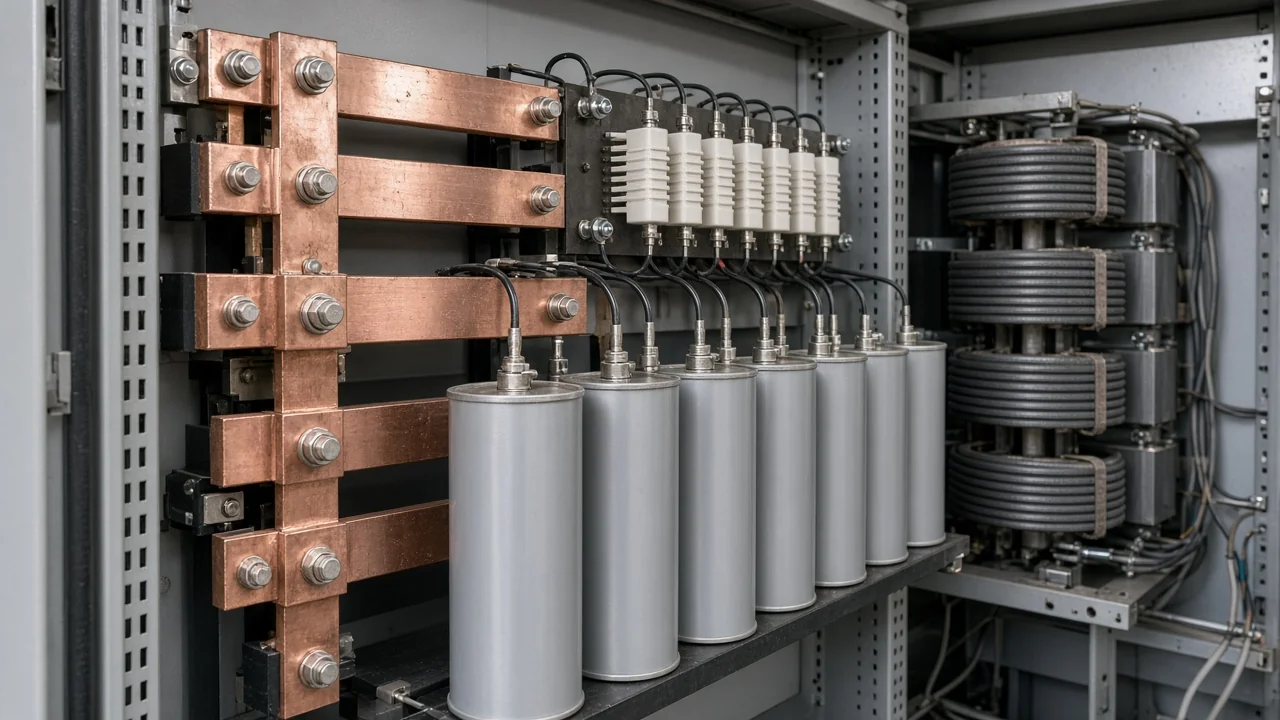
An industrial capacitor bank is more than a rack of cans: each capacitor unit / can sits with switching devices, protection, discharge paths, and often series reactors and a controller.
Education inventories list the usual bill of materials: capacitor units, switching contactors or circuit breakers, fuses or protective relays, discharge resistors, controllers for automatic operation, and busbars or cables (Testbook — Capacitor Bank). On a packaged medium- or high-voltage cabinet such as CHYN’s HYTBB, the live product description names the same family of parts—high-voltage parallel capacitors, reactors, vacuum circuit breakers, current transformers, discharge resistors, and control/protection units (HYTBB product page).
| Component | Role in the bank |
|---|---|
| Capacitor unit (can) | Stores energy in an electric field and supplies capacitive kvar |
| Switching device | Connects or disconnects the bank or individual steps |
| Fuses / protection relays | Isolate failed units and trip on unbalanced or fault conditions |
| Discharge resistor/circuit | Bleed residual voltage after the bank is opened |
| Series reactor (when fitted) | Limits energization inrush and shapes harmonic behavior |
| Controller / CT feedback (automatic banks) | Adds or removes steps as load changes |
| Enclosure, buswork, indicators | Mechanical support, connections, and operator visibility |
A discharge resistor/circuit is part of what makes a bank usable after it opens. Residual voltage remains until that path brings it down; packaged designs commonly target a low residual voltage within minutes so reclosing and maintenance stay controlled.
HYTBB documentation describes a discharge circuit intended to bring residual voltage below 50 V within minutes after disconnection. Read that as a product design statement for the cabinet, not as a listing claim for every market code.
From the field: Leaving excess capacitance online at light load (a leading power factor) is more than a billing curiosity—practitioners note it can drive large inrush during switching and local voltage complaints (Physics Forums — leading PF / capacitor banks). Switching and control therefore belong in the bank object itself.
How Capacitor Units Are Connected in a Bank
Series / parallel connection is how a bank reaches its voltage and kvar targets: series strings raise withstand voltage; parallel groups raise capacitance and kvar. The finished bank may also use a grounded-wye, ungrounded-wye, or delta connection with different protection implications.
Wire units in series when you need higher operating voltage, and in parallel when you need more capacitance or reactive power. IEEE TechNav adds the system-level connection choices—grounded-wye, ungrounded-wye, or delta—each with different implications for transient overvoltage, fault current, and protection sensitivity (IEEE TechNav — Capacitor Banks).
On a drawing, notice whether the bank is one solid block or several switched steps, whether reactors sit in series with the capacitor branch, and how the neutral is treated. Those marks tell you what object you are buying before any sizing spreadsheet.
Back-to-back energization and controlled closing are covered in CHYN’s related article on point-on-wave switching for capacitor banks.
Fixed, Automatic, and Medium/High-Voltage Bank Types
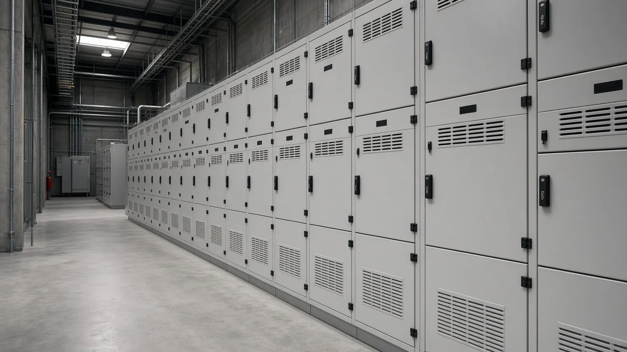
A fixed capacitor bank stays connected whenever its feeder is live; an automatic capacitor bank switches steps with load; a medium voltage capacitor bank or high-voltage package places the same idea on higher-voltage industrial or utility buses.
| Type label | What it is | Typical fit |
|---|---|---|
| Fixed capacitor bank | Permanently connected kvar block | Stable process load or continuous motor demand |
| Automatic capacitor bank | Controller adds or removes stages | Plants whose reactive demand swings through the day |
| Low-voltage bank | Packaged for LV distribution panels / MCCs | Building and light-industrial LV boards |
| Medium voltage capacitor bank / HV package | Packaged for MV/HV buses and substations | Industrial substations and utility feeders |
| Pole-mounted bank | Outdoor distribution-pole package | Feeder voltage support near loads |
Education sources describe fixed banks as simple constant compensation and automatic banks as controller-driven stage switching that tracks changing load (Testbook — types; Payapress — bank configurations). Voltage-class labels describe where the package sits electrically, not a different physics of capacitance.
Stable process floors often keep one kvar block online all shift. Plants that idle large motors overnight usually need stepped switching instead. On drive-heavy sites, reactors or filter branches may still be required accessories.
Where Capacitor Banks Sit in a Power System
Capacitor banks are placed where local reactive support helps a bus, feeder, or plant—commonly in a substation / industrial bus room, outdoor poles, and some transmission or filter applications.
IEEE TechNav lists distribution feeder support, industrial power-factor improvement, harmonic filter banks, and transmission-level reactive compensation among typical contexts (IEEE TechNav — Capacitor Banks). Glossaries add that location strongly affects how much local voltage and upstream reactive loading improve (eRoots).
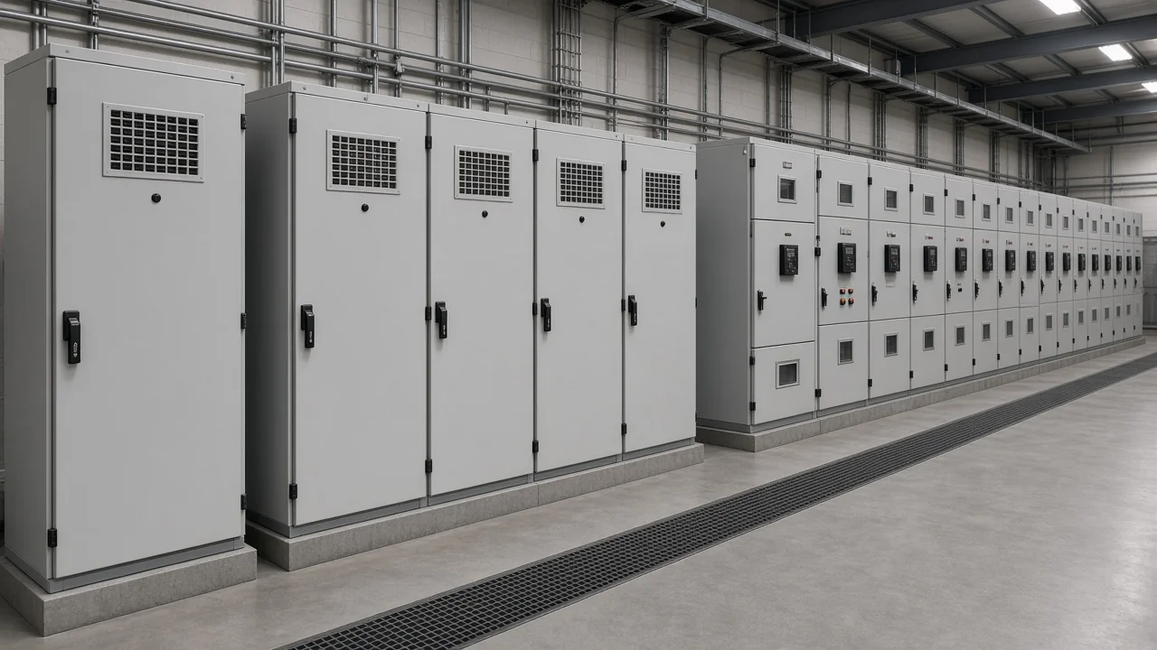
On a one-line diagram, look for the shunt branch off a bus or feeder—not a series path in the main power flow. That shunt placement is part of what the bank is electrically: a parallel reactive device, not a series UPS string.
A house rarely needs an MV cabinet. Residential motor capacitors and utility guidance cover that case; they are outside the industrial bank package defined here.
Capacitor Bank vs Single Capacitor, Battery, and Dynamic Compensators
A bank is a multi-unit package; a battery stores energy chemically for longer discharge; dynamic devices such as SVGs adjust reactive power continuously—so the three solve overlapping but different jobs.
A single capacitor unit can correct a small load, but a bank is the assembled, rated, and usually switched collection of units that a substation or plant treats as one asset. Capacitors and batteries both store energy, yet capacitors hold far less energy for the same size, discharge differently, and are not chemical UPS substitutes (RatedPower — capacitor vs battery).
Dynamic compensators (SVG / STATCOM-class equipment) respond smoothly and quickly compared with stepped capacitor banks. Banks remain attractive for steady or slowly changing reactive support, while their output tracks voltage and often moves in discrete steps (eRoots). “Capacitor bank” therefore does not mean “any reactive device.”
When a Packaged MV/HV Capacitor Bank Product Fits (HYTBB)
When the bus is medium or high voltage, the bank usually arrives as a packaged cabinet or frame that already includes the capacitors, switching, protection, discharge path, and—when required—series reactors.
IEEE 1036 provides application guidance for shunt power capacitors rated 2400 Vac and above and for assemblies of such capacitors (IEEE 1036-2020). Individual shunt capacitor units used inside those assemblies are addressed by IEEE 18 (IEEE 18-2025).
CHYN’s High Voltage Power Factor Compensation Series groups medium- and high-voltage capacitor-bank and related reactive-compensation packages.
The HYTBB medium and high voltage reactive power compensation cabinet is described as a shunt capacitor bank for power-frequency systems in about the 1–35 kV class (parameter table 10(6)–35 kV), with rated capacity from 50 to 20,000 kvar at 50 Hz. The same page lists capacitors, reactors, vacuum breakers, CTs, discharge resistors, and control/protection, with fixed or manual/automatic group switching.
Series-reactor examples on the page include about 4.5–6% for 6 kV systems and 12–13% for 10 kV systems as design illustrations for inrush limiting and harmonic suppression.
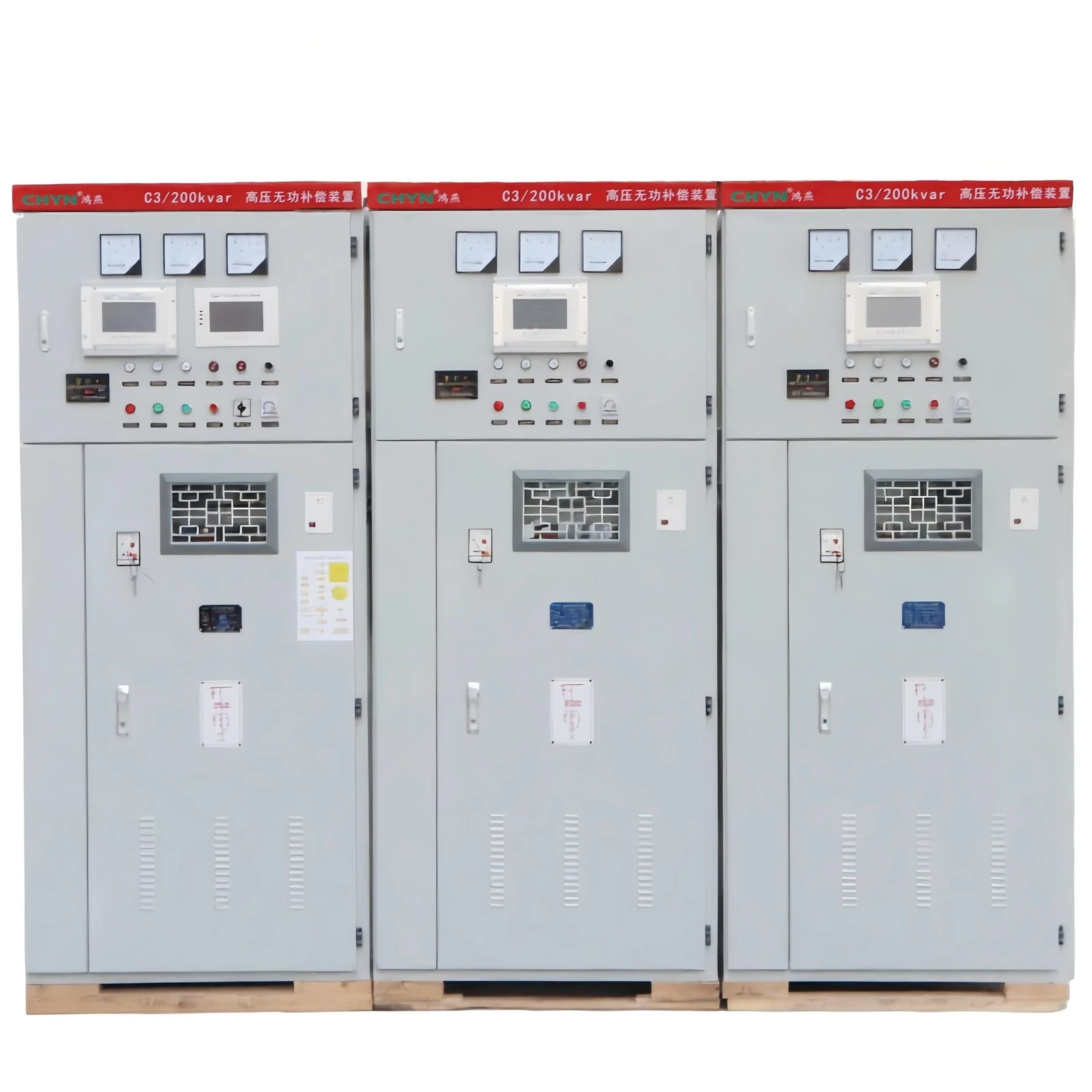
HYTBB fits when you need a packaged MV/HV shunt bank that matches this definition. For power-factor sizing, open the capacitor bank for power factor correction guide. For switching-transient control, open point-on-wave switching.
FAQ
What are capacitor banks in simple terms?
They are groups of power capacitors connected and equipped so they operate as one reactive-power package on an electrical system—typically with switching and protection, not as a single loose capacitor.
What parts are inside a typical industrial capacitor bank?
Expect capacitor units, a switching device, fuses or relays, a discharge path, buswork, and—on many designs—series reactors plus a controller for automatic steps.
Are capacitor banks connected in series or parallel?
Both. Series connections help the bank withstand higher voltage; parallel connections add capacitance and kvar. The finished bank may also use wye or delta system connections.
What is the difference between fixed and automatic capacitor banks?
A fixed bank stays connected whenever its feeder is energized. An automatic bank switches stages on and off as reactive demand changes so the package tracks load instead of staying at one kvar block.
Where are capacitor banks installed in a power system?
Common locations include distribution substations, industrial plant buses and electrical rooms, outdoor poles on feeders, and some transmission or harmonic-filter applications—always as a shunt device off the bus or line.
Is a capacitor bank the same as a battery?
No. Both store energy, but a capacitor bank stores energy in electric fields for reactive-power duty, while a battery stores chemical energy for longer discharge. A bank is not a UPS battery substitute.
What risks come with capacitor banks?
Energizing a discharged bank can produce a short, high inrush current; excess capacitance at light load can create leading power-factor and switching stress; harmonics can interact with bare capacitor branches. Protection, discharge timing, and—when needed—reactors belong in the package definition for that reason.
What is a medium/high-voltage capacitor bank package?
It is a bank built for MV/HV buses—often a cabinet or frame that already integrates capacitors, switching, protection, discharge, and reactors. IEEE 1036 is a common application reference for shunt capacitors rated 2400 Vac and above; CHYN’s HYTBB is one packaged example in that voltage neighborhood.
References
- IEEE Technology Navigator topic page on capacitor bank assemblies
- IEEE 1036-2020 Guide for the Application of Shunt Power Capacitors
- IEEE 18-2025 Standard for Shunt Power Capacitors
- eRoots glossary entry: What is Capacitor Bank?
- RatedPower glossary: capacitor bank in solar plants
- Testbook education page: What is a Capacitor Bank?
- Payapress technical note: capacitor bank definition and inrush context
- Physics Forums discussion: leading PF from overcorrected capacitor banks