
 Zhejiang Hongyan Electric Co., Ltd.





































A shunt capacitor bank for power factor correction supplies leading reactive power so inductive plant loads draw fewer lagging vars from the utility, which raises power factor and usually cuts apparent current for the same kilowatts. The sections below cover how that correction works, how to size a capacitor bank in kvar, when a fixed vs automatic capacitor bank fits, how harmonics and switching change the design, and when a medium- or high-voltage package is the right next step.
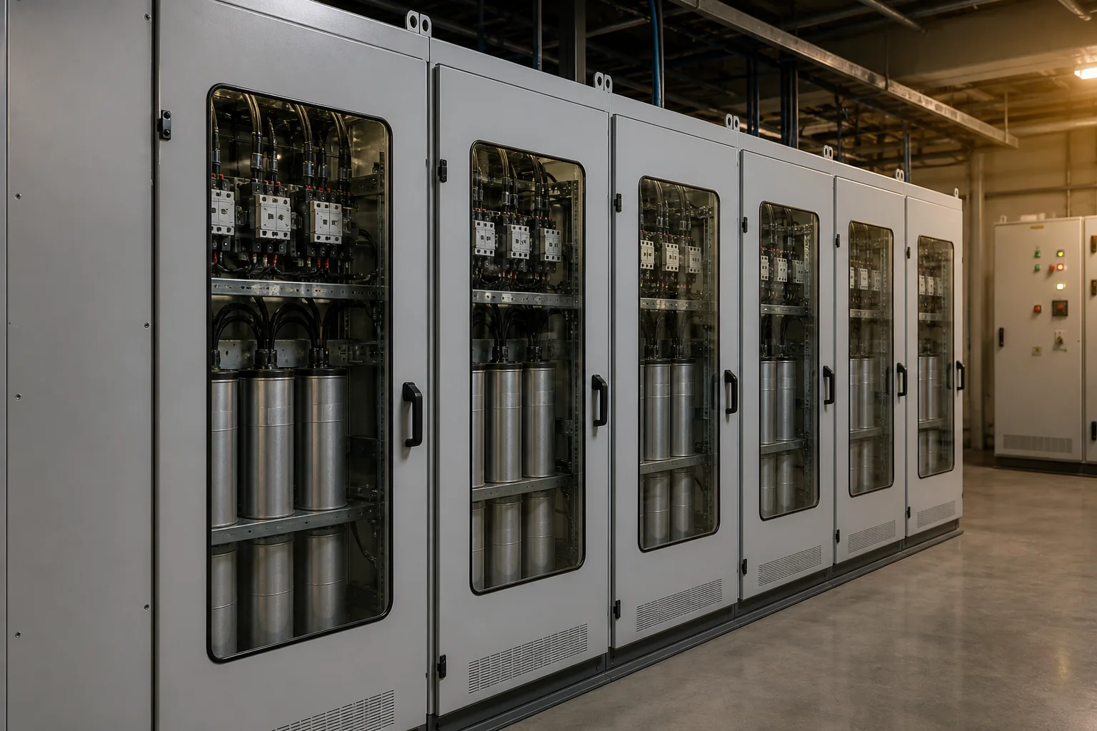
How a Capacitor Bank Corrects Power Factor
A shunt bank supplies leading kvar that cancel part of the lagging reactive power drawn by motors, transformers, and other inductive equipment.
Power factor is the ratio of real power (kW) to apparent power (kVA). When current lags voltage, apparent power rises even though the useful work stays the same, so feeders and transformers carry extra current. Reactive power (kVAR) is the magnetizing share capacitors can supply locally.
Capacitors draw current that leads voltage. Connected in parallel with the load, they inject leading reactive power into the local bus.
The utility then supplies less lagging reactive current for the same kW. That is classic displacement power factor correction—the everyday industrial use of a shunt capacitor bank.
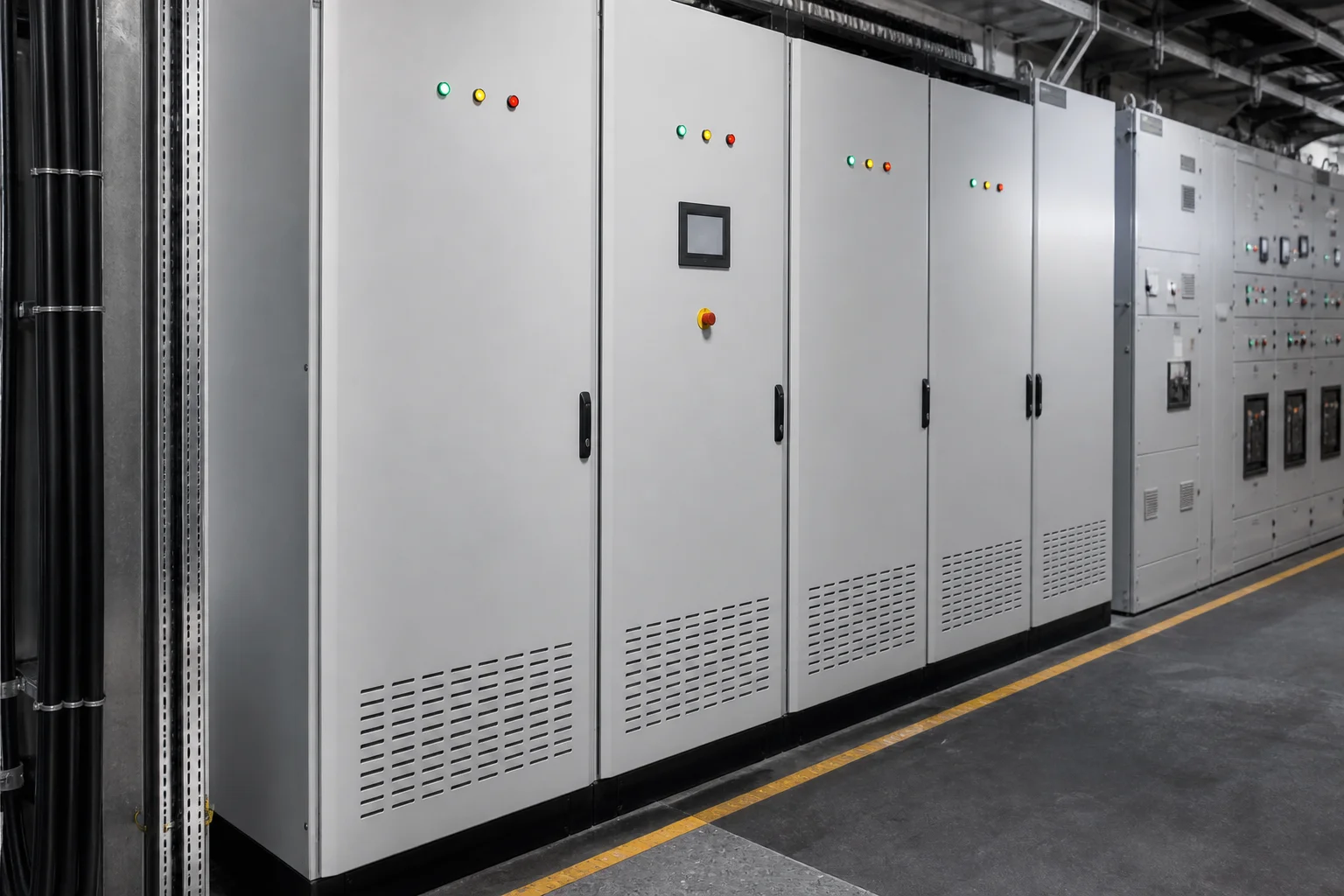
IEEE Technology Navigator describes the same idea for utility and industrial networks: shunt power capacitors generate reactive power locally, reduce line losses, free thermal capacity, and support bus voltage at the point of application (IEEE TechNav — Shunt Power Capacitors).
Encyclopedia treatments of power factor correction make the economic point buyers already feel on invoices: low power factor means more current for the same real power, and utilities often charge industrial customers accordingly (Wikipedia — Power factor / PFC).
What a bank leaves unfinished is harmonic distortion. If nonlinear loads dominate the waveform, you still need a harmonic study—and often reactors or filters—before you celebrate a higher meter PF reading.
How to Size kVAR for Power Factor Correction
Use Qc = kW × (tanφ1 − tanφ2) from measured load, then pick a standard rating—that is the core of how to size a capacitor bank for displacement correction.
Here φ1 is the phase angle of the present power factor and φ2 is the target. Educational calculators state the same relation as Qc = kW × [tan(arccos PF1) − tan(arccos PF2)] (Capacitor bank sizing calculator).
Worked education examples follow (illustrative only).
| Real load | Present PF | Target PF | Calculated Qc | Notes |
|---|---|---|---|---|
| 100 kW | 0.75 | 0.95 | 55.3 kvar | Miniwebtool worked example |
| 200 kW | 0.80 | 0.95 | 84.3 kvar → select ~90 kvar | Keentel 480 V worked example |
Education example: 100 kW from 0.75 to 0.95 needs 55.3 kvar. Education example: 200 kW from 0.80 to 0.95 needs about 84.3 kvar, then select about 90 kvar.
Size from logged kW and PF across a representative cycle, rather than from a single nameplate guess. Peak demand periods and light-load nights both matter: a bank that looks perfect at noon can overcorrect at midnight if it never switches off.
Practical targets often sit near 0.95–0.98 lagging rather than forcing unity on an automatic controller. Chasing 1.00 leaves no room for measurement error and invites a leading power factor when a large motor stops.
After you have a kvar number, round to a standard bank or step size and design protection around the installed rating. On systems with significant drives or rectifiers, finish the harmonic check before you freeze an undetuned design—sizing math alone stops short of a full specification.
Fixed Versus Automatic Capacitor Banks
Fixed fits stable kvar demand; automatic steps track variable load and limit light-load overcorrection.
A fixed capacitor bank stays connected whenever its feeder is energized. It is simple and economical when a continuous process or a single large motor keeps reactive demand almost flat. The risk is obvious: if production drops and the capacitors stay online, the bus can swing leading.
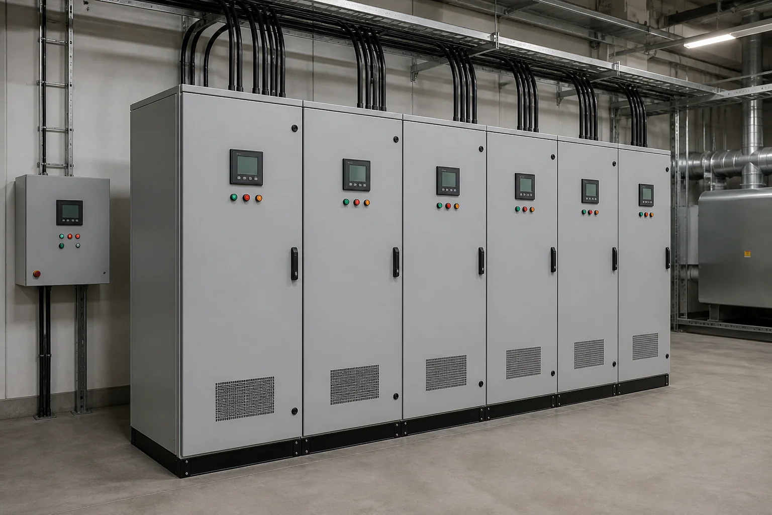
An Automatic capacitor bank / APFC system uses a controller and contactors (or thyristor switches) to add and remove steps. Guides for industrial sites describe stepped banks with roughly half a dozen to a dozen stages as a common pattern for variable plants (ElecCalc industrial PFC guide). That is the usual answer when buyers ask about a fixed vs automatic capacitor bank on a mixed motor floor.
| Architecture | Best fit | Main watch-out |
|---|---|---|
| Fixed capacitor bank | Steady reactive demand | Overcorrection at light load |
| Automatic / APFC stepped bank | Variable plant load | Controller CT location, step size, discharge wait |
| Detuned automatic or fixed bank | Harmonic-rich plants | Reactor percent and study before energizing |
From the field: Excess capacitance and a leading power factor can cause large inrush currents during switching events and local voltage complaints—so adding kvar without load profiling can backfire (Physics Forums — capacitor bank PFC thread).
Static correction mounted on individual motors has a second limit. Community engineering threads warn that oversizing fixed capacitors on a motor can create resonant circulating currents as the machine coasts down after disconnect (Physics Forums — over-correcting inductive loads). Keep motor-mounted kvar below the magnetizing need the motor vendor allows.
Harmonics, Resonance, and Detuned Banks
Banks fix displacement power factor; nonlinear loads need a study and often a Series reactor / detuned bank before a bare capacitor string is safe.
Capacitive reactance falls with frequency while source inductance rises. Somewhere they meet, and if that parallel resonance lands near a harmonic the plant already produces—commonly the 5th or 7th from six-pulse drives—the bank can overheat, fuse, or amplify voltage distortion.
A common engineering screen used in consultancy education is to treat the system as harmonic-rich when nonlinear load exceeds roughly 15–20% of the bank or transformer rating, then model before applying undetuned capacitors (Keentel capacitor bank PFC guide). Detuned banks add a series reactor so the branch resonates below the dominant harmonic. That changes the product decision beyond buying more kvar.
On CHYN’s HYTBB medium- and high-voltage compensation cabinet page, series reactors are described as limiting inrush and suppressing harmonics, with example reactor percentages such as 4.5–6% on stated 6 kV systems and 12–13% on stated 10 kV systems. Those figures belong to that product family’s published notes—verify them against your study before copying them elsewhere.
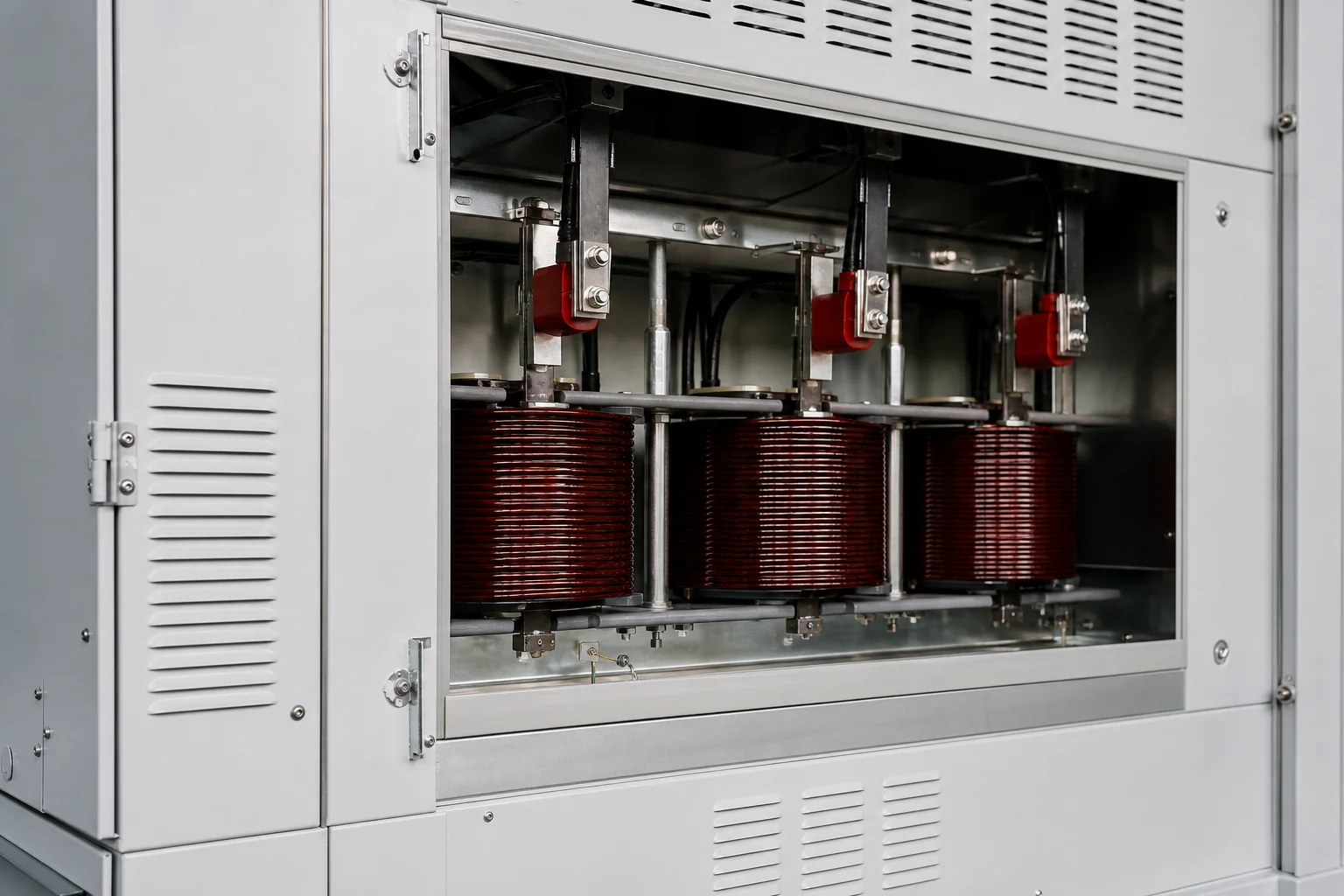
If distortion power factor is the real problem, expect active filters or tuned filter stages in the conversation. Capacitor banks remain useful for fundamental lagging vars while harmonic mitigation handles the waveform job.
Discharge, Inrush, and Safe Switching Practice
Plan discharge time, inrush limiting, and reclose delays—alongside nameplate kvar.
A discharged capacitor initially looks almost like a short circuit to a sudden voltage step. Educational treatments of capacitor bank inrush current describe peaks on the order of about 10–20 times rated current for single-bank energization, lasting only milliseconds, with the exact multiple set by source impedance, switching angle, and capacitance (Payapress — capacitor bank inrush).
Back-to-back switching—closing one bank while another is already live on the same bus—can be harsher still. Series reactors, controlled switching, and operating timers are the usual mitigations. For controlled closing timing detail, see CHYN’s related reading on point-on-wave switching for capacitor banks.
Discharge circuit hardware bleeds residual voltage after the bank opens so the next close avoids a charged-bank surprise. HYTBB product documentation describes a discharge design that brings residual voltage below 50 V within minutes after disconnection.
In United States installations governed by NEC Article 460 for capacitors at 1000 V nominal and below, education summaries cite a tighter ≤50 V within one minute discharge rule and conductor ampacity of at least 135% of rated capacitor current. Keep that framing as US installation-code context for LV work; it does not certify CHYN equipment under NEC from this page alone (Keentel guide NEC 460 summary).
Buyers should write three switching lines into the RFQ: expected operations per day, minimum reclose delay after open, and whether reactors or controlled switching are mandatory on that bus.
When an MV/HV Capacitor Bank Package Fits
Use MV/HV packaged banks when the compensated bus is medium or high voltage, or when kvar demand and switchgear class outgrow low-voltage APFC cabinets.
Low-voltage automatic cabinets remain a good fit for many 400/480 V distribution boards with stepped kvar and a PF controller. They fit poorly when the plant problem sits on a 6–35 kV industrial or distribution bus, when outdoor frame or box-type banks are required, or when utility interconnection studies assume shunt compensation at MV/HV.
IEEE Std 1036 is a widely cited application guide for shunt power capacitors rated 2400 Vac and above, covering utilization from simple units to complex banks (IEEE 1036-2020). That standard framing helps buyers separate “buy an LV APFC panel” from “specify a medium-voltage shunt bank with protection, reactors, and switching duty.”
Optional secondary path: if your only load is a low-voltage MCC with moderate kvar and light harmonics, start with CHYN’s low-voltage power factor compensation series and keep the HV pathway for the MV bus case.
CHYN Medium and High Voltage Capacitor Bank Options
Review the High Voltage Power Factor Compensation Series hub and the HYTBB cabinet when you need a documented MV/HV shunt compensation package.
CHYN’s High Voltage Power Factor Compensation Series groups medium- and high-voltage reactive compensation products for industrial and distribution projects. A concrete example is the HYTBB medium and high voltage reactive power compensation cabinet, described on the live product page as a shunt capacitor bank for power-frequency systems in the roughly 1–35 kV class, with rated capacity spanning 50–20,000 kvar, fixed or manual/automatic group switching, series reactors, and discharge provisions.
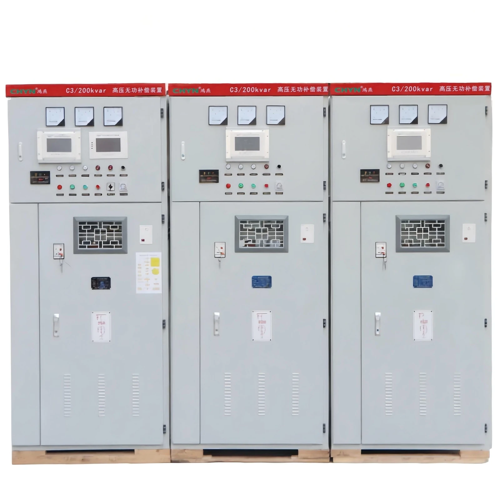
The same page states that the design can raise system power factor to 0.95 or higher and notes a line-current reduction in the 10–20% range under the conditions it describes. Confirm those product-page statements against your measured load before treating them as project energy-savings targets.
Bring voltage class, measured PF and kW profile, target PF, harmonic spectrum or drive share, indoor/outdoor preference, and switching frequency to the enquiry. That package of facts beats a bare “need capacitor bank” email every time.
FAQ
What is a capacitor bank for power factor correction?
It is a group of power capacitors—often with switching, protection, discharge devices, and sometimes reactors—connected in shunt to supply leading kvar and raise displacement power factor at the application bus.
How do I calculate the kVAR rating of a capacitor bank?
Start from Qc = kW × (tanφ1 − tanφ2) using measured present and target power factors, then select the next practical standard rating and confirm it against light-load and harmonic constraints.
Should I choose a fixed or automatic capacitor bank?
Choose fixed when reactive demand is stable; choose automatic stepped control when load swings would otherwise leave you undercorrected at peaks or leading at light load.
Will a capacitor bank fix harmonics or distortion power factor?
No. Shunt capacitors correct fundamental lagging vars. Harmonic-rich plants need a study and often detuned reactors or dedicated filters.
Why is inrush current a concern when switching capacitor banks?
A discharged bank accepts a fast voltage step, so energization can draw a short high-frequency surge many times rated current; back-to-back banks raise the stress further.
How does capacitor discharge time affect reclosing?
Residual voltage must fall before a safe reclose. Product designs and installation codes specify discharge targets; ignoring them turns the next close into a charged-bank transient.
When does an MV/HV capacitor bank package make sense?
When the bus to be corrected is medium or high voltage, when outdoor or switchgear-integrated HV packages are required, or when kvar and duty exceed what an LV APFC cabinet should carry.
Can I overcorrect a motor with a fixed capacitor?
Yes. Oversized motor-mounted capacitors can create resonant voltages and currents as the motor coasts down; keep static correction within the motor’s allowed magnetizing margin.
References
- IEEE 1036-2020 — Guide for the Application of Shunt Power Capacitors
- IEEE Technology Navigator — Shunt Power Capacitors
- Wikipedia — Power factor (power factor correction)
- Miniwebtool — Capacitor bank sizing calculator
- Payapress — What is capacitor bank inrush current?
- Keentel Engineering — Capacitor banks & power factor correction guide
- Physics Forums — Power factor correction capacitor bank thread