
 Zhejiang Hongyan Electric Co., Ltd.





































An apfc relay control wiring diagram shows how the controller’s sensing inputs and step-command contacts connect so capacitor banks can be switched toward a target power factor. Read CT and Aux/measurement terminals first, then COM plus K1–Kn (or C1–Cn) step outputs, then the Auto/Manual and alarm branches that sit beside them. The pages below stay on relay-terminal literacy—not a full panel power-circuit build—and point you back to the manufacturer pinout for exact numbers.
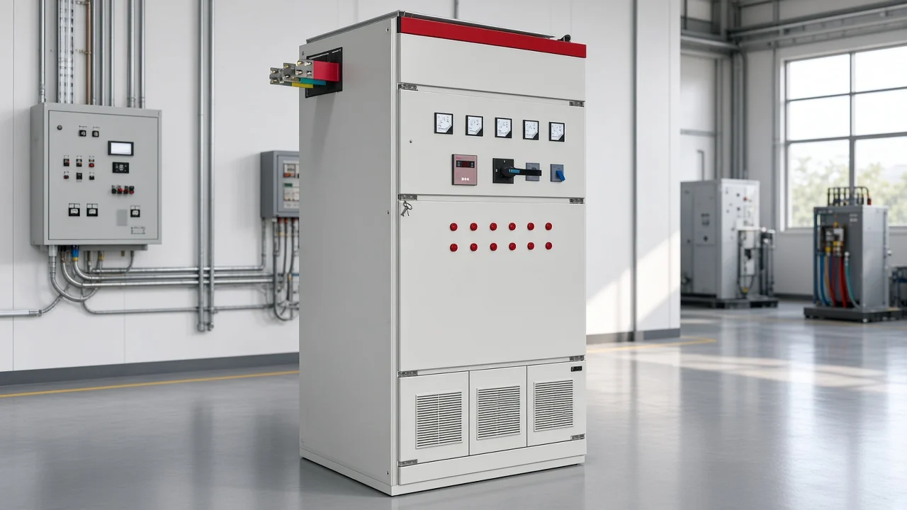
What an APFC Relay Control Wiring Diagram Shows
It maps sensing inputs and step commands so the controller can switch capacitor steps toward a target PF.
On paper, the APFC relay / controller diagram usually has three families of terminals. Sensing covers voltage (or Aux) and the CT / current transformer secondary. Command covers step output contacts—the dry contacts that close to a common (COM) and energize each contactor coil for a capacitor bank step. Status covers each alarm / fault contact that does not switch banks by itself.
Those families answer different questions. Sensing tells the relay what the network is doing. Command tells contactors when to close. Status tells an operator or PLC that something needs attention. Mixing the families—treating a step output as a capacitor power feed, for example—is the most common reading error on these sheets.
If you need the broader definition of what the controller does before you read terminals, start with the related explainer on what an automatic power factor controller is at https://chynele.com/blog/what-is-automatic-power-factor-controller/.
How to Read CT and Voltage-Sensing Terminals
Match the CT secondary ampere tap to the relay, keep the CT upstream of load and bank, and follow same-phase or quadrature V/I pairing.
Most relays accept a single load CT secondary at a standardized rating—commonly 1 A or 5 A. Labels often read S1/S2, or COM plus a matching ampere tap. The APFC controller CT connection must match that rating on the terminal block; mixing a five-amp secondary into a one-amp-only input (or the reverse) is a drawing mismatch, not a field improvisation.
Placement matters as much as polarity. On a typical automatic PF scheme, the CT sits upstream of both the compensated load and the capacitor bank connection so the relay sees the current that still needs correction. A CT parked only on the bank feeder tells a different story and can leave the controller chasing the wrong reactive demand.
Voltage sensing rides with that current input. Two common patterns appear on diagrams: line-to-neutral voltage on the same phase as the CT, or line-to-line voltage on two phases with the CT on the third (quadrature). The sheet’s phase table—not memory—decides which pair you have.
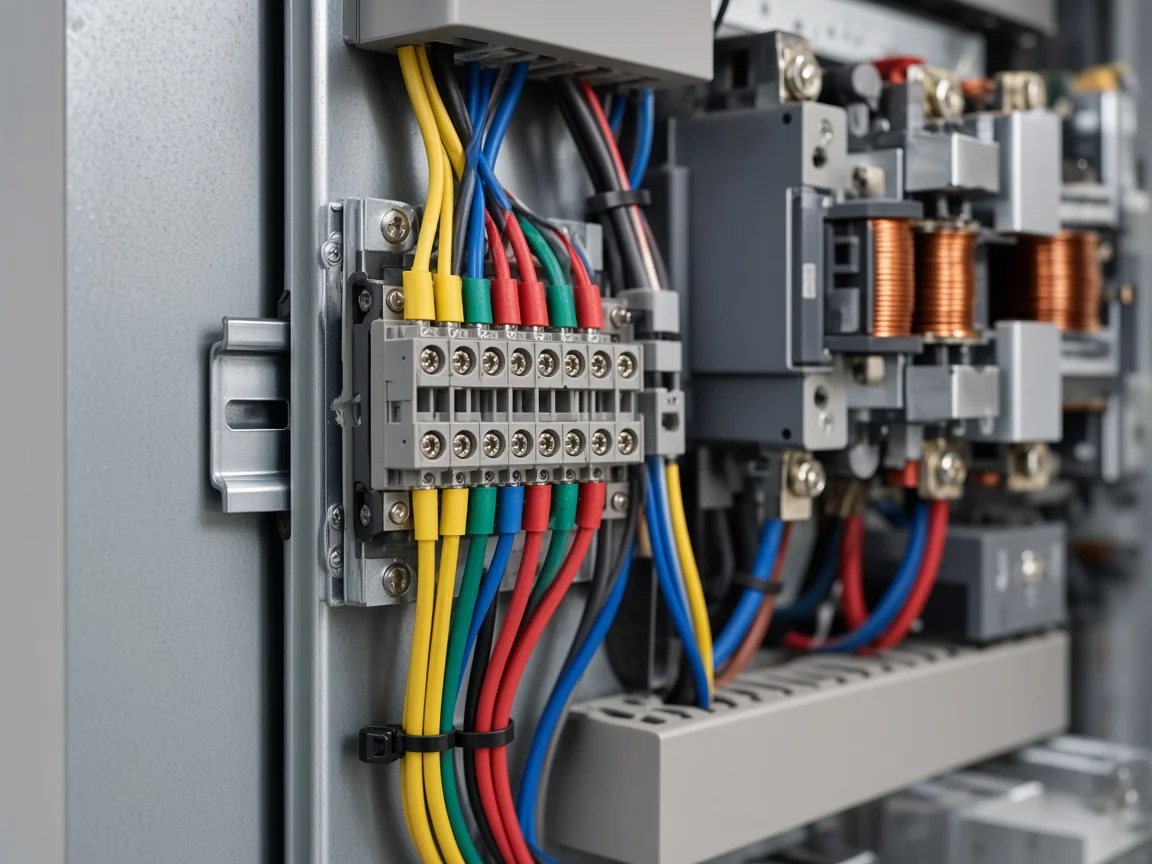
Important: Never leave an energized CT secondary open. If you must lift wires, short the secondary first (a shorting block is the usual shop practice). An open secondary can drive hazardous voltage and damage the CT — source: https://en.wikipedia.org/wiki/Current_transformer
Field discussions often add two practical habits: bond the secondary reference (commonly S2/C) the way the device drawing shows, and keep CT orientation paired with the same voltage phases the relay expects. Those habits show up again when commissioning flags a CT polarity error.
Auxiliary Supply and Measurement Voltage on the Diagram
Aux/measurement terminals take fused control voltage as the relay specifies—often L1/L2 from a control MCB.
Many sheets label a fused Aux feed separately from the measurement voltage; some relays share one pair for both. Either way, the diagram shows where control power enters the relay and which phases feed the PF calculation.
A frequent educational pattern takes L1/L2 from the R–Y (or equivalent) bus through a small control breaker, then lands those conductors on the relay’s Aux terminals. The same drawing may also land a phase onto the step-output COM so contactor coils see a defined coil voltage when a step closes.
Keep Aux fusing on the drawing in view. A missing control fuse or a feed taken from a phase that sags independently of the measurement pair can drop contactors and force awkward reconnect cycles. When the diagram notes that coil supply and measurement voltage should come from the same phase family, treat that note as a reading rule, not optional artwork.
Step Outputs K1–Kn, COM, and Contactor Coils
Step contacts are usually dry N.O. outputs to contactor coils via COM—not direct capacitor power feeds.
This is where APFC relay step outputs earn their name. Terminals labeled K1…Kn or C1…Cn are almost always potential-free normally-open contacts. COM (sometimes a shared bar across steps) receives the contactor-coil phase. When the relay commands a stage, that step contact closes and the coil sees voltage; the other coil terminal returns to neutral (or the coil return shown on the sheet).
Read the arrow of power carefully. Capacitor power still comes through the power contactors and their breakers. The relay only commands those coils. Wiring bank power into Kn is a misread of the control diagram.
| Terminal family | Typical labels | What it does on the diagram |
|---|---|---|
| Step common | COM, C-COM | Coil-phase feed shared by step contacts |
| Step outputs | K1–Kn, C1–Cn, R1–Rn | Close to COM when that capacitor step is ON |
| Coil return | Neutral, N, or coil A2 | Completes the contactor coil circuit |
| Coil protection | RC snubber / MOV (shown across coil) | Limits inductive kick that can pit step contacts |
Tip: Diagrams and manuals commonly show an RC snubber or MOV across each contactor coil. That detail protects the relay’s step contacts from inductive kick when coils drop out — source note: common APFC wiring education pattern (see References).
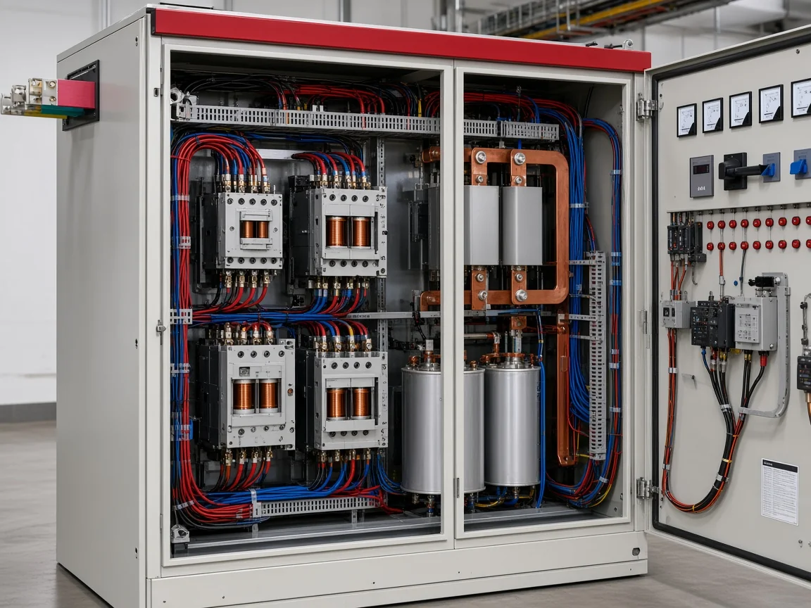
Alarm and Fault Contacts on the Relay Diagram
Alarm contacts are separate from step outputs and typically signal sensing or compensation faults.
Look for a dedicated alarm, ALM, or fault contact set—often a change-over or N.O. contact rated for a lamp, buzzer, or PLC input. Those contacts do not replace K1–Kn. They announce conditions such as over-voltage, under-voltage, CT polarity trouble, under-compensation, or over-compensation, depending on the relay’s menu.
When you trace the sheet, keep alarm wiring on its own path. Sharing an alarm conductor with a step output invites false bank commands or silent alarms. Commissioning screens that blink “CT polarity” or similar codes usually light this contact while the banks are still off—another reason to finish sensing checks before trusting Auto mode.
Auto and Manual Paths Beside the Step Outputs
Many diagrams route Kn into the Auto side of a local selector while Manual uses push buttons.
A control wiring diagram of apfc panel practice often places an Auto / Manual mode selector between each step output and its contactor coil. In Auto, the relay’s Kn feed reaches the coil. In Manual, local push buttons (or a hand switch) drive the same coil so technicians can force a step without waiting for the PF loop.
Reading that branch prevents two mistakes. First, leaving every selector in Manual makes a healthy relay look “dead.” Second, paralleling Manual and Auto feeds without the selector logic can fight the relay and weld contacts. The diagram’s selector common usually points at coil A1; Auto and Manual terminals are the two ways that common can be energized.
Common Terminal Labeling Patterns (Without a Brand Pinout)
Labels differ (K vs C, L1/L2 vs Aux), but the four terminal families stay the same.
Brands rename the same jobs. Some print K1–K12; others print C1–C16; Selec-style sheets may use R1…Rn. Aux may appear as L1/L2, Aux1/Aux2, or Um1/Um2 for measurement voltage. CT inputs may be S1/S2 or COM with a one-amp or five-amp tap. None of those renames change the reading method: identify sensing, identify step COM + outputs, identify alarm, identify Auto/Manual.
| Pattern you see | Usually means | Confirm on the sheet |
|---|---|---|
| S1 / S2 or COM + 1A/5A | CT secondary into the relay | Secondary rating and phase pairing |
| L1/L2, Aux, Um1/Um2 | Control / measurement voltage | Fuse rating and phase set |
| COM + K1…Kn or C1…Cn | Step command contacts | Coil voltage on COM, not capacitor power |
| ALM / Fault / Aux DO | Status contact | Separate from step COM |
| Auto / Man / PB | Local authority over a coil | Selector common to coil A1 |
This table is a literacy aid, not a CHYN pinout. Exact terminal numbers always come from the relay’s own drawing.
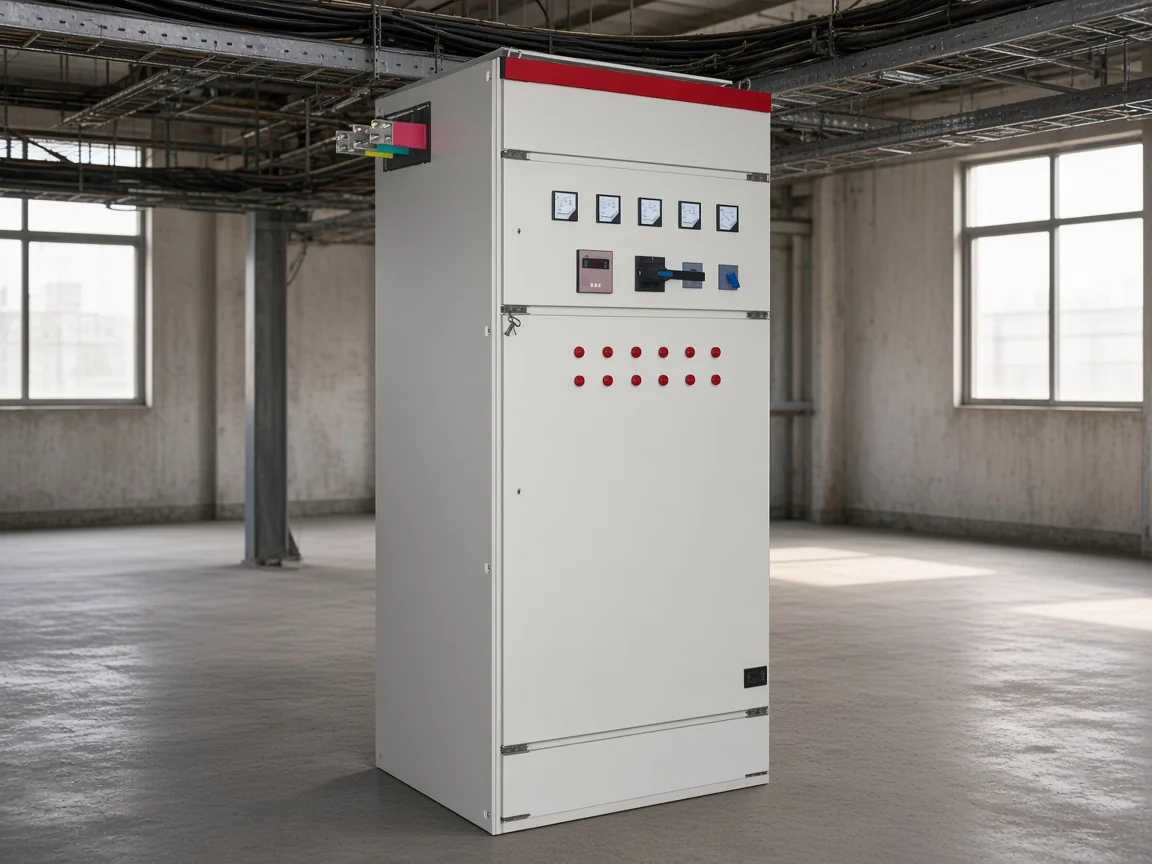
Pre-Energize Checks When the Diagram Looks “Done”
Short CT safely before changes; verify polarity, coil suppression, and Auto/Manual position.
Walk the drawing once more with the panel cold. Confirm the CT is upstream of load and banks, secondary rating matches the relay, and polarity marks face the direction the manufacturer shows. Confirm Aux fuses, COM coil phase, and snubbers across coils. Set selectors to Manual for first step tests, then to Auto only after sensing looks sane.
If the relay reports CT polarity error—or shows negative active power with all banks off—stop and reverse the CT secondary leads (after shorting) or correct the phase pairing. Do not “fix” that fault by stacking more capacitor steps. Sensing has to be honest before Auto mode can be trusted.
When a Static LV Compensation Package Fits This Wiring Job
HYTBBJ fits relatively steady inductive loads needing automatic capacitor-group switching.
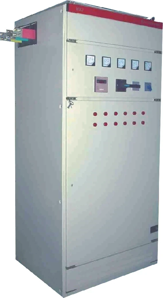
Once the relay diagram is readable, the remaining decision is which compensation package the contactors actually switch. For distribution systems with relatively steady inductive loads in manufacturing, buildings, and public facilities, CHYN’s HYTBBJ Series low-voltage static reactive power compensation system is built to switch capacitor groups from measured reactive demand or power factor.
The live product page states that HYTBBJ supports both manual and automatic modes, offers loop/group/sequential switching styles, and monitors three-phase voltage, current, power factor, and compensation status. It lists an adjustable capacitor switching delay from 0 to 120 seconds with a special fast mode within about one second, plus protection covering over-voltage, under-voltage, over-current, short circuit, capacitor fault, and switching error. The same page states a typical harmonic current reduction of 20%–30% as a product claim for that series—not a universal industry guarantee.
Browse the low-voltage power factor compensation series when you need static versus dynamic family context. Fast, highly fluctuating reactive demand may need a dynamic package instead; we do not invent wiring claims for that class here.
FAQ
Where should the CT be on an APFC relay control wiring diagram?
Place the load CT upstream of both the compensated load and the capacitor bank connection so the relay sees the current that still needs correction. A CT only on the bank feeder usually misrepresents demand.
What do S1 and S2 mean on the CT terminals?
They mark the CT secondary polarity into the relay. Match the one-amp or five-amp rating, keep one secondary reference bonded as the device drawing requires, and never open an energized secondary without shorting it first.
What is the COM terminal on step outputs?
COM is the shared side of the potential-free step contacts. It usually carries the contactor-coil phase so each Kn/Cn can close and energize its coil.
Are K1–Kn the same as C1–Cn?
Functionally they are the same family: numbered step outputs. Brands rename them (K, C, or R). Always confirm the count and COM arrangement on that relay’s sheet.
How do Auto and Manual paths show up on the diagram?
Look for selectors or hand switches between step outputs and coils. Auto feeds the relay command; Manual feeds local push buttons for forced step tests.
What does the alarm/fault contact do?
It is a status contact for conditions such as voltage faults, CT polarity trouble, or under/over compensation. It does not replace the step outputs that drive contactor coils.
What if the relay shows a CT polarity error?
With banks off, reverse the CT secondary (after shorting) or correct phase pairing per the manual. Do not add more steps hoping the alarm clears.
Does a literacy guide replace the manufacturer pinout sheet?
No. Shared labeling patterns help you read any sheet faster. Exact terminal numbers and fuse sizes still come from the relay manufacturer’s drawing.
References
- Current transformer — Wikipedia — authority overview of CT secondary ratings and open-secondary hazards.
- Automatic power factor controller — Electricity Forum — independent technical education on APFC measurement and capacitor switching.
- APFC controller panel wiring diagram and connection — ETechnoG — independent technical walkthrough of Aux, CT, step COM, and Auto/Manual paths.
- Which terminal (S1 or S2) of the current transformer will you ground? — Reddit r/electricians — community forum discussion of CT secondary bonding, shorting blocks, and phase pairing around PF controllers.