
 Zhejiang Hongyan Electric Co., Ltd.





































For power-factor work a capacitor bank connects in parallel with the bus or load it corrects, and inside its own enclosure the capacitor units sit in series-parallel groups. Both halves of the usual answer to are capacitor banks connected in series or parallel therefore hold true, at different levels of the same equipment. The third device people fold into the same question, a series capacitor, sits in the line itself and does a different job.
The Short Answer: Parallel to the Bus, Series-Parallel Inside the Bank
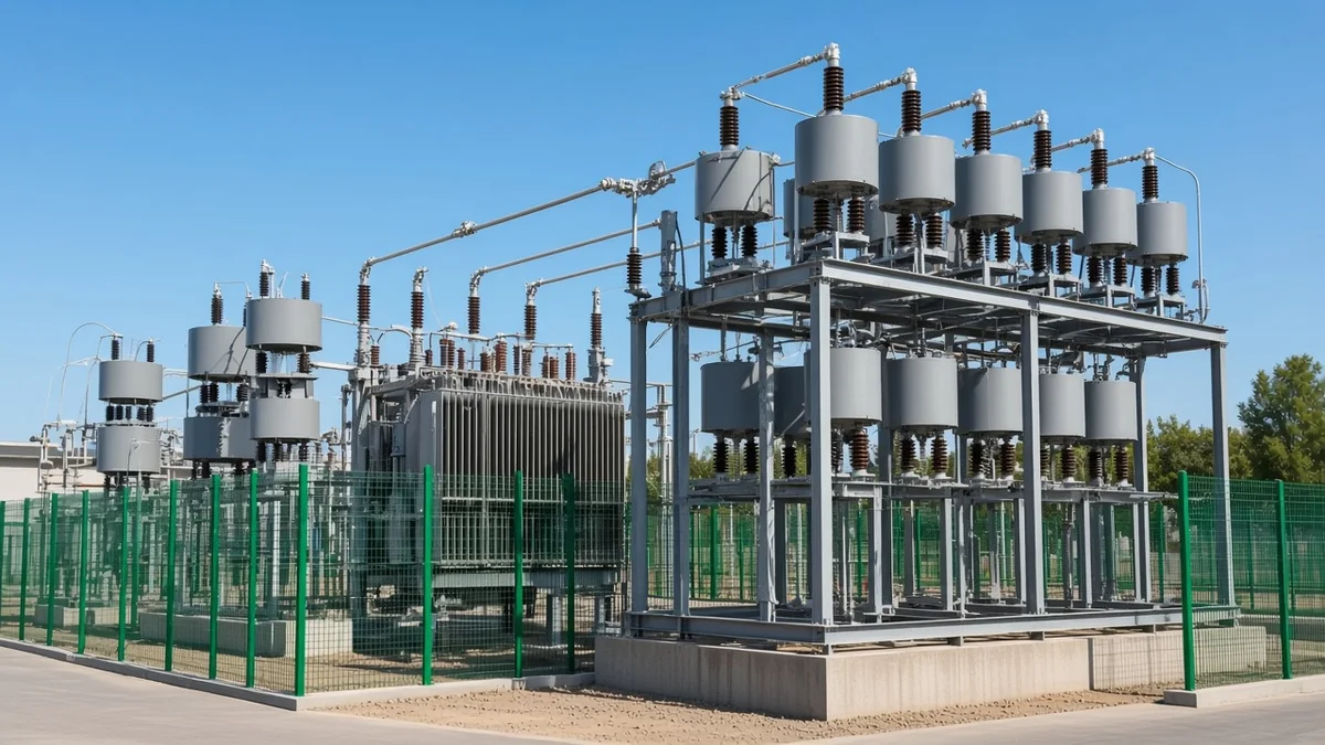
Where you stand decides which answer you get. From the busbar the shunt capacitor bank connection looks like one more parallel branch hanging off the switchgear, drawing leading current and pushing reactive power back into the system. Open the same bank's door and the picture flips: dozens of capacitor units tied side by side and stacked end to end.
| Where you are looking | Connection you will find | Why it has to be that way |
|---|---|---|
| Between the bank and the bus | Parallel, also called shunt | The bank can only inject reactive current if it sees the full bus voltage across its terminals |
| Between units inside one phase | Parallel within a group, groups in series | Parallel units add up to the kvar you ordered; series groups share out a bus voltage no single unit could hold |
| Between the steps of an automatic bank | Parallel, all on the same bus | Each step is an independent branch the controller can connect or disconnect |
| In a transmission line with a series capacitor | Series with the line conductor | Cancelling line reactance requires the load current to flow through the capacitor |
Keep those four rows straight and most of the confusion around this question disappears. The rest of the sections below work through each row with the detail a buyer or plant engineer actually needs on site.
Shunt Banks and Series Capacitors Do Two Different Jobs
Shunt and series capacitors share a component and nothing else. A shunt bank sits across the bus to supply reactive current locally, which lifts the power factor and takes magnetising current off the upstream transformer and cables; low power factor means extra current for the same useful work, and that extra current is what the bank removes. A series capacitor instead sits in the path of the load current, where it cancels part of the line's inductive reactance.
Practitioners keep the two straight by what each one controls. In one engineering discussion of the two capacitor families, an engineer put it plainly: parallel capacitors handle voltage magnitude and power factor, while series capacitors belong in very long transmission lines. Shunt devices support the voltage at a point; series devices shape the power flow along a path.
That difference explains why nobody wires a plant compensation bank into a feeder. Insert a capacitor in series with the load and the total circuit impedance barely changes, so the arrangement keeps drawing much the same reactive power and the correction never arrives — the circuit-theory case against series placement also warns that the series reactance can drive the voltage across the capacitor past its rating.
Inside One Bank: Parallel Units for Kvar, Series Groups for Voltage
Inside the enclosure the two connections do separate arithmetic. Put capacitor units side by side across the same two points and their capacitance adds, which is how a bank reaches 600 kvar or 6,000 kvar from units of a few hundred kvar each. Stack those parallel bundles end to end and the bus voltage divides between them, which is how a 35 kV bank is built from units rated for a fraction of that.
The vocabulary follows the same hierarchy, and knowing it makes quotations readable. Substation practice names the levels in order: units wired side by side form a group; several groups in series form a string, sometimes called one phase leg; strings can themselves be paralleled to reach a larger phase rating. A quote listing 24 units as two series groups of twelve describes a very different machine from one listing twelve series groups of two, even when the nameplate kvar matches.
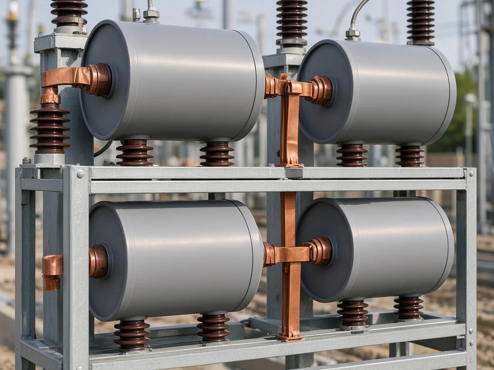
Group size also carries a hard electrical limit rather than a free choice. Take one unit out of a series group and the remaining units in that group pick up its share of the voltage, so the group has to be populated densely enough that the survivors stay inside their rating.
Important: group size follows an electrical limit rather than a packaging preference, and series and parallel circuits explain why the voltage redistributes at all. When a unit in a series group fails, the remaining capacitors of that group must not be left above 110% of rated voltage.
If the internal layout of a bank is new to you, our overview of what capacitor banks are walks through the components before the connection logic.
Three-Phase Forms: Delta, Star, Double Star, and H Connection
Three-phase connection form decides two things at once: the voltage each capacitor has to withstand, and what an unbalance relay can see when a unit fails. Delta, single star, double star and the H arrangement cover almost everything in service, and published connection and composition guidance for LV, MV and HV banks records delta as the most common mode below 12 kV.
A capacitor bank wye connection ties one end of every phase group to a shared star point, while a delta connection closes the three phase groups on themselves between the lines. Capacitors in a star see only phase-to-neutral voltage, so reaching the same reactive power as a delta arrangement takes three times the capacitance — the same reason a delta capacitor carries a line-to-line voltage rating while its star equivalent carries a line-to-neutral one.
| Connection form | Voltage on each capacitor | Typical use | What unbalance detection sees |
|---|---|---|---|
| Delta | Line-to-line | Lower-voltage correction panels, commonly below 12 kV | Little to detect; one series group rated for full line voltage |
| Single star, neutral isolated | Phase-to-neutral | Medium-voltage bus banks | Neutral-point voltage or open-delta voltage shift |
| Single star, neutral earthed | Phase-to-neutral | Higher voltage classes with surge exposure | Neutral current, with a path for zero-sequence current |
| Double star | Phase-to-neutral | All powers and voltages where sensitive protection matters | Current between the two star points |
| H arrangement | Phase-to-neutral, split per leg | Large high-voltage banks with many paralleled units | Bridge current per phase, the most sensitive of the group |
Double star earns its popularity by splitting the bank into two matched halves. Each half forms its own star, the two star points join through a current transformer, and a balanced bank leaves that transformer carrying nothing; one failed element unbalances the halves and the difference current appears immediately. A worked double-star example with an isolated neutral shows twenty-four units arranged as two stars, each phase holding two units in series and two such strings in parallel.
Neutral treatment is the last decision in this group and it cuts both ways. An earthed star point improves behaviour against transient overvoltage, yet it also opens a route for zero-sequence current and harmonic current into the bank, which is why plenty of medium-voltage banks keep the ungrounded neutral instead.
Why an Automatic Bank Parallels Several Steps on One Bus
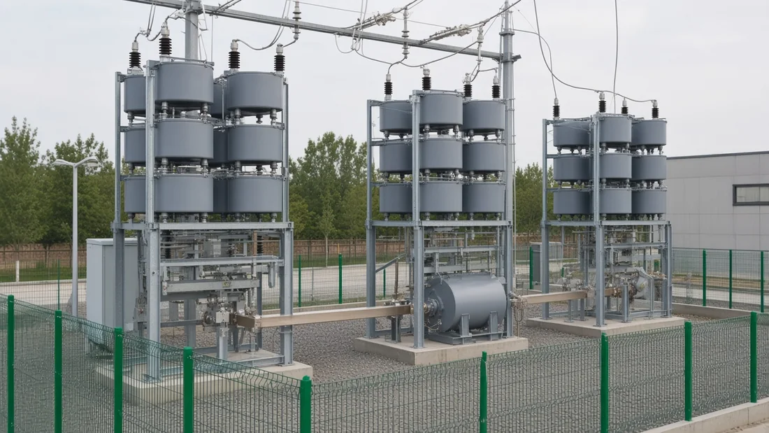
Every capacitor bank step in an automatic bank runs alongside the others, never behind them. A power-factor controller watches the reactive demand and switches blocks of capacitors in and out to hold the target power factor, and every block it commands hangs off the same busbar through its own contactor or vacuum switch. Switching step three therefore changes how much kvar is connected; it does nothing to the electrical position of steps one and two.
This matters when someone traces a single-line diagram for the first time. The steps look stacked on the drawing because they are drawn one under another, which reads like a series chain until you follow the busbar across the top of each branch. Each branch typically carries its own switch, its own fuses and often its own series reactor, and those reactors sit in series with the capacitors of that branch alone.
One caveat belongs here and then we will leave it. Energising a capacitor step next to steps that are already live produces a fast transient, and the timing and reactor choices that manage it are a topic of their own — our note on point-on-wave switching for capacitor banks covers that ground.
Reading the Connection From a Nameplate, Model Code, and Single Line
Three clues tell you the connection of a bank in front of you without opening anything. The type code on the enclosure often encodes it as a letter, the capacitor voltage rating reveals whether the units see line-to-line or phase-to-neutral voltage, and the single-line diagram draws the star point or the closed triangle outright.
| Clue | What to look at | What it usually means |
|---|---|---|
| Type or model code | Connection letter in the designation string | A dedicated letter for single star and another for double star, often paired with the protection letter |
| Capacitor voltage rating | Unit rating against system voltage | Equal to line-to-line points to delta; roughly line voltage divided by root three points to star |
| Protection method named | Open-delta, phase-voltage differential, or neutral-point unbalance | Open-delta travels with single star; neutral-point unbalance travels with double star |
| Single-line diagram | Symbol at the bottom of the three capacitor columns | A joined star point, a closed triangle, or two star points bridged by a current transformer |
| Unit count per phase | Units per group and groups per phase | Reveals how voltage and kvar were split before you ever read the nameplate |
CHYN's own high-voltage pages make that letter-and-protection pairing explicit rather than implied. On the outdoor frame-type reactive power compensation device, an A in the type code marks the single-star wiring configuration and pairs with open-delta overvoltage protection, while a B marks the double-star configuration and pairs with neutral-point unbalanced current protection.
Tip: read the protection method first when the type code is unfamiliar — a bank using neutral-point unbalance protection has to have two star points for that relay to compare, as the connection and composition guidance sets out.
Connection Mistakes That Cost Power Factor or Capacitor Life
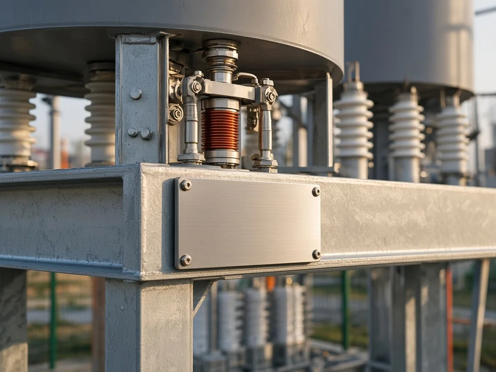
Four errors account for most of the trouble that grows out of this misunderstanding, and all four cost either results or equipment. The first has already appeared above: a capacitor placed in series with the load leaves the load conductance where it was, so the reactive current keeps flowing and the bill keeps arriving.
Ordering star-rated capacitors for a delta bank ranks second, and it shows up as heat and early failure rather than as an obvious fault. A capacitor rated for phase-to-neutral duty in a delta connection carries root-three times the voltage it was built for, while the mirror error — delta-rated units in a star bank — leaves a third of the reactive power you paid for on the table.
Thinning out a series group to save on units comes third. A group with too few units in parallel pushes the survivors past their rating the moment one unit drops out, and the failure then walks through the group instead of stopping at the first casualty.
Assuming the neutral treatment is a detail rounds off the list. Earthing a star point on a system with meaningful harmonic content invites zero-sequence and harmonic current into the bank, which is why the ungrounded neutral remains the default on many medium-voltage installations and why the protection scheme has to be chosen alongside it.
When an HYTBB Frame-Type Bank Fits the Connection You Need
Some compensation packages settle the connection question at the order stage, which suits a reader who has just worked out what they need. The HYTBB Series high-voltage reactive power compensation device in its outdoor frame-type form provides shunt capacitor compensation for substation and industrial distribution busbars, with the main wiring configuration offered as single star or double star and the matching protection method named alongside it.
Its published envelope covers 6 to 35 kV, with single capacitor units from 50 to 500 kvar and rated capacity from 150 to 10,000 kvar at 10 kV and below, or 600 to 20,000 kvar at 35 kV. Reactance ratio is chosen against the harmonic picture on the bus: roughly 0.5 to 1 percent where the concern is inrush, 6 percent where the fifth and seventh harmonics dominate, and 12 percent where the third and higher orders matter.
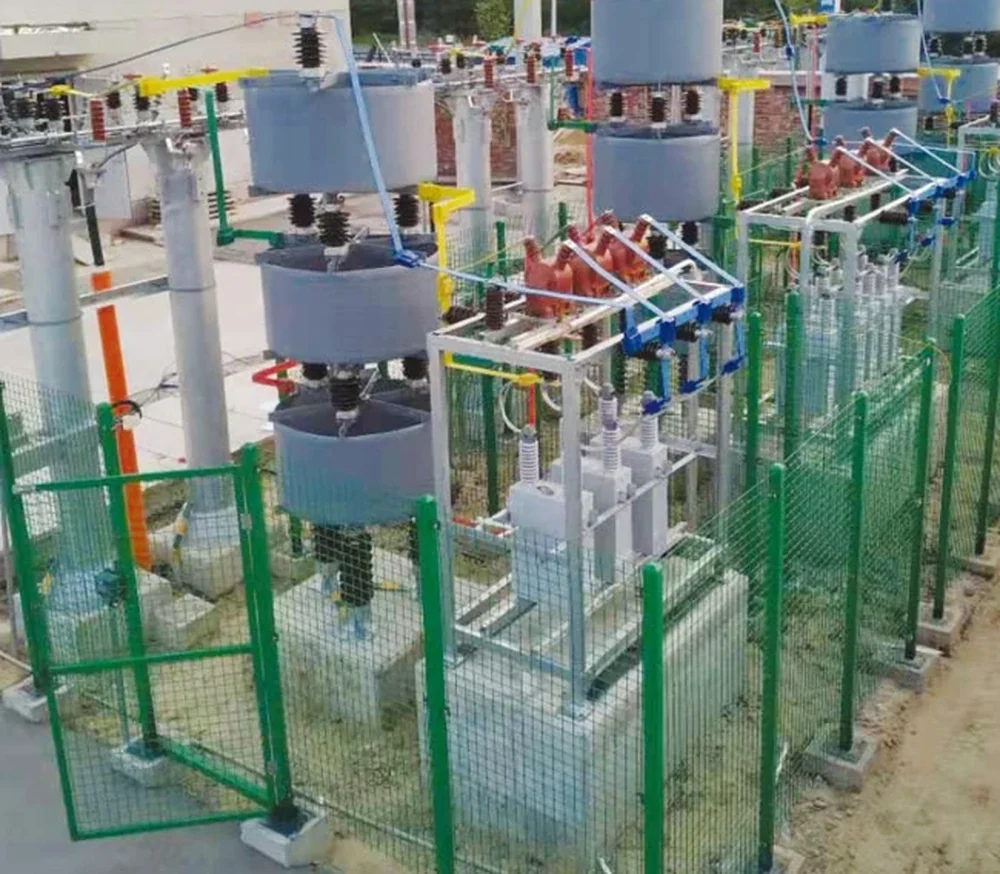
A static shunt frame like this fits steady or slowly varying reactive demand on a medium- or high-voltage bus. Rapidly fluctuating loads belong with a dynamic or converter-based package from the wider high-voltage power factor compensation range, and no shunt bank performs the line compensation that a series capacitor provides. Sending the system single-line diagram, rated voltage and required capacity lets the connection form and reactance ratio be fixed against your bus rather than guessed.
FAQ
Are the capacitors inside a single capacitor bank in series or parallel?
Both, in a deliberate pattern. Units sit side by side in parallel to build up the kvar rating, and those parallel groups stack in series so the bus voltage divides between them. Even a single capacitor unit usually contains its own internal elements in a series-parallel arrangement.
Why is a power factor capacitor bank never put in series with the load?
Because a series element changes the load circuit rather than feeding it. The total impedance stays broadly the same, so the arrangement keeps drawing similar reactive power and the correction never materialises, and the voltage appearing across a series capacitor can exceed its rating.
What is the difference between a shunt capacitor and a series capacitor?
Position and purpose. A shunt capacitor connects across the bus to inject reactive current and support voltage at that point, while a series capacitor sits in the line conductor to cancel part of the line's reactance and influence power flow along it. Long transmission lines are the usual home of the series type.
Is a delta-connected capacitor bank still used?
Yes, mostly at lower voltages, where published guidance records delta as the most common mode below 12 kV. Each capacitor in a delta bank carries a line-to-line voltage rating, and because there is only one series group per phase the bank does not rely on unbalance detection in the way a star bank does.
What does a double star capacitor bank connection give you?
Sensitive fault detection without giving up the star arrangement. The bank splits into two matched stars whose neutral points join through a current transformer, so a healthy bank leaves that transformer with nothing to read and a single failed element produces a measurable difference current straight away.
How do I tell from the nameplate whether units are in series or parallel?
Compare the capacitor voltage rating with the system voltage, then read the unit count. A rating equal to the line-to-line voltage suggests delta with one series group, while a rating near the line voltage divided by root three suggests star. The number of units per group and groups per phase tells you how kvar and voltage were shared out.
Do automatic bank steps connect in series with each other?
No. Every step forms its own parallel branch on the same busbar, each with its own switching device and usually its own fuses and reactor, and the controller simply adds or removes branches. Switching a step alters the connected kvar, not the topology of the others.
Does adding capacitors in series reduce total capacitance?
Yes. Capacitors in series combine as the reciprocal of the sum of the reciprocals, so the total is always smaller than the smallest unit in the string, and the applied voltage divides across them. Capacitors in parallel behave the other way, sharing one voltage and adding their capacitance.
References
- Series and parallel circuits — how series connection divides voltage and reduces combined capacitance, and how parallel connection shares one voltage across every component.
- Connections and composition of LV, MV and HV capacitor banks — the five three-phase connection modes, the voltage each capacitor sees, and the protection each form allows.
- Why is a capacitor bank connected in parallel and not in series? — the circuit-theory reason a power-factor bank must be a shunt branch, and where series capacitors do belong.
- Capacitor banks in substations — how a bank is assembled from single units, and the grounded star, ungrounded star, delta and double star comparison.
- Uses of capacitors in parallel and in series — practising engineers separating voltage-and-power-factor duty from transmission-line series compensation.
- Power factor — why a low power factor raises current and losses, and how stepped capacitor blocks correct it.