
 Zhejiang Hongyan Electric Co., Ltd.





































A capacitor bank is applied wherever inductive reactive demand is concentrated — at the terminals of a large steady motor, on a plant's incoming busbar, on a distribution substation busbar, part way down a long feeder, or at a generation connection point. In any application of capacitor bank compensation that position comes first, since it fixes the voltage class, decides between fixed and automatic control, and carries the constraint that can rule the bank out.
What a bank is and what sits inside it are already covered in the companion article on what capacitor banks are.
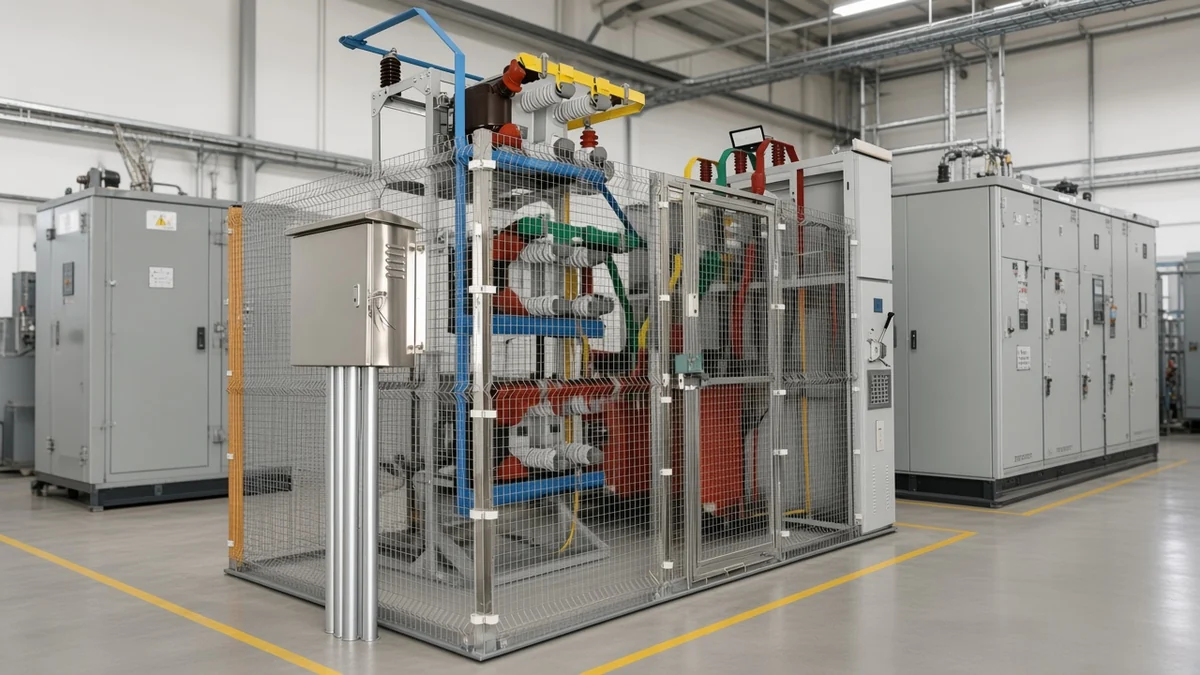
Where a Capacitor Bank Goes: Load, Plant Bus, Substation, or Feeder
Each step closer to the reactive demand unloads more of the network. The electrically strongest position is therefore the one nearest the load that creates that demand. Load size, how spread out the load is, and voltage class then push the bank back to a switchboard, a busbar or a feeder.
Reactive power, measured in kvar, is the non-working component of apparent power that magnetises motor and transformer cores — the current a plant borrows to build magnetic fields and then hands straight back. Shunt compensation hangs capacitors across the bus, which is where that current is then supplied from.
Voltage class follows the position. Primary distribution circuits sit in the medium-voltage band of roughly 600 V to 35 kV, and a large plant is often tapped straight off them, which puts its compensation on a medium-voltage bus.
Where are capacitor banks used? Seven positions cover it, and the map below sets out these capacitor bank applications in power systems with the package and the deciding limit that belong to each.
| Position | Typical voltage level | Fixed or automatic | Constraint that decides it | Typical package |
|---|---|---|---|---|
| Motor or single inductive load | The motor's own terminal voltage | Fixed | Capacitor current capped near 90 percent of motor no-load current | Small fixed unit at the terminal box |
| Plant main busbar or main switchboard | Low voltage, or medium voltage around 4,160 V in industrial systems | Automatic, stepped | Reactive demand moves through the shift | Metal-enclosed stepped bank in the switchroom |
| Distribution substation busbar | Open racks from 2,400 V upward to transmission class, typically around 4,160 V in industry | Usually switched | Load-flow and stability study has to accept the block | Open rack in the yard, or an indoor frame in the distribution room |
| Distribution feeder, part way along the run | Feeder voltage, typically 13,800 V or 33 kV | Switched with load | Far-end voltage drop at peak load | Pole-mounted or pad-mounted bank |
| Harmonic-heavy plant bus | Low voltage, or medium voltage around 4,160 V in industrial systems | Automatic, with detuned steps | Non-linear share of the load, and the measured resonance picture | Detuned steps, or a tuned filter branch |
| Commercial incoming board, and the UPS-fed IT bus beside it | Low voltage on the building side | Automatic on the building side | UPS-intensive load hands the duty to filtering and static var generation | Stepped bank on the utility and cooling load only |
| Generation or storage connection point | Whatever the connecting network uses, from medium-voltage distribution up to transmission class | Fixed base block, dynamic part elsewhere | Output falls with the square of voltage | Bank alongside dynamic compensation |
Each row has its own section below.
Motor and Process Loads: Fixed Capacitors at the Terminals, With Hard Limits
A single large induction motor on steady duty takes a fixed capacitor at its own terminals, so the reactive current never leaves the motor circuit. Two limits govern that placement: a cap on how much capacitor current the machine may carry, and a list of machine types excluded from terminal compensation outright.
Terminal compensation removes the magnetising current at its source. No cable, contactor or transformer upstream carries it any more, which suits constant-duty machines — fans, pumps, compressors — that run for hours at a stable load.
Important: the rated current of a capacitor connected directly across a motor should stay at or below about 90 percent of the motor's no-load current — and crane motors, motors that their own mechanical load can turn, and motors with electrical braking must never be compensated at the terminals.
Behind that rule sits motor self-excitation: a machine still spinning after the supply is removed can be kept excited by its own capacitors and generate voltage nobody is controlling. Oversized terminal capacitors also leave the motor overcompensated whenever it idles.
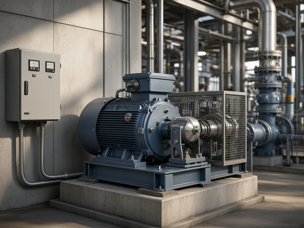
A fixed capacitor bank wired at the terminals is switched by the motor's own contactor, which means compensation appears exactly when the machine runs and disappears when it stops. Process plants with dozens of smaller motors rarely go this way, because the cost and maintenance of many small units beat the benefit of correcting each one.
The Plant Main Bus: Stepped Automatic Compensation, and What It Really Changes on the Bill
On a plant main busbar the answer is a stepped automatic bank under one power-factor controller. What it reduces is reactive and apparent power, not the real power the process consumes.
An automatic power factor correction bank is assembled from capacitor steps — a capacitor block with its own contactor — all hanging in parallel on the incoming bus. The controller reads power factor at the metering point and adds or drops steps as the shift load moves; one cabinet then covers a workshop that looks nothing like itself at night and at midday.
Because every step is its own parallel branch, a failure costs a slice of capacity while the rest of the bank keeps working, and steps can be serviced one at a time. Why those branches sit in parallel rather than in series is worked through in the companion piece on how capacitor banks are connected.
Correction subtracts kvar, which pulls apparent power and line current down. The kilowatts the process draws stay exactly where they were, as practising engineers point out whenever a current reduction gets reported as a kilowatt saving.
The tariff decides whether that pays. A kVA demand charge or a penalty for low power factor converts the released capacity into money, and a site billed on energy alone banks the gain as headroom in its transformer and cables.
Fixed or Automatic: The 15 Percent Rule and What Light Load Does to a Fixed Bank
Compensation up to about 15 percent of the supply transformer rating can stay fixed as a working rule, and anything larger should be automatically switched. The test compares the bank against the transformer feeding it, whatever the plant happens to make.
Take a 1,600 kVA supply transformer: a 200 kvar block sits comfortably inside the fixed range, while 600 kvar of correction on the same transformer belongs under a controller.
| Sizing situation | Control mode | What the control acts on | What happens when the choice is wrong |
|---|---|---|---|
| Compensation at or below about 15 percent of supply transformer rating | Fixed block, switched manually or with the load | Nothing to track; the block is in or out | Little, as long as the load really is steady |
| Compensation above that share | Automatic stepped bank | Measured power factor at the incoming metering point | Leading power factor and a rising bus voltage on quiet shifts |
| Round-the-clock constant load on one machine | Fixed block at the load | Nothing to track | Over-correction every time the machine idles |
Light load turns a fixed block into overcompensation. A block sized for the day shift stays connected through a quiet night, drives the power factor leading and lifts the bus, and that raised voltage saturates transformers, upsets generating sets and shortens capacitor life.
Cost follows the same split. A fixed block is one contactor and a set of capacitors; a stepped bank adds a controller and a switching device for every step, which is the price a plant with a moving load has to accept.
Distribution-Substation Busbars and Distribution Rooms: The Bulk Reactive Block
A bank on a distribution substation busbar is the bulk reactive block for everything the bus feeds, and it is installed only after load-flow and stability work says the bus can take it. The package is either an open rack standing in the yard or a frame inside a distribution room.
The same device is quoted at very different voltages depending on where it sits. Industrial and distribution banks are typically installed around 4,160 V, open-rack substation construction covers operating voltages from 2,400 V upward to transmission class, and the ratings in normal use vary from country to country.
From the field: substation crews skip the theory and describe what they see — put a cap in and the voltage goes up, take it out and it goes down — and how far it moves depends on where the voltage started.
Indoors the hardware changes shape. A metal-enclosed capacitor bank in a distribution room is compact, keeps heat, cold, humidity and dust off the units, and asks for less maintenance than the same capacity standing outside.
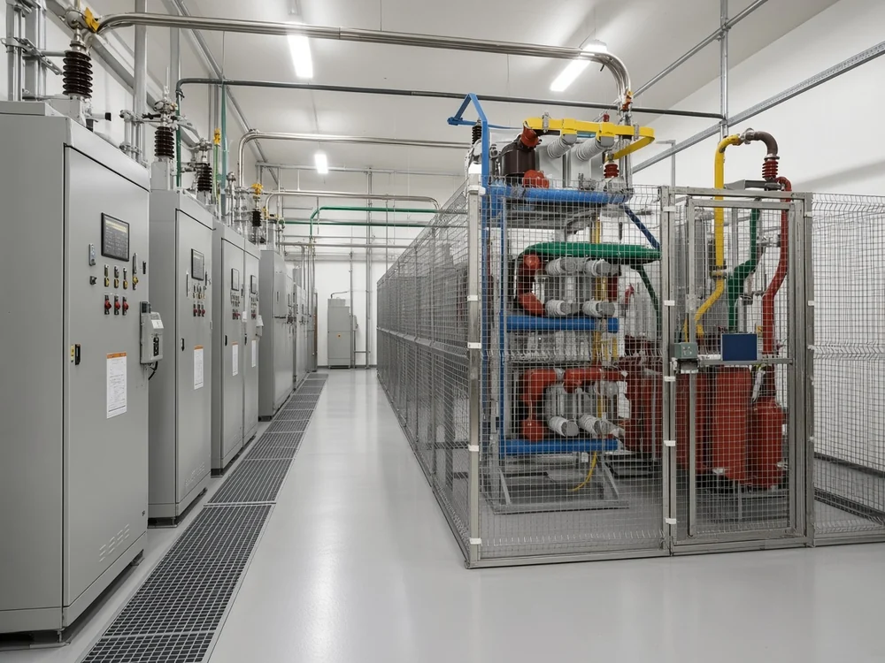
Commissioning crews meet the one hard moment when the first full block is closed onto a bus that is carrying load: the instant of closing decides how sharp that current step is, and choosing that instant is the whole subject of point-on-wave switching.
Distribution Feeders: Holding Voltage at the Far End of a Long Run
Out on a distribution feeder the bank exists to hold voltage at the far end, which is why it hangs on a pole or sits in a pad-mounted enclosure part way down the run. It follows the load, coming in when the circuit is heavily loaded and dropping out when the support is no longer needed.
Long feeders lose voltage as load accumulates along them, and the planner's remedy is either a capacitor or a voltage regulator. A bank placed part way along supplies the reactive current locally: the conductor behind it carries less of it and the tail of the circuit sits higher.
A pole-mounted capacitor bank is a three-phase set on a steel rack, built across ratings from roughly 460 V to 33 kV with unit sizes of about 300 to 3,000 kvar, and ordered either fixed or switched. Pad-mounted banks cover the 15 kV to 25 kV classes.
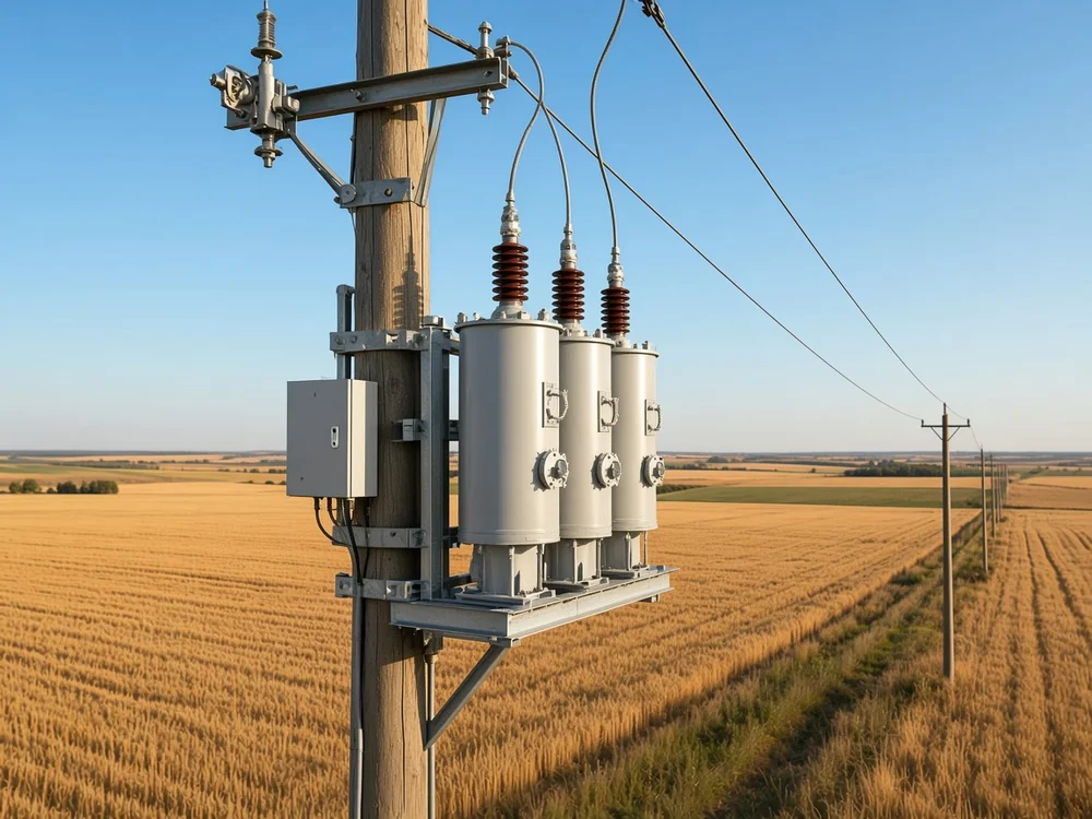
Control is the other half of feeder practice. A bank left connected overnight lifts voltage when nobody needs the support. Feeder banks are switched from voltage, current, kvar, power factor or simply the time of day, and the utility picks whichever signal matches the load pattern on that circuit.
Harmonic-Heavy Plants: Detuned Steps, Resonance Checks, and Where the SVC Takes Over
Once roughly a fifth or more of the load is variable-speed drives, rectifiers or furnaces, the steps need detuning reactors and plain capacitors stop being the right buy. Below that share the duty rating of the step climbs with the non-linear content, and the harmonic report decides which tier a bus lands in.
A capacitor bank is never a drop-in part on that kind of bus. It forms a resonant circuit with the supply transformer and the network behind it, and harmonic resonance on an order the plant already produces will amplify current instead of correcting power factor, so the harmonic picture gets measured before the steps are specified.
Non-linear load measured against transformer capacity gives the share that decides the hardware. The bands below do not overlap, and any bus up to roughly a quarter falls in one row only.
| Non-linear share of the load | Step selection |
|---|---|
| Under 10 percent | Standard-duty capacitor steps |
| 10 to under 15 percent | Heavy-duty steps |
| 15 to under 20 percent | Super-heavy-duty steps |
| A fifth (about 20 percent) or more, up to roughly a quarter | Capacitor steps with detuned reactors |
Past the top band the harmonic study decides the branch: a bus that far into converter territory is specified from its measured spectrum.
A detuned reactor in front of a step moves that branch's resonant point below the dominant harmonic, so the capacitors correct power factor without amplifying what the converters inject. Where the harmonic report shows a specific order dominating, the same idea is taken further as a tuned filter branch.
Speed of change moves the job again. A static VAR compensator takes over beside an arc furnace or a similar violently varying load: the capacitors inside it still supply the coarse reactive block, while a thyristor-controlled reactor does the fast, smooth work no contactor can repeat.
Commercial Buildings and Data Centers: Where Capacitor Steps Stop and Filters Start
A commercial building with heavy motor-driven plant is a straightforward stepped-bank case on the incoming board. Inside a UPS-intensive data hall the usual answer is active harmonic filtering and static var generation.
Chillers, lifts and pumps behind a commercial incoming board create the same kind of reactive demand a plant bus sees, and occupancy moves it through the day. Automatic control follows from that movement: the bank steps up as the building fills and drops back as it empties, holding the target power factor at both ends of the curve.
A data center UPS load behaves nothing like that. Rectifiers, server supplies and cooling drives push harmonic current onto the bus, which consumes transformer capacity and raises conductor temperature while the redundancy configuration keeps changing underneath the measurement.
For those sites, CHYN's own engineering practice distributes active harmonic filters and static var generators by bus section, which keeps redundancy and maintenance workable when the configuration changes. An active harmonic filter compensates in real time as IT and cooling load shifts, and a static var generator trims reactive power continuously.
Switched capacitors still have a place on the utility and cooling side of such a site, where the load is steady enough to be worth stepping.
Solar, Wind, and Storage Connection Points: A Base Block Plus Dynamic Support
At a generation connection point the capacitor bank carries the steady base reactive block, and the fast, changing part of the duty goes to dynamic compensation. That split keeps a mechanically switched bank useful on a site whose output never stops moving.
The point of connection is where the grid operator measures what the plant actually delivers. Its voltage is whatever the connecting network uses, from medium-voltage distribution up to transmission class, and the reactive demand seen there follows irradiance, wind and dispatch through the day.
Tip: a capacitor bank's reactive output falls with the square of the voltage, so it gives the least support at the moment the bus has already sagged — which is precisely why the fast part of the duty belongs to dynamic equipment.
At utility and new-energy nodes each element answers a different duty: high-voltage capacitor banks hold the stable base reactive power, an SVG, SVC or MSVC follows the voltage and reactive swings, and tuned filtering answers converter or network resonance where it affects harmonic behaviour.
Which Indoor Frame-Type Bank Fits the Medium-Voltage Case at 6 to 35 kV
An industrial substation or an indoor distribution room turns the map's three decisions into three ordering choices: the system voltage, fixed or automatic multi-stage switching, and detuned filtering when the harmonic report calls for it.
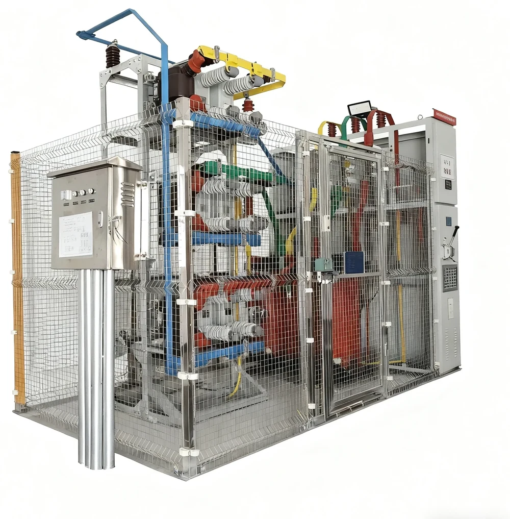
The HYTBB Series medium- and high-voltage reactive power compensation system in its indoor frame-type form is shunt compensation for that exact position, assembled from fixed or automatically switched capacitor groups inside an indoor metal frame. Its published voltage levels are 6 kV, 10 kV, 24 kV and 35 kV.
Rated capacity runs from 150 to 10,000 kvar at 10 kV and below, and from 600 to 20,000 kvar at 35 kV, with capacitor configuration and reactor detuning level matched to the site's harmonic conditions and target power factor.
It is the wrong answer for motor-terminal compensation or low-voltage switchboard work, which are other positions on the same map, and for violently swinging demand such as an arc furnace, which belongs with thyristor-based compensation. In a UPS-heavy data hall, filtering and static var generation come first.
A buyer who states the system rated voltage and frequency, the required capacity and number of banks, the harmonic report and the target power factor gets back a configuration matched to that bus, down to the detuning level. Dynamic equipment for the duties this bank does not take sits in the high-voltage power factor compensation series.
FAQ
Where is a capacitor bank actually installed in a plant — at the motor, at the switchboard, or at the substation?
The switchboard is the practical default, since the aggregate reactive demand of the site collects there and one stepped bank under a controller can follow it. Terminal capacitors win where a single machine accounts for much of the load and runs for hours at a stable duty, and the substation block is a decision for whoever owns the busbar, taken on the strength of a load-flow and stability study.
Should the bank be fixed or automatically switched?
Fixed when the compensation is small against the supply transformer and the load barely moves, automatic once it passes roughly 15 percent of that rating. On the borderline the quiet shift decides. A block the sizing test still permits can leave the site overcompensated once demand falls away overnight, and steps are the safer buy wherever that night-to-day gap is wide.
What voltage level does a capacitor bank work at?
At whatever voltage its position uses. Read the class off the bus the bank will hang on and not off the load it corrects: a medium-voltage switchroom feeding low-voltage motors takes a medium-voltage bank when the compensation sits on the incoming bus, and a low-voltage bank when it sits on the board below. The bands run from about 600 V to 35 kV across primary distribution, and indoor frames are offered at 6 kV, 10 kV, 24 kV and 35 kV.
Can I connect a capacitor straight across a motor?
Yes for a steady-duty machine sized inside the no-load current cap, and no for crane, braking and load-driven motors, which are excluded outright because a coasting machine can excite itself on its own capacitors. Those excluded motors still get compensated: their share of the reactive demand moves onto the group bank at the switchboard, where the capacitors are tied to the bus and to no single machine.
What does a capacitor bank do on a distribution feeder?
It props up the tail of the circuit at peak, and the working decision is which signal switches it. Voltage control suits a feeder whose problem is the far end, current or kvar control suits one whose problem is loading, and a clock is enough where the daily curve repeats. Two banks on the same network often behave quite differently for that reason.
Do capacitor banks lower the electricity bill?
They change what the bill is made of rather than the energy it measures. Read the invoice before deciding: a kVA or demand line and a power-factor penalty, or a recorded power factor under the utility's target, are the entries correction acts on. Where none of them appears, the kilowatt-hours are unchanged and nothing on the invoice moves.
When is a capacitor bank the wrong choice?
When the reactive demand swings faster than contactors can switch, when nobody has measured the harmonic picture on a bus full of converters, and inside UPS-intensive data halls where filters and static var generation do the work better. Each case shows itself before any study is commissioned. Flicker or a furnace-class load marks the swing problem, a converter-heavy bus with no harmonic report marks the measurement gap, and a rectifier-dominated IT bus marks the data hall.
What changes when the plant is full of drives, rectifiers or furnaces?
The steps stop being plain capacitors, and the share that picks them has to come from somewhere defensible. Read it at the bus the bank will sit on, over a window that includes the heaviest converter shift, and take it from the measured harmonic report for that bus, since connected drive rating and running load are not the same number. A bus sitting on a band edge is treated as the higher band, and the measured spectrum settles what the branch has to do from there.
References
- Power factor — why compensation is bought at all, how a controller switches capacitor blocks in steps, and why fast-changing loads outrun contactor-switched banks.
- Electric power distribution — the medium-voltage band of primary distribution, the substation busbar and feeder vocabulary, and why long feeders need capacitors or regulators.
- Static VAR compensator — where thyristor-based compensation takes over from switched capacitor banks, and how capacitors still supply the coarse block inside it.
- Why is a capacitor bank connected in parallel and not in series? — what the shunt position gives operationally, including why one failed unit costs capacity while the rest of the bank keeps working.
- In depth explanation about cap banks — substation crews describing the bus-voltage effect of switching a bank in and out.
- Does power factor correction reduce kW consumption on a plant? — practising engineers separating kvar and kVA from the real power a plant consumes.