
 Zhejiang Hongyan Electric Co., Ltd.





































A shunt capacitor bank is used to supply leading reactive power next to inductive loads so a plant can raise power factor, support voltage, and cut upstream current and losses—that is what is a capacitor bank used for on an industrial bus. The same shunt capacitor bank job shows up at a motor, an MCC, or a substation bus whenever magnetizing current would otherwise travel the whole feeder. This page maps those jobs, then shows when what is capacitor bank used for in a drive-heavy plant is actually a tuned filter-compensation package rather than a plain capacitor lineup.
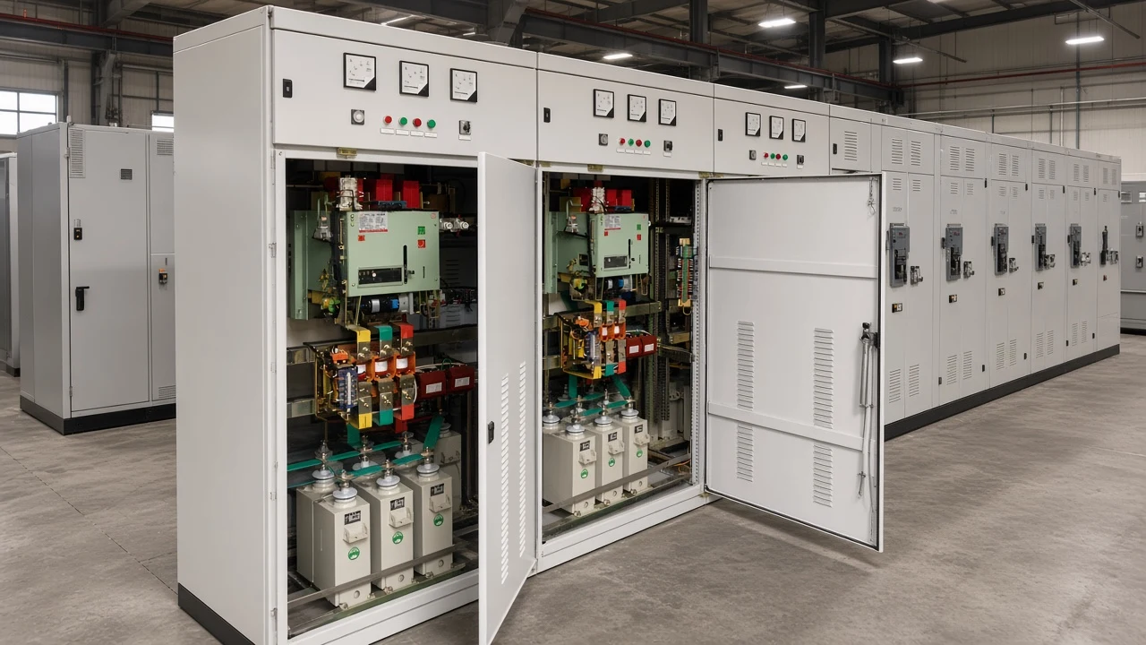
The jobs a shunt capacitor bank is used for
A shunt bank is used to supply leading kvar locally for power factor, voltage support, and lower upstream current—not to compensate a line the way a series capacitor does.
IEEE’s technology note puts the assembly in those terms: grouped capacitor units connected so they can deliver a rated reactive output, then placed on the system to supply reactive power locally. That local supply is the use. The outcomes—better voltage profiles, less reactive current in upstream circuits, and better industrial or commercial power factor—are the same job seen from three meters.
A series capacitor is used for a different job. It sits in the line and offsets circuit inductive reactance, rather than changing the load’s power factor at a bus. Keep this page on the shunt case.
| Job | What the bank is used to do | What the plant notices |
|---|---|---|
| Power factor | Offset lagging kvar from motors and transformers | Higher PF at the meter; fewer demand-charge fights |
| Voltage support | Cut reactive flow through feeder reactance | Firmer bus or end-of-feeder voltage |
| Current and I²R | Lower apparent power for the same kilowatts | Cooler cables and transformers |
| Capacity release | Free kVA that reactive current was occupying | Headroom on the house transformer |
| Filter bank | Give selected harmonics a low-impedance path while still supplying kvar | Cleaner current when the load is nonlinear |
Composition and switching hardware live on what capacitor banks are. Mechanism language lives on what capacitor banks do.
Used for power factor correction on inductive plant loads
Plants use a bank so motors and transformers stop importing lagging kvar through the utility meter and the house transformer.
Most industrial current lags voltage because induction machines and transformers need magnetizing current. That reactive power (kvar) does little shaft work, yet it still counts in apparent power. Power factor is the professional name for P/S; in plain language it is how much of the amperes are doing useful work.
A shunt bank draws leading current. At the connection point the leading and lagging components partly cancel, so the source sees a smaller net Q. That is classic power factor correction: the process kilowatts can stay the same while the kVA the utility and the transformer must carry falls.
Plant electricians on Physics Forums describe the same industrial pattern: banks go in after the transformer to hold lagging plant power factor near unity, and fixed steps that stay on when motors drop off leave the bus leading. Their practical fix is to stage capacitance with the load—or move correction closer to the motors—so the compensation tool tracks inductive demand instead of fighting it.
How-to sizing and controller steps belong on the live capacitor bank for power factor correction page. Switching and kvar staging belong on capacitor banks for reactive power compensation.
Used for voltage support when reactive flow sags the bus
It is used to cancel reactive flow so the Q·X drop shrinks and the bus sits closer to the intended voltage.
On many industrial and distribution feeders, reactance dominates resistance. Approximate drop behaves like ΔV ≈ (P·R + Q·X) / V, so a large lagging Q still sags the bus even when real power is modest. Supplying that Q at the load is voltage support: the feeder no longer has to carry the magnetizing current that was pulling the voltage down.
IEEE’s note adds a sizing intuition used by utilities: adding Q kilovars on a bus with short-circuit level S raises voltage on the order of Q/S per unit. That is why a large always-on bank on a weak bus can lift voltage more than the PF story suggested.
The same physics runs backward at night. A fixed bank that was right at peak load can push voltage high when motors are off. Switched banks exist so the voltage-support job can be turned down with the load.
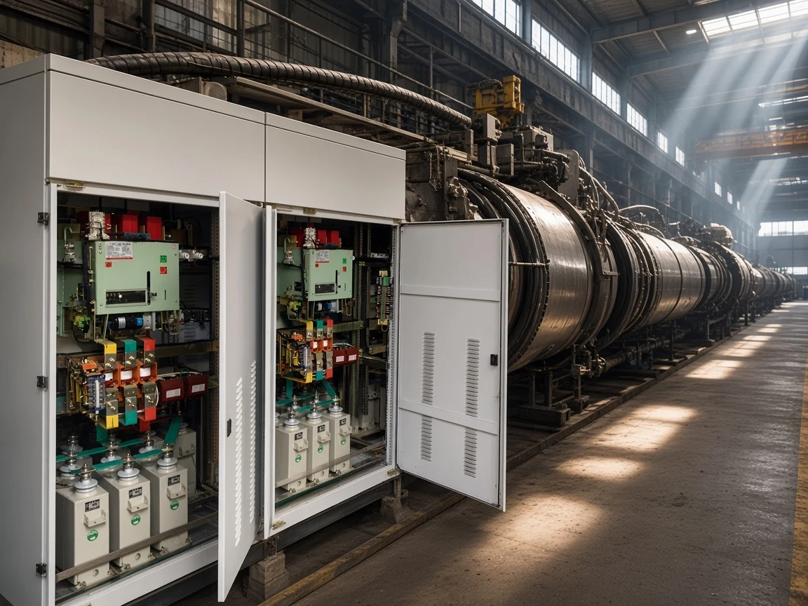
Used to cut current, I²R losses, and wasted kVA
The same kvar job lowers apparent power, so line current falls and heating falls faster than current.
Three-phase current tracks apparent power, not kilowatts: I = P / (√3 × V × PF). Raise power factor and I drops even if the process still draws the same P. Resistive heating in cables and transformer windings scales with I²R, so a modest amp reduction becomes a larger loss reduction.
Independent teaching notes make the arithmetic visible with the same three-phase current formula.
A 500 kW load at 480 V, moving from 0.75 to 0.95 lagging, needs about 277 kvar (from Qc = P(tanφ₁ − tanφ₂)). Apparent power falls from about 667 kVA to 526 kVA.
Line current falls from about 802 A to 633 A—about 21%—and I²R on that path falls by nearly 38%. Treat those figures as classroom arithmetic from the formulas above, not a CHYN factory test. Read the same current-and-loss consequences on Electrical Technology’s capacitor-bank applications note.
| Quantity | Before (PF 0.75) | After (PF 0.95) |
|---|---|---|
| Real load | 500 kW | 500 kW |
| Apparent power | about 667 kVA | about 526 kVA |
| Line current at 480 V | about 802 A | about 633 A |
| Relative I²R on that path | 100% | about 62% |
The bank does not replace process kilowatt-hours. It removes unnecessary reactive amperes so less real power is wasted as heat upstream of the load. That is also how transformer capacity is released: the same kW needs fewer kVA of apparent power (kVA).
Tip: Independent engineering notes say the benefit is largest when correction sits near the inductive load (local or de-centralized banks), because everything upstream of that point sees the smaller current. Read the placement methods on Electrical Technology’s capacitor-bank applications note.
Internal wiring and charge/discharge timing are covered on how capacitor banks work.
Industrial situations that call for those jobs
The jobs appear on motor-heavy buses, weak feeders, and substations that must hold PF and voltage as load changes.
A machine shop or process line with many induction motors uses the bank first for power factor correction at the MCC or main LV bus. The plant notices the meter and the transformer temperature before it notices a physics lecture.
A long feeder or a soft utility connection uses the same hardware for voltage support. Motors still start, lights stay in band, and relays are less likely to drop on a sag that was mostly reactive drop.
A utility or plant substation uses shunt banks for the same outcomes independent primers list: power-factor correction, voltage regulation, lower cable and transformer heating, and headroom on apparent power. Electrical Technology’s capacitor-bank applications note frames those jobs together with placement choices when nonlinear loads share the bus. Plants that keep a fixed bank on after process motors drop off still have to decide whether the remaining steps still match the lighter load—the same light-load leading-PF problem raised on Physics Forums.
| Situation | Primary job | Watch-out |
|---|---|---|
| Motor-heavy MCC | Power factor at the plant meter | Load swings; prefer switched steps |
| Long or weak feeder | Voltage support | Light-load overvoltage if the bank stays on |
| Transformer near kVA limit | Current / capacity release | Confirm the limit is reactive, not real kW |
| Drive- or furnace-heavy bus | PF plus a harmonic filter bank | Plain capacitors can resonate |
A location-by-location catalog of poles, pads, and EHV racks already lives on application of capacitor bank. Stay here for the job, not the map.
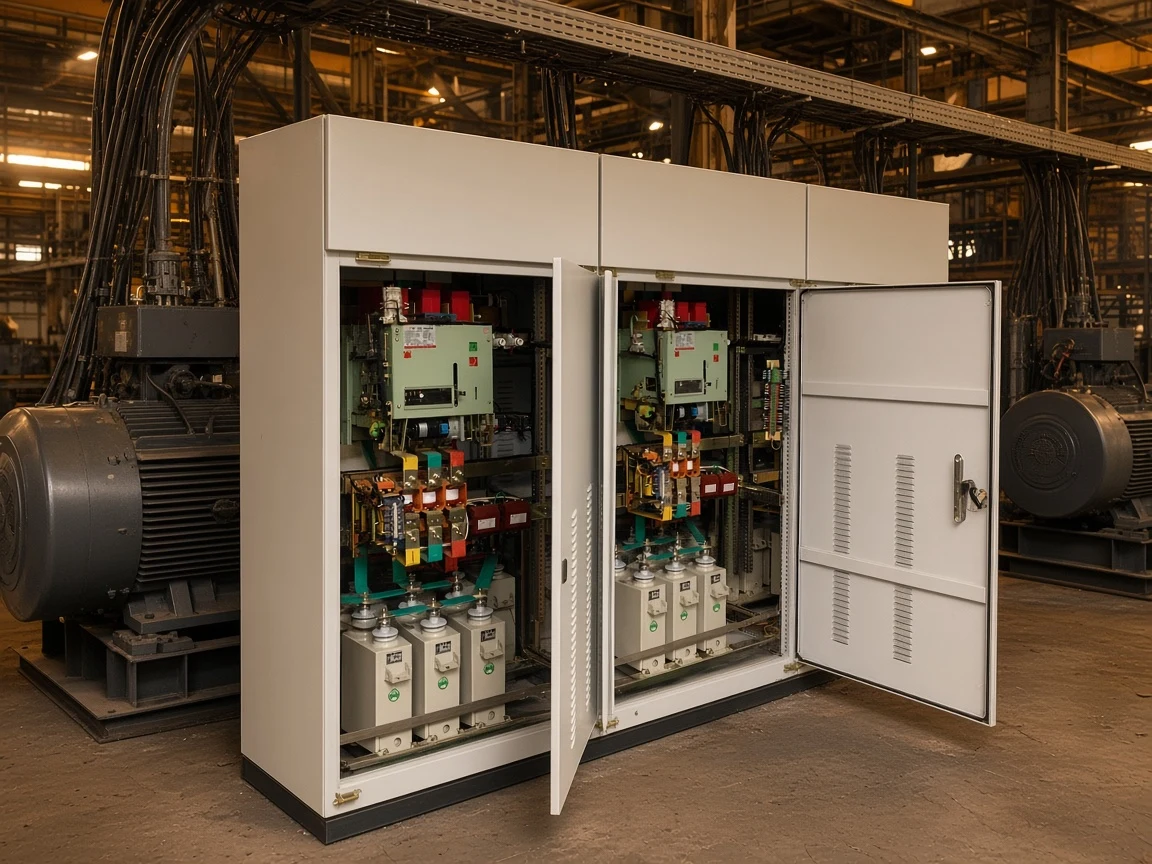
When to choose a filter-compensation package for the same job
Choose a tuned filter-compensation package when the PF job shares the bus with characteristic harmonics.
Power-quality practitioners on Physics Forums still start with shunt capacitor banks for lagging fundamental current. They also warn that a straight capacitor bank on a harmonic-rich bus can resonate with source inductance near a characteristic harmonic, so the ideal “close to the load” placement can be the wrong engineering answer. A bank that only sees the fundamental cannot correct distortion power factor, and an undamped resonant path can make voltage and current distortion worse.
Important: If VFDs, rectifiers, or furnaces already distort the current, treat a plain shunt bank as incomplete. IEEE’s topic page lists filter banks as their own use case for arc-furnace and drive-heavy installations; read that applications list on Capacitor Banks | IEEE Technology Navigator.
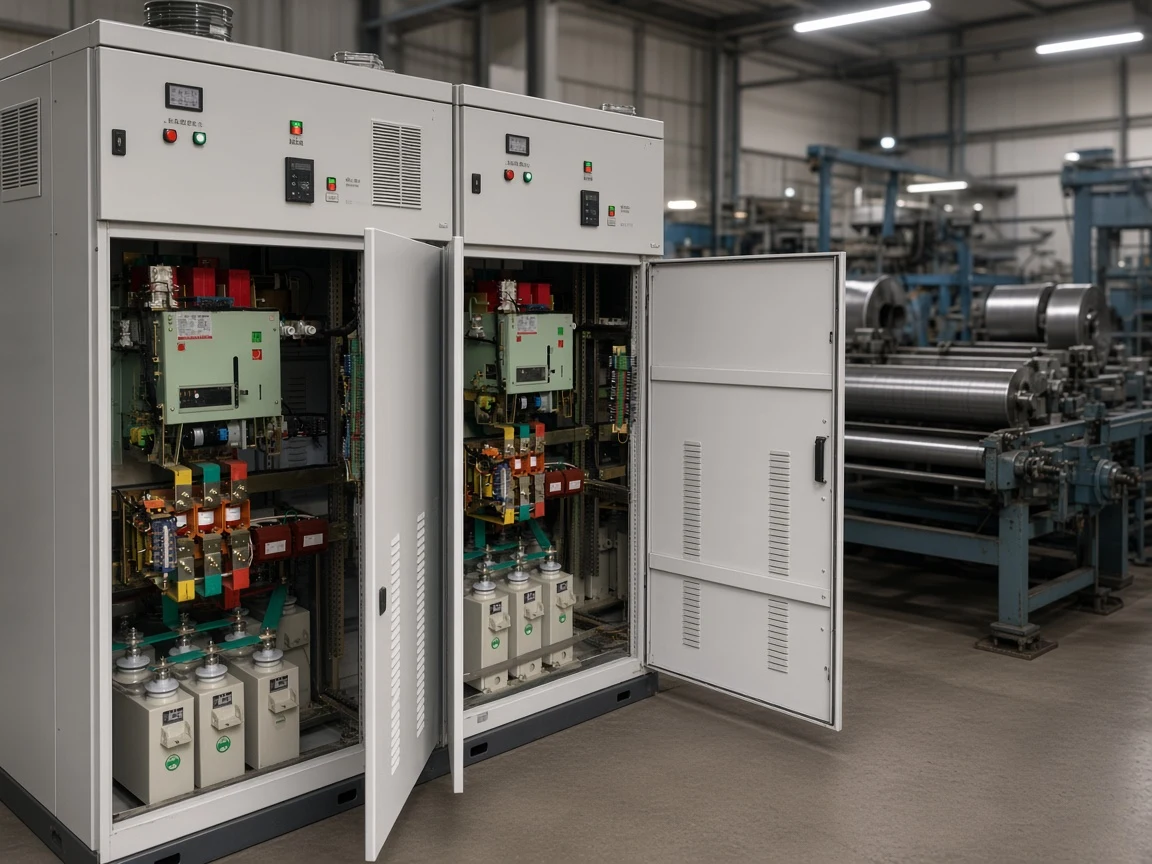
The HYFC Series Low-Voltage Static Passive Harmonic Filter & Compensation Device is built for that combined job. It is an economical tuning-type filtering and reactive power compensation cabinet: filter reactors, filter capacitors, filter resistors, contactors, and circuit breakers arranged as tuned LC branches. At the resonant frequency, where capacitive and inductive reactance of a branch match, the branch is a low-impedance path for targeted harmonic orders.
Live product copy says those branches are used to absorb characteristic harmonics such as the 5th, 7th, 11th, and others from non-linear loads, while the same equipment still provides reactive compensation to raise power factor and reduce line losses. Integrated protection on the page includes over-current, over-voltage, under-voltage, capacitor protection, and system fault indication. Each tuned branch is described as designed by computer simulation against site load characteristics.
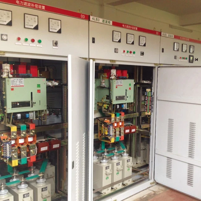
Published ratings on that page cover rated voltage 220 V to 1000 V (−15% to +10%), rated frequency 50 hertz (±1 Hz), operating temperature −25 °C to +40 °C, and altitude up to 2000 m. Order inputs include system voltage, the site harmonic spectrum, filtering capacity, and reactive compensation capacity. That is a capacitor-and-filter package for the “used for PF plus harmonics” job, not a medium-voltage HYTBB frame lineup.
Do not choose HYFC when the load is essentially linear and the only need is fundamental kvar on an HV outdoor rack. Those readers should stay on the high-voltage power factor compensation series hub and the live PF or RPC articles. Motor-terminal or always-on fixed steps have a further plant limit: when the process is down, leftover capacitance can leave a leading power factor and the light-load overvoltage problem already noted above.
FAQ
What is a capacitor bank used for in a plant?
It is used to supply leading reactive power next to inductive equipment so the plant can correct power factor, support voltage, and reduce upstream current and I²R heating. Those are one physical job seen on three different meters.
Is a capacitor bank only used for power factor correction?
No. Power factor is the usual industrial reason, but the same local kvar is also used for voltage support and for freeing transformer and feeder kVA. Series line compensation is a separate job.
Does using a capacitor bank reduce current and losses?
Yes, for the path upstream of the bank. The 500 kW / 480 V classroom arithmetic above shows about a 21% current cut and nearly 38% I²R cut when PF moves from 0.75 to 0.95. The machines still consume their real kilowatts.
Why does a capacitor bank raise voltage at the bus?
Because less lagging Q flows through feeder reactance, the Q·X part of voltage drop shrinks. Added Q relative to short-circuit level also lifts the bus on the order of Q/S per unit, which is why oversizing at light load can overshoot.
Should the bank sit at the motor, the MCC, or the utility meter?
The job helps everything upstream of the connection, so closer to the inductive load usually frees more cable and transformer capacity. Harmonics, cost, and switching can still push the bank to the main bus or the substation.
Can a capacitor bank be used for harmonics?
A plain shunt bank is used for fundamental kvar. When characteristic harmonics are already on the bus, the related use is a harmonic filter bank—tuned LC branches that still supply reactive power, which is the HYFC role.
What if the bank is too large for the load?
Light-load overvoltage and a leading power factor are the usual results. Switch steps off—or stage them with the motors—when the process is down.
Is a capacitor bank used like a battery to store surplus energy?
Not in the shunt power-system sense this article covers. The everyday industrial use is reactive support, not bulk energy storage for later kilowatt-hours.
References
- IEEE Technology Navigator topic page on capacitor banks in power systems
- Electrical Technology on capacitor bank characteristics and applications
- Tutorials Point primer: What is a Capacitor Bank and why is it used?
- Physics Forums discussion: How to correct for a leading power factor (kVArh)
- Physics Forums discussion: Odd harmonics in power system reduction