
 Zhejiang Hongyan Electric Co., Ltd.





































How do capacitor banks work? A shunt capacitor bank connects capacitive reactance in parallel with inductive loads so the bank’s leading current offsets lagging magnetizing current; upstream apparent power and line current fall, while bank kvar output follows the square of applied voltage.
This guide walks the mechanism in order: how leading kvar appears, why feeder current drops, the voltage-squared limit, fixed vs switched capacitor bank behavior, what related pages already own, and when a dynamic TCR path belongs in the conversation.
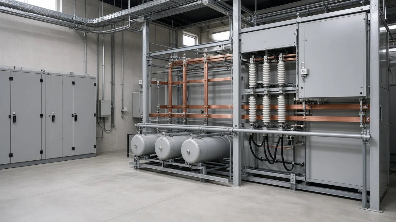
How a Shunt Capacitor Bank Supplies Leading kvar
The bank injects leading reactive power (leading kvar) in parallel with lagging inductive loads so the two reactive currents partially cancel at the point of connection.
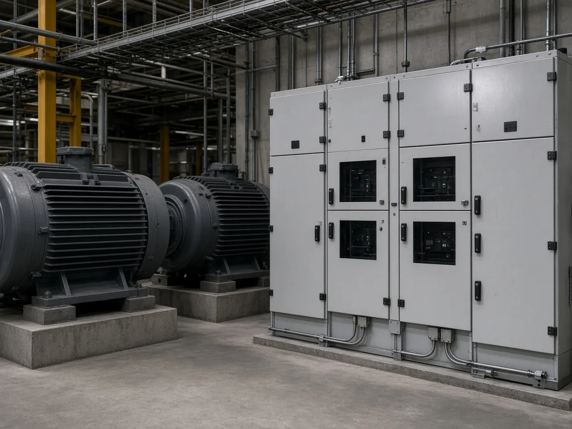
The shunt connection places the bank across the supply—phase to phase or phase to neutral—beside motors, transformers, and other inductive equipment. Ideal capacitor current leads terminal voltage by about ninety degrees. That leading reactive power offsets the lagging reactive current those loads demand, which is the core of shunt power-factor correction (IEEE Technology Navigator — Shunt Power Capacitors; EEP — capacitive reactive compensation with shunt banks).
| Mechanism step | What happens |
|---|---|
| Inductive load online | Current lags voltage; the source must carry lagging kvar |
| Shunt bank connected | Capacitors draw leading current at the same bus |
| Net reactive current | Leading and lagging shares cancel in part |
| Upstream view | The feeder sees a smaller reactive component and higher power factor |
Think of reactive power as the magnetizing “share” that does not turn a shaft but still occupies conductors. The bank supplies that share locally so the utility or upstream transformer need not carry as much of it (GIEE — capacitor banks in power systems).
For a short definition of the equipment object itself, see what are capacitor banks. For the jobs and outcomes buyers expect after installation, see what do capacitor banks do.
Why Line Current Falls When the Bank Is Online
For the same real power (kW), raising power factor shortens apparent power (kVA), so three-phase line current falls in proportion.
Power factor is real power divided by apparent power. When lagging kvar shrinks, the hypotenuse of the power triangle shortens even though useful work stays the same (Wikipedia — Power factor; GIEE). Apparent power / line current therefore move together: line current tracks apparent power, not kilowatts alone, which is why a correctly applied bank cools feeders and frees transformer capacity.
An independent worked example on a 500 kW load moving from 0.75 to 0.95 lagging shows line current falling about twenty-one percent and I²R losses falling nearly thirty-eight percent because loss scales with the square of current (GIEE Example 1). Treat those figures as an attributed illustration, not a measurement from a CHYN plant.
| Quantity | Before (example) | After (example) |
|---|---|---|
| Real power | 500 kW | 500 kW |
| Power factor | 0.75 lag | 0.95 lag |
| Apparent power | ~667 kVA | ~526 kVA |
| Line current (480 V class example) | ~802 A | ~633 A |
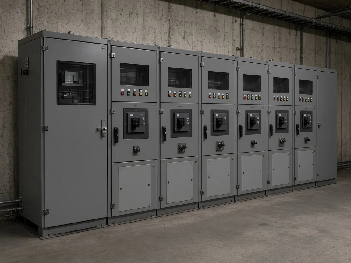
That current cut is the practical reason procurement teams care about the mechanism, not only about a tariff label.
The Voltage-Squared Limit on Bank kvar Output
Capacitive reactive output of a shunt bank scales with the square of applied voltage over the capacitive reactance—so a soft bus delivers less kvar than the nameplate suggests at rated volts.
Community and textbook language state the same identity: reactive power for the capacitive branch is proportional to V²/X (Physics Forums — reactive power / shunt vs series). If voltage sags on a long feeder, available leading kvar falls quickly. If voltage rises at light load with excess capacitance online, both kvar output and voltage support push in the same direction—another reason overcorrection matters.
Designers therefore size and locate banks with the expected operating voltage band in mind, not only with a spreadsheet PF target. High-voltage capacitor bank design covers those rating and layout checks in a separate package.
Fixed Versus Switched Capacitor Bank Behavior
A fixed capacitor bank keeps a constant kvar block online whenever its feeder is live; a switched or automatic bank adds and removes steps so compensation tracks load.
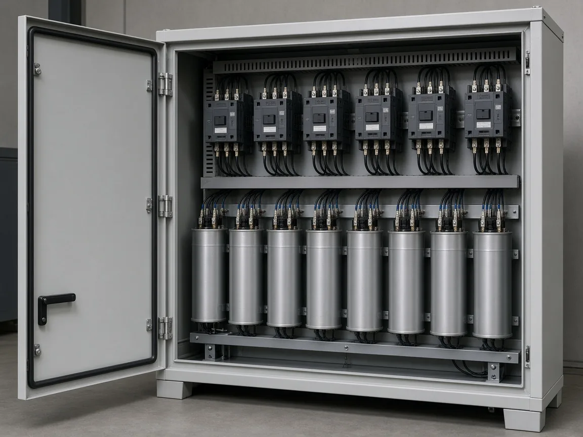
IEEE notes that automated switched banks typically switch in during heavy load and switch out at light load to avoid leading power factor and the resulting voltage rise (IEEE — Shunt Power Capacitors). Controllers, contactors, and staged racks are how plants implement that tracking.
From the field: Operators have asked what happens when motors idle overnight while a static bank stays fully online—the power factor can swing leading. Practitioners warn that excess capacitance can stir local voltage complaints and large inrush on the next switching event, even when the monthly tariff mainly penalizes lagging PF (Physics Forums — leading PF at night).
| Behavior | Fixed bank | Switched / automatic bank |
|---|---|---|
| kvar online | Constant while energized | Steps follow measured demand |
| Best fit | Steady process load | Plants that idle large motors |
| Light-load risk | Leading PF / voltage rise if oversized | Lower if the controller sheds stages |
| Complexity | Simple | Needs sensing, interlocking, discharge timing |
Field discussions of substation practice make the same split: some banks stay on for voltage support; others switch through the day as load and voltage move.
What This Mechanism Explanation Does Not Cover
This page owns shunt-bank physics; it does not re-own definition essays, outcome lists, series-line design, or switching-transient depth.
A series capacitor primarily offsets line inductive reactance rather than supplying bus kvar in parallel—the shunt path is the usual industrial PF tool (Physics Forums — shunt vs series). Energizing any bank can still create inrush and stress breakers; treat that as a boundary note here, not a full switching guide (IEEE — Capacitor Banks).
Plain capacitor stages also do not cancel harmonic current by themselves. When nonlinear loads dominate, filter branches or a dynamic compensator become part of the conversation under the High Voltage Power Factor Compensation Series hub.
Product recommendation: When HYSVC Fits Fast Load Swings
When load vars swing faster than contactor steps can track—arc furnaces, rolling mills, mining impact loads—a TCR paired with fixed capacitor and filter branches extends the shunt idea into continuous regulation.
Recommended product / solution: HYSVC Series High Voltage Dynamic Reactive Power Compensation and Filtering Device
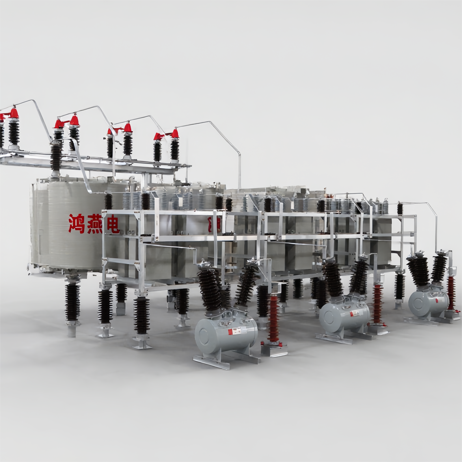
The live HYSVC page describes a thyristor-controlled reactor as a TCR / SVC (HYSVC) package working with fixed capacitor branches and harmonic filter branches. Stated scope includes system voltage 6–35 kV, response time under 10 ms, trigger-angle control accuracy of ±0.1°, and filtering of the 2nd through 13th harmonics, with centralized bus or distributed near-load placement.
Use HYSVC when the mechanism above is correct but stepped shunt banks alone cannot hold bus voltage and harmonics under rapid swings. Prefer a correctly sized fixed or switched shunt bank when the plant load is steady and the harmonic environment is mild.
FAQ
How do capacitor banks work in simple terms?
They sit in parallel with inductive loads and inject leading current so lagging magnetizing current is cancelled locally, which raises power factor and usually lowers feeder current.
Why does a capacitor bank reduce line current?
Apparent power falls when reactive demand falls. Line current follows apparent power for a given voltage, so the same kilowatt load draws fewer amperes after correction.
What is the difference between a fixed and a switched capacitor bank?
A fixed bank keeps constant kvar online. A switched or automatic bank adds and removes stages so compensation follows the load and avoids light-load overcorrection.
Does capacitor bank kvar change with voltage?
Yes. Capacitive reactive output scales with the square of applied voltage, so a weak or sagging bus delivers less kvar than the rated nameplate implies.
Can a fixed bank create leading power factor at night?
Yes. If motors idle while the bank stays fully online, excess capacitance can push the metered PF leading and raise voltage or switching stress concerns.
Are shunt and series capacitor banks the same?
No. Shunt banks supply vars in parallel for PF and voltage support. Series banks mainly offset line reactance on long circuits.
Do capacitor banks fix harmonics by themselves?
Not by themselves. Plain shunt stages correct displacement kvar; harmonic-rich plants need detuning, filter branches, or dynamic devices such as TCR-based systems.
When is a dynamic TCR plus capacitor system considered?
When reactive demand and harmonics swing too fast for stepped contactors—typical of furnaces, mills, and similar impact loads—and the project needs continuous regulation on a medium-voltage bus.
References
- EEP — Providing capacitive reactive compensation with shunt capacitor banks
- IEEE Technology Navigator — Capacitor Banks
- IEEE Technology Navigator — Shunt Power Capacitors
- GIEE — Capacitor Banks in Power Systems
- Wikipedia — Power factor
- Physics Forums — Leading power factor at night / overcorrected banks
- Physics Forums — Shunt vs series capacitors and Q ∝ V²/X