
 Zhejiang Hongyan Electric Co., Ltd.





































High voltage capacitor bank design freezes HV and MV bus voltage, switching duty, reactor need, discharge timing, enclosure form, and unbalance checks before kvar is treated as an orderable figure.
A general design-package walkthrough already lives on the live capacitor bank design page; this article stays on the HV/MV checks that decide whether a bank is safe to order and reclose. How capacitor banks work at a basic level is a separate primer, so the sections below assume you already know a shunt bank supplies leading vars.
You will walk voltage-class inputs, shunt capacitor bank switching duty, reactor and discharge checks, capacitor bank unbalance protection, outdoor versus indoor form, and when a medium-voltage thyristor-switched package fits fast industrial loads.
HV/MV Design Inputs You Must Freeze First
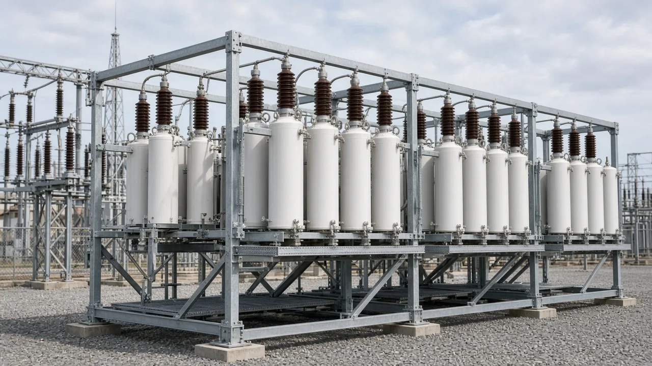
Freeze the corrected-bus voltage and the maximum operating voltage, the reactive load profile, short-circuit context, and harmonic cues before you lock kvar.
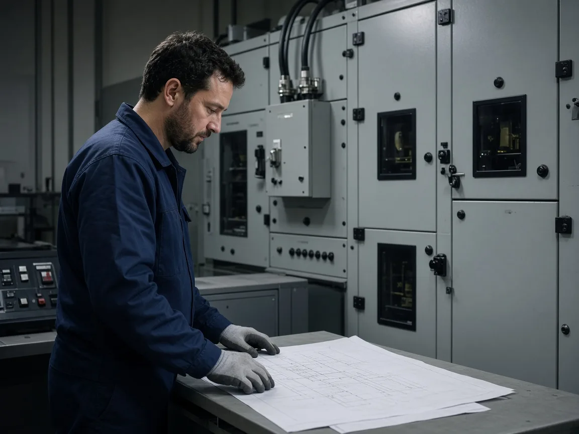
Bus voltage class is the first order field. Utility HV application guidance commonly rates banks at least five percent above nominal bus voltage, or above the highest anticipated operating voltage if that is higher. That margin is a design input, not a certification claim for any one supplier.
On an industrial medium-voltage bus in the published six- or ten-kilovolt class, write the actual corrected-bus voltage on the single-line before anyone counts series groups. Record the daily reactive shape next.
A hoist or crusher that swings every few minutes is a different bank problem than a steady plant base load. Short-circuit strength at the connection point and any measured harmonic spectrum decide whether a plain bank is even eligible.
Tip: Name those inputs on the enquiry before printing a kvar figure that only came from nameplate motors. - Research decision against AIO sizing formulas; freeze measured inputs first (PJM voltage-margin practice)
| Design input | Why it freezes the design | What to record |
|---|---|---|
| Corrected-bus voltage and max operating voltage | Sets unit series count and insulation class | Nominal kV, maximum pu or kV seen in service |
| Reactive load profile | Chooses fixed, stepped, or fast dynamic switching | Heavy/light load Q, cycle time, night load |
| Fault level / short-circuit context | Sizes inrush duty and switchgear interface | Three-phase fault level at the bank bus |
| Harmonic spectrum or nonlinear load share | Decides plain bank vs detuned reactor capacitor bank | Dominant orders, drives/furnaces present |
| Site environment | Chooses open-rack outdoor vs enclosed/indoor | Indoor/outdoor, pollution, access for cans |
Switching Duty: Fixed, Stepped, or Thyristor-Dynamic
Match the switching method to how fast reactive demand moves-fixed for steady loads, multi-stage or thyristor-dynamic when the load swings.
A CIGRE survey of capacitor switching practice found that more than half of responding utilities switch banks at least once per day for voltage and VAR support. That rate already treats shunt capacitor bank switching duty as a first-class design input, not an afterthought.
Fixed banks still fit when reactive demand is nearly constant. They fail when motors drop overnight and the bank stays online.
From the field: On a Physics Forums design thread, an engineer warned that if capacitors are fixed and the load is too low, "you will then have leading PF-which causes its own problems," and the case needs a professionally engineered system. - Physics Forums thread on fixed-bank leading power factor risk
Stepped contactor or breaker banks track slower daily shapes. A thyristor-switched capacitor (TSC) fits when the plant needs near-cycle response on a fluctuating MV bus-rolling mills, hoists, crushers-without waiting for a mechanical step.
Switching duty also sets whether you need controlled closing, pre-insertion resistors, or semiconductor switching to manage inrush and restrike risk over years of operations.
Reactor and Detune Checks for HV/MV Banks
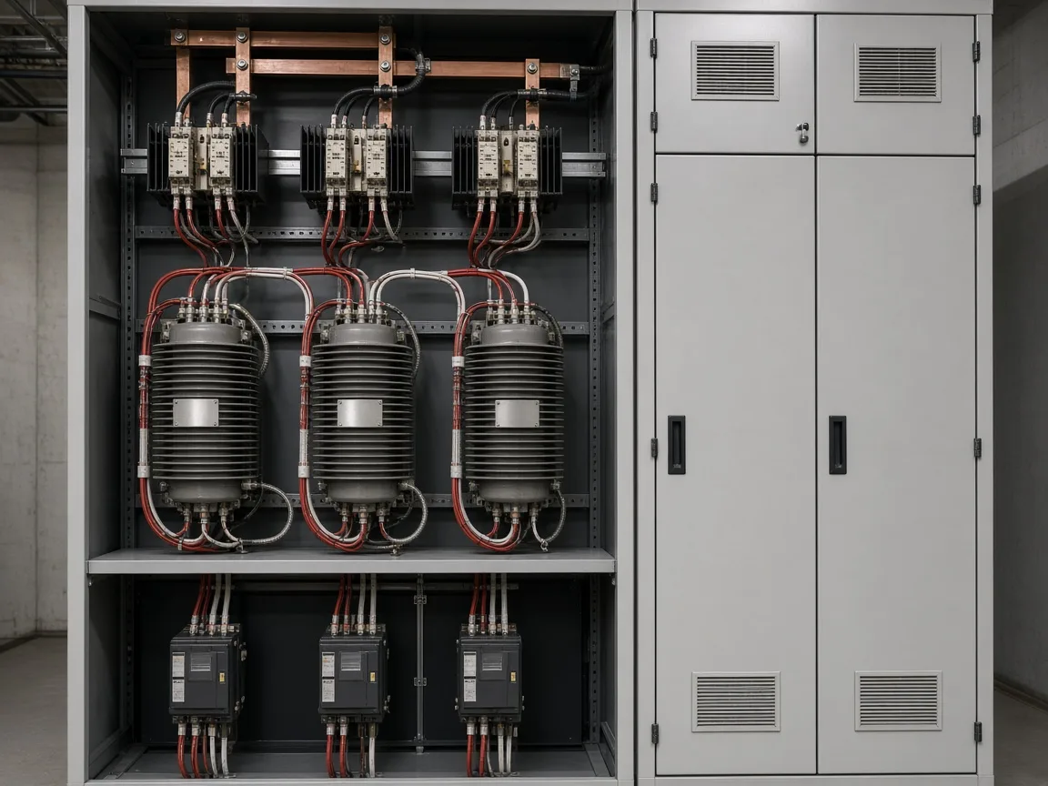
Require a detuning / damping reactor when harmonics or multi-bank back-to-back switching duty are present.
Svenska kraftnat's shunt-bank guideline requires damping reactors when more than one shunt capacitor bank connects in the same substation, sized so back-to-back switching inrush stays within the referenced limits. Even a single industrial bank can need a series reactor when drives or furnaces inject harmonics that would otherwise resonate with the bank.
The reactor percentage is an order field, not a decoration. On a published 6/10 kV thyristor-switched family, reactor tuning of 6% or 13% appears as selectable detune options beside the bank size ladder.
Choose the percentage from harmonic study results, not from habit. If a second bank will share the same station later, design the first bank as if back-to-back switching already exists. A detuned reactor capacitor bank is the usual order language when those checks fail a plain bank.
Discharge Timing and Reclose Checks
Do not reclose until residual and trapped charge have decayed through the designed discharge path.
Independent technical guidance describes unit discharge resistors that reduce residual voltage to 50 V within five minutes. Transmission application guidance likewise tells operators not to reclose until trapped charge has decayed to an acceptable level, commonly about five minutes.
Those timings are practice cues for the design package. They are not a substitute for the manufacturer's discharge data on the cans you buy.
Important: A bank that trips on unbalance or overvoltage is still charged. Closing again before the discharge wait finishes stresses the switching device and the remaining units. - PJM shunt-capacitor guideline trapped-charge reclose wait; EEP unit discharge timing guidance
Write the discharge expectation and the anti-reclose interlock into the control narrative. Maintenance procedures should assume residual voltage until the designed bleed-down time has passed.
Fuse, Unbalance, and Overvoltage Checks
Name the fuse architecture and capacitor bank unbalance protection so one failed unit or fuse group does not overstress the rest of the bank.
Externally fused, internally fused, and fuseless constructions change how a failed element presents itself to protection. External fuses clear a whole can and give a visual cue; internal fuses clear elements inside the can; fuseless strings rely on welded shorts and unbalance sensing as successive elements fail.
The design package must state which architecture is ordered, because the unbalance signal level and the spare strategy change with it. Bank stability checks commonly keep remaining units within about 110% of rated voltage after a single fuse operation.
If that threshold would be exceeded, the bank should leave service rather than run degraded. Overcurrent, overvoltage, and earth-fault functions still belong on the bay; unbalance is not a substitute for them.
From the field: A substation switching crew described a one-hundred-thirty-eight-kilovolt shunt bank where an entire parallel group of eleven capacitors blew their fuses while other series groups on the same phase looked normal. - Physics Forums thread on substation capacitor bank fuse-group failure
After testing "healthy" cans and refusing the group, all eleven fuses blew again on re-energization. That pattern is why group-level unbalance trips and series-group reviews belong in the design check, not only single-can spares.
Outdoor Versus Indoor Enclosure Checks
Site environment and access decide open-rack outdoor versus enclosed or indoor packages.
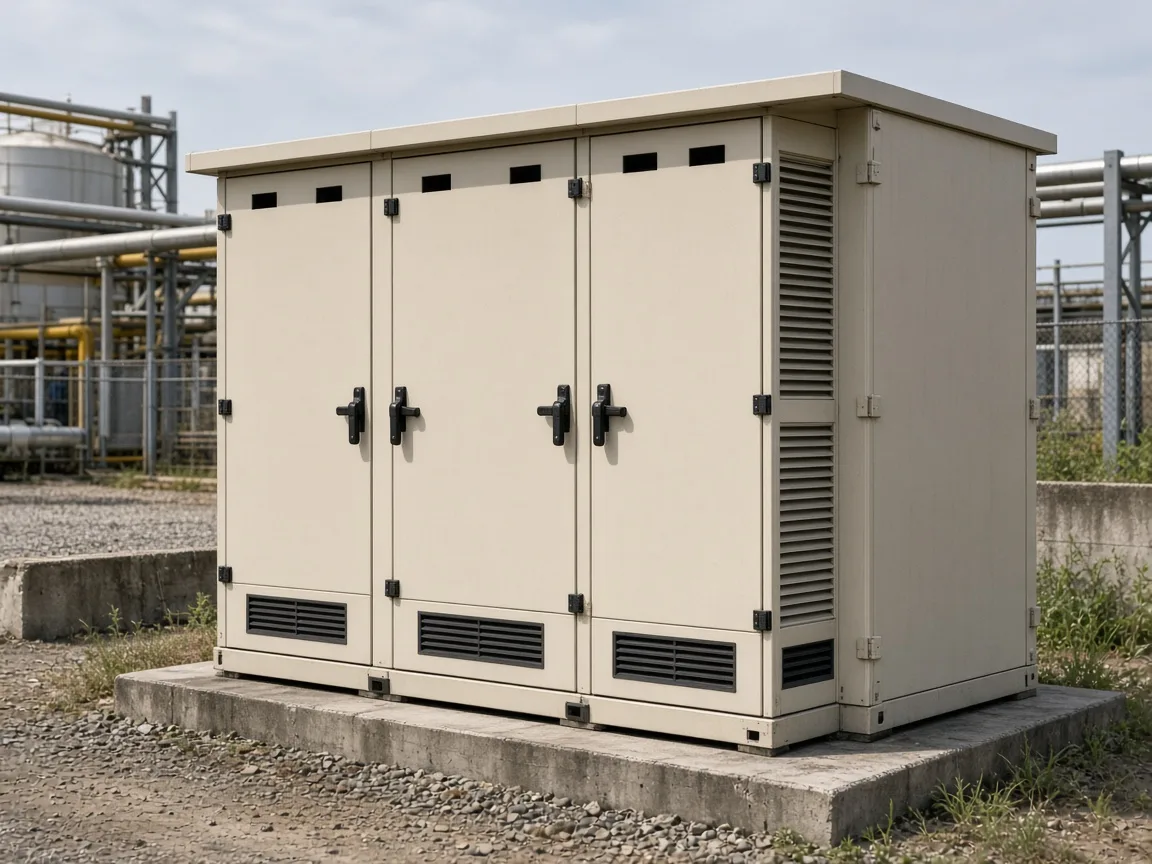
Open-rack outdoor banks suit large yard footprints and ready can access. Metal-enclosed or indoor frame packages suit process plants, limited clearances, and weather or pollution exposure that demands a cabinet.
Ingress rating is part of that decision: an IP20 indoor package is not an outdoor yard answer. Cable entry, maintenance clearances, and whether cans can be replaced without a long outage all belong on the enclosure line of the design package.
Do not pick an outdoor open rack only because it looks cheaper on a datasheet if the site is an indoor process bay.
Which HYTSC Package Fits These HV/MV Design Checks
Recommended product / solution: the HYTSC High-Voltage Dynamic Reactive Power Compensation System fits when your frozen inputs show a published six- or ten-kilovolt bus with rapidly changing industrial reactive demand.
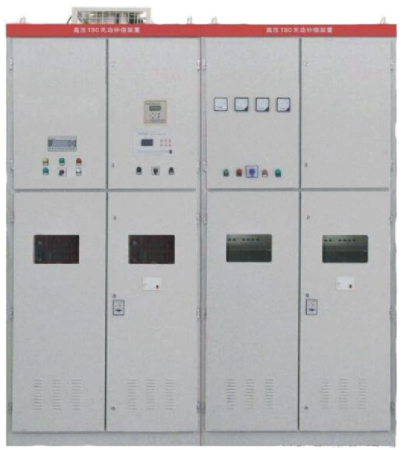
HYTSC uses thyristor-switched capacitor groups with a published response time of <=20 ms, aiming for power factor improvement to >=0.9 on compatible 6/10 kV networks. Recommended bank sizes run from 300 kvar through 3000 kvar, with reactor tuning of 6% or 13%, delta-connected capacitors, and an IP20 protection level for the published indoor-style package.
System frequency follows the value as published on the product page.
| Item | Published HYTSC value |
|---|---|
| Response time | <=20 ms |
| Switching method | Thyristor-switched capacitor banks |
| Power factor improvement | >=0.9 |
| System compatibility | 6 kV / 10 kV |
| Recommended bank sizes | 300-3000 kvar (published ladder) |
| Reactor tuning | 6% or 13% |
| Capacitor connection | Delta |
| Protection level | IP20 |
It is not the default when reactive demand is nearly constant, when the bus is outside the published 6/10 kV scope, or when you only need the general design-package sequence. For the broader HV compensation family, start from the High Voltage Power Factor Compensation Series hub after your inputs and checks are written down.
FAQ
Which design inputs must be frozen for high voltage capacitor bank design?
Freeze corrected-bus voltage and maximum operating voltage, reactive load profile, short-circuit context, harmonic cues, and site environment before locking kvar or fuse style.
Fixed, multi-stage, or thyristor-switched - how do I choose?
Choose fixed for steady reactive demand, multi-stage for slower daily swings, and thyristor-switched groups when the load needs fast MV tracking such as mills or hoists.
When does an HV/MV bank need a damping or detuning reactor?
Add reactors when more than one bank shares a substation or when harmonics would resonate with a plain bank; treat 6% or 13% style detune options as study-driven order fields.
What protection and unbalance checks belong in the design package?
State fuse architecture, unbalance detection, and the rule that remaining units must stay within allowable overvoltage after a single fuse or unit failure.
How does discharge timing affect reclosing?
Wait until residual and trapped charge have decayed-commonly on the order of five minutes in application guidance-before reclose or maintenance contact.
Outdoor rack vs indoor/enclosed - what decides?
Yard space, weather, pollution, and maintenance access decide open-rack outdoor versus metal-enclosed or indoor packages, including the published ingress rating.
How is this different from a general capacitor bank design guide?
The live general design page owns the broad inputs-to-order-package sequence; this article owns HV/MV voltage, switching duty, reactor, discharge, and unbalance checks.
When does a medium-voltage thyristor-switched package fit?
It fits when the bus matches the published HYTSC voltage class and reactive demand moves too fast for a fixed bank, matching published response, size, and reactor options.
References
- PJM V.G Design and Application of Shunt Capacitors
- Svenska kraftnat TR01-17e Shunt Capacitors Banks
- CIGRE Electra TB 817: Shunt capacitor switching in distribution and transmission systems
- EEP: Providing capacitive reactive compensation with shunt capacitor banks
- Physics Forums: Design of Power Factor Correction Capacitor?
- Physics Forums: Substation Capacitor Bank Problem