
 Zhejiang Hongyan Electric Co., Ltd.





































Capacitor banks for reactive power compensation supply leading kvar so an inductive plant draws less reactive current from the transformer and feeder. The rest of this page covers how to read a kvar target, when steps must switch, what light load does to a fixed bank, and when detuning comes before the order. A harmonic-filter decision is a separate job and is not specified here.
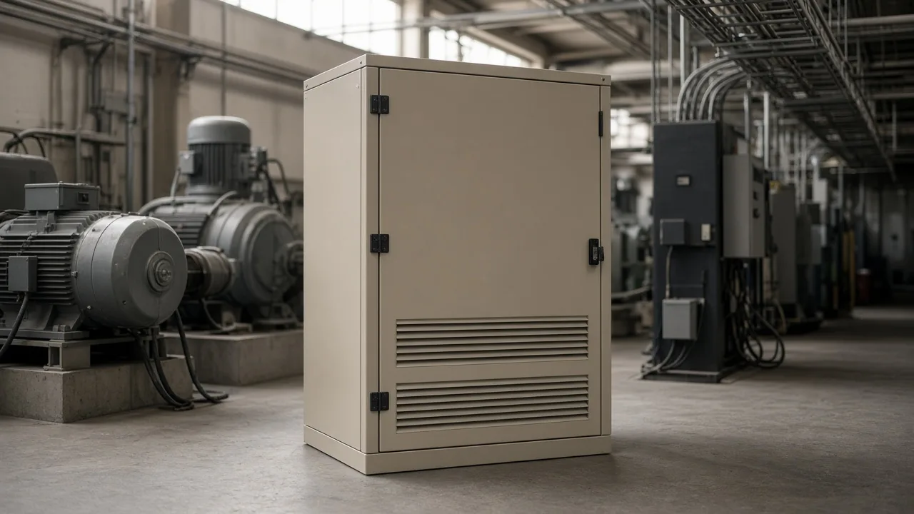
What Capacitor Banks Supply on an Inductive Bus
A shunt capacitor bank injects leading reactive power so motors and transformers do not pull all of that kvar through the upstream feeder.
Motors and transformers need magnetizing current. That current is reactive power: cables and transformers must carry it, and it is not shaft power or useful heat at the load. Buyers already see the symptom as power factor, lagging when the inductive plant dominates.
Most plant loads lag, so the usual fix puts a shunt bank in parallel with the bus and lets it supply the leading vars locally. Series compensation and rotating condensers show up in transmission practice. They are not the package this buyer is ordering.
The practical results people specify are a higher power factor, less current for the same real power, and a bus voltage that sags less when motors start. Loss reduction follows from lower current. It is not a guaranteed savings percent, and this page does not invent one.
Placement still matters. A commenter on a worked shunt-compensation note asked why the capacitors sat at the load instead of on the bus where the meter was watched. Both spots can be right: at the load, the feeder upstream of that point is relieved; at the main bus, one bank covers many feeders and the transformer still sees the benefit only for current that no longer leaves the site.
Wider high-voltage compensation hardware still routes through the parent HV power-factor series once voltage class is clear. A live power-factor correction article already owns the bill-penalty narrative; this page owns the switching and resonance gate.
How to Read a Kvar Target Without Treating One Example as Universal
Estimate kvar from measured kilowatts and the power-factor angles you actually have; treat any single published example as that network only.
The common engineering form is reactive power compensation equal to real power times the difference of the tangents of the two power-factor angles. You need the operating kilowatts, the present lagging power factor, and the target the utility or the plant standard actually uses. A nameplate motor list is not a substitute for a loaded measurement.
One published tutorial network, an 11/0.4 kV transformer feeding an inductive load, calculated 217.8 kvar to move the high-voltage side from about 0.839 lagging to 0.95. That figure belongs to that model. Copying it onto a different plant will over-correct or under-correct.
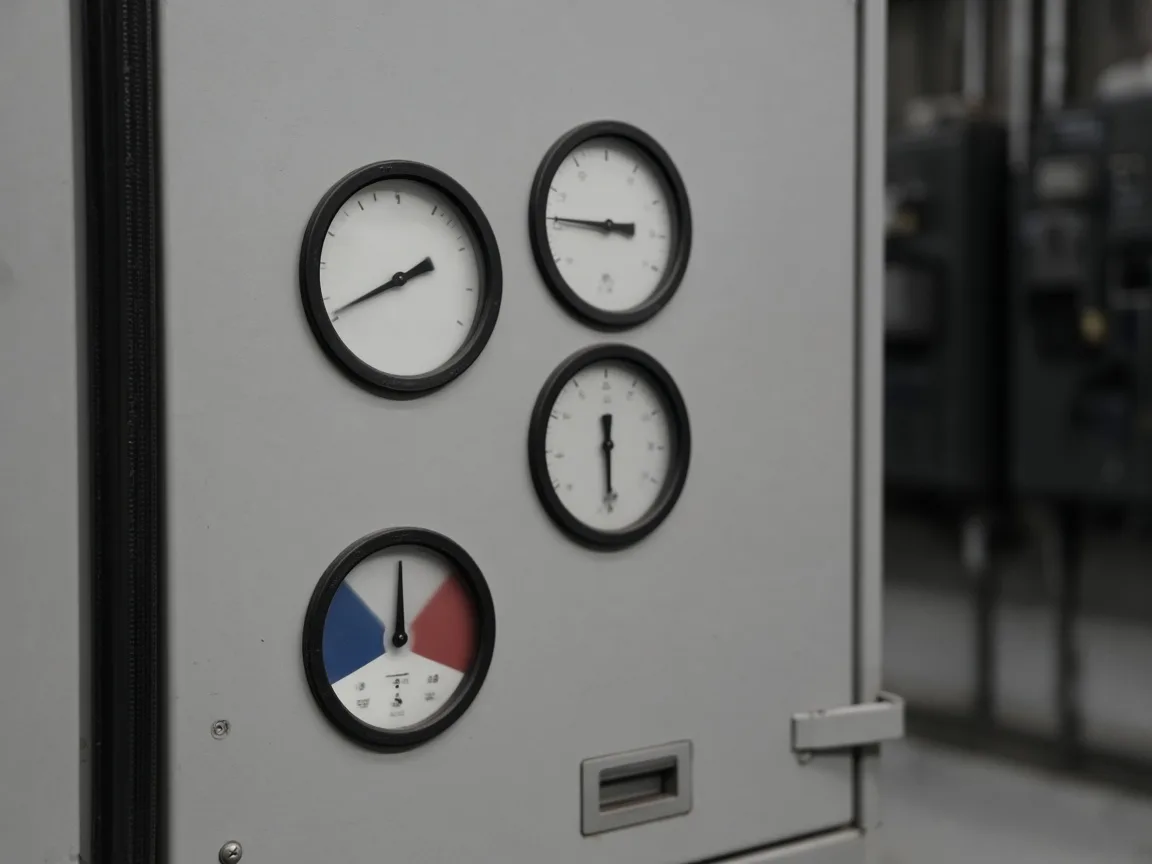
Read the example as a method check, not a catalogue rating. If your load is larger, the kvar grows with the real power and with how far the present angle sits from the target. If the plant already sits near the target at peak, the bank may be small — or unnecessary — until a new motor line arrives.
Ask for the measurement window. A single midday snapshot misses the night valley that decides whether the bank must be switched. The sizing conversation and the switching conversation are the same conversation.
Fixed Banks Versus Switched Steps
Use a fixed capacitor bank only when kvar demand stays steady; use a switched capacitor bank when the plant unloads.
A fixed bank is energised with the feeder and left in service. It is the cheaper choice for a continuous inductive load such as a process line that does not shut groups of motors down. There is no controller to maintain, and there is also no way to remove kvar when the load leaves.
A switched capacitor bank splits the same total kvar into steps. Equal steps are simple to operate.
Unequal steps can follow a load that jumps in large blocks, such as one large mill plus several smaller auxiliaries. Automatic control usually watches power factor, voltage, or both, and closes only the steps the present load can absorb.
| Arrangement | Fits when | Fails when |
|---|---|---|
| Fixed capacitor bank | Inductive kvar barely changes between shifts | Night load drops and the bank stays fully in |
| Switched capacitor bank | Motors start and stop through the day | The controller has no current or voltage signal, so steps never track |
| Multi-step automatic bank | Several load blocks share one bus | Step sizes are larger than the smallest load change you care about |
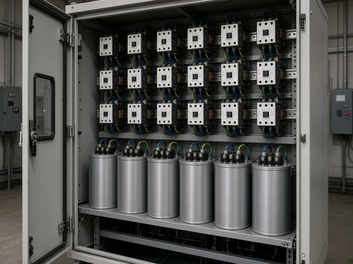
Over-correction is the failure mode that makes switching worth the hardware. A bank sized for the afternoon peak becomes too much capacitance when half the motors are idle. The next section is that case, not a second definition of power factor.
What a Bank Left Online Does at Light Load
If the night load falls and a fixed bank stays in, the plant can go to a leading power factor and switching inrush rises.
Practitioners describe the same night-shift picture: motors that pulled the power factor down are idle, the capacitors are still fully online, and the meter swings leading. A leading power factor means the site is exporting vars. Some utilities bill the lagging side more explicitly, but the local system still sees voltage rise, flicker complaints, and harder switching.
Tip: Excess capacitance left online after the motors stop is a leading-power-factor problem with large inrush on the next close — practitioner night-shift case.
The remedy on a switched bank is ordinary: open steps until the remaining kvar matches the remaining load. A reply on the same thread notes that capacitors are simply switched off when too much reactive power is being produced. That is an operating rule, not an exotic controller feature.
Do not “solve” light load by adding more capacitors. The bank is already ahead of the load. The specification question is how small the last step is, and whether anyone is allowed to leave every step closed on a time clock that ignores the meter.
When a Plain Bank Needs Detuning
On a drive-rich bus, check harmonic resonance before a plain shunt capacitor bank is energised.
Nonlinear loads inject current at a handful of harmonic orders. A plain capacitor’s reactance falls as frequency rises, so the bank becomes a sink for those currents.
Together with transformer and feeder inductance, the bank can sit near a parallel resonant point. Application notes aimed at industrial plants put that risky band around the 5th through the 13th harmonic — the same orders many drives produce.
The symptoms are not subtle: blown capacitor fuses, tripped breakers, and capacitors that run hot and fail early. Resonance is self-correcting only in the worst way, because a failed capacitor changes the tune by destroying itself.
Important: A plain bank on a drive bus can magnify harmonics near the 5th through the 13th — industrial application-guide condition, not a universal limit.
A detuned reactor in series with the capacitors moves the branch resonance below the lowest significant harmonic. At power frequency the branch still supplies kvar.
At the dominant harmonic it is no longer a welcoming low-impedance path. That is a detuned capacitor bank, not a promise that every harmonic disappears.
Tuned filters, which intentionally attract one harmonic, are a different specification and a different cost. If the measurement shows distortion past the utility limit, hand the job to a filter study. Do not stretch a detuned power-factor branch into a filter it was not ordered to be.
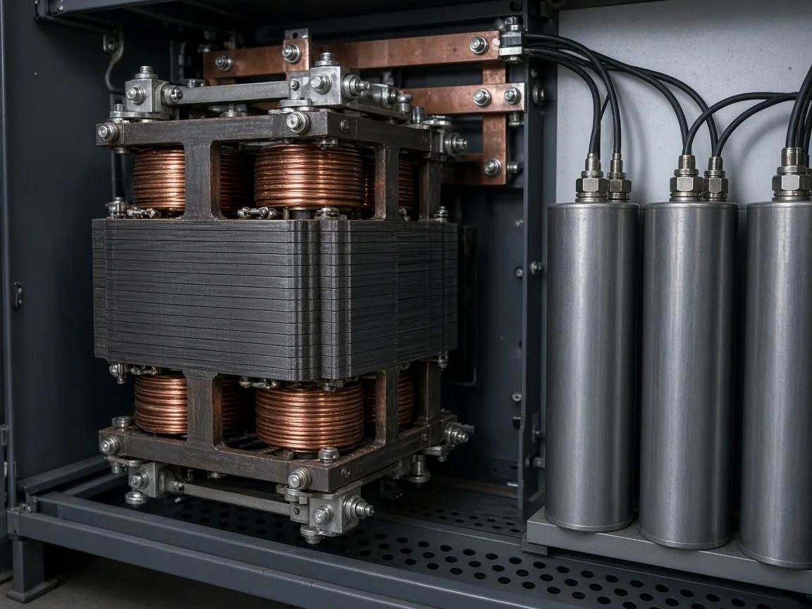
Ask for an impedance scan or at least a harmonic snapshot before the order when variable-speed drives, rectifiers, or furnaces share the bus. A quiet motor-only plant can still use a plain bank. A mixed plant should not guess.
When to Select an End-Point Compensation Box
Select the end-point compensation box when kvar should sit beside the motors on a low-voltage feeder and the published steps cover that feeder.
End-point compensation box — the HYTBBM end-point device — is installed close to motors, feeders, or other inductive loads that need local compensation. The page allows balanced, phase-separated, and hybrid modes, plus an optional fixed-capacitor step. It is not a mill harmonic filter, and it is not the medium-voltage outdoor cabinet already shown on the live design article.
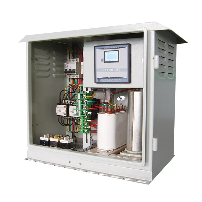
| Published item | Page value |
|---|---|
| Rated voltage | 380 V, three-phase |
| Rated capacity | 30 / 45 / 60 / 90 kvar, or a custom step |
| Modes | Balanced, individual phase, or hybrid |
| Fixed step | Optional |
| Control | Reactive power |
| Mechanical switch response | at or under a quarter-second |
| Electronic switch response | at or under 20 ms |
| Power factor target on the page | at or above 0.9 |
| Steady voltage window | down 15 percent to up 10 percent, holding through 418 V |
The HYTBBM end-point device is the shortlist item when the feeder is low voltage and those kvar blocks cover the load. A tuned filter for mill drives is a different order.
Bring feeder voltage, the compensation mode, and whether a fixed step is also required. Those inputs do not replace the light-load and resonance checks above.
FAQ
What do capacitor banks for reactive power compensation actually supply?
They supply leading reactive power in parallel with an inductive bus, so the upstream transformer and feeder carry less lagging kvar while real power still comes from the grid.
Why compensate reactive power instead of only buying a larger transformer?
The transformer and cables must be sized for the current, including reactive current. Local kvar can free capacity and ease voltage sag, but it does not replace a transformer that is already short of real-power rating.
How is kvar estimated for a target power factor?
From operating kilowatts and the tangent difference between the present power-factor angle and the target angle. A published 217.8 kvar example belongs only to that tutorial network.
When is a fixed bank the wrong choice?
When inductive load changes through the day or drops on a light shift. A fixed bank cannot open, so it keeps exporting vars after the motors stop.
What goes wrong if the bank stays online at light load?
The site can swing to a leading power factor, bus voltage can rise, and the next close sees a larger inrush. Switch steps off until kvar matches the load that remains.
When should the bank be detuned or replaced by a filter?
Detune when drives or other nonlinear loads share the bus and a plain bank could resonate. Move to a filter specification when the goal is to pull a named harmonic down to a limit, not only to keep power factor.
Where should compensation sit — at the load or at the main bus?
At the load when you want that feeder relieved. At the main bus when one bank must cover many feeders. The meter location does not by itself pick the electrical location.
What does the outdoor MV package need from the buyer before order?
This shortlist is the low-voltage end-point box, not an outdoor medium-voltage cabinet. Ask for feeder voltage, the compensation mode, and whether a fixed step is required.
References
- Power factor correction capacitor bank — Physics Forums
- Reactive Power Compensation using Capacitor Bank — Power Projects