
 Zhejiang Hongyan Electric Co., Ltd.





































A shunt capacitor bank raises bus voltage by feeding capacitive vars into the bus, so less lagging current has to come from upstream. how capacitor bank improve voltage is that settled rise, and it stops helping once the bus is already high. The walk from here covers the rise itself, the weak-bus case, and the light-load point where the same bank should come off.
Operators notice the change on the bus voltmeter a moment after the breaker closes and the current settles. Power factor moves as a side effect. The settled bus voltmeter is the reading under discussion.
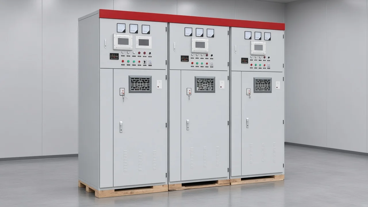
What the bus does when shunt vars arrive
The bus rises because capacitive vars replace lagging current that had been imported through upstream impedance.
Inductive motors and transformers still need magnetizing current. Before the bank is in, that current travels from the source through feeder and transformer reactance, and the bus sits lower than the upstream voltage.
A shunt capacitor bank supplies that reactive power at the bus. Upstream current falls, the reactive part of the voltage drop shrinks, and bus voltage climbs.
Picture a mill bus while the crushers are running. The voltmeter has sagged, the operator closes one capacitor step, and the bus recovers without anyone changing the transformer tap.
The real power of the crushers is still coming from upstream. What changed is where the vars come from.
Capacitor banks for reactive power compensation do this only on the bus side of the bank. Feeders and loads past the connection still see their own current. A bank at the main bus does not correct a motor out at the end of a long lateral, and a bank at that motor does not lift every other bus on the site.
| Operating case | Reactive flow through the upstream path | What the local bus does |
|---|---|---|
| Bank open, load still inductive | Lagging vars imported from the source | Bus sits below the upstream voltage |
| Bank in, vars still short of the load | Less lagging import | Bus voltage rises |
| Bank vars larger than the inductive load | Vars export toward the source | Bank bus can sit above the upstream bus |
The middle row is the useful case. The bottom row is the same physics with the sign flipped, which is why a rise is not automatically a success.
Why a weak bus moves farther than a stiff bus
The same vars move a weak bus farther because the rise tracks bank reactive power over the short-circuit level.
Short-circuit level is the practical name for how stiff the upstream system is. A bus with high short-circuit power has a small source impedance, so a given block of vars produces a small voltage change.
A long feeder or a lightly tied industrial bus has less short-circuit power, and the same block moves the needle more. That is why two plants can install similar banks and see different voltmeter changes.
Divide the bank’s reactive power by the three-phase short-circuit power at that bus. That ratio is a first look at the fundamental-frequency change, not a substitute for a load flow when several banks, taps, and generators all move. A planner asks for fault level before arguing about step size, as set out in Review of capacitor control.
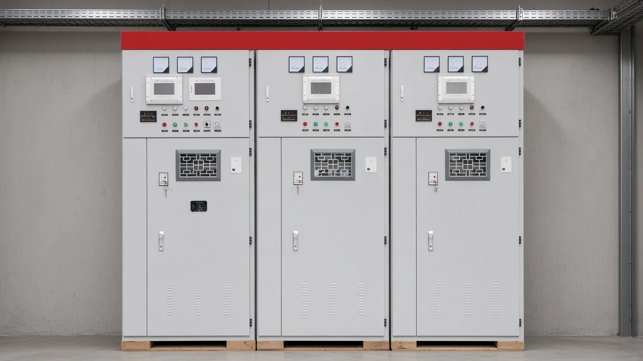
Heavy load changes the picture only slightly. Improving the power factor also trims current, which trims loss, which adds a little more rise. The first-order move is still the vars through the reactance.
A strong bus can absorb a large bank and barely show it. A weak bus can look high after one extra step.
Where those vars push the bus too high
The bus is too high when the step is already large, or when the bank exports vars and the local voltage passes the upstream bus.
Planners often hold that fundamental-frequency step to 2–3% so the close of the bank is not a hard bump for downstream loads. That ceiling is the planning habit in these shunt-capacitor slides.
It is a limit on the step, not a promised improvement, and it says nothing about kilowatt-hours or payback. A smaller step simply switches fewer vars, so the bus moves less each time the breaker closes.
The second limit shows up at light load. While the plant is inductive, the bank cancels part of the imported vars and the rise is welcome. After the motors stop, those vars have nowhere local to go.
They flow back toward the source. Leading current through the upstream reactance reverses the reactive drop, and the bank bus can sit above the supplying bus. A fixed bank sized for the afternoon peak is the usual way to get there on a Sunday night.
From the field: A forum reply on motor-capacitor sizing warned that pushing correction all the way to unity can generate high voltages — EEVblog thread.
That warning is a workshop-scale comment, not a substation measurement. It still matches the plant pattern: more capacitance is not automatically a higher-quality bus.
At more than one compensation level, upstream inductance can resonate with the bank. The voltage problem operators see on a quiet shift is usually the exported vars, visible on the two bus voltages and on the sign of the reactive flow.
How a settled rise differs from a switching spike
A settled rise is the new fundamental-frequency voltage after the bank is on; a spike is the brief overshoot at the close.
When the breaker shuts, the bank voltage has to come up from zero and the current surges. That disturbance can ring and stress insulation for a fraction of a second. The voltmeter reading that remains a minute later is a different fact.
It is the bus sitting at a new value because the vars are still connected. Protection and pre-insertion hardware belong to the spike. Step size, short-circuit level, and whether the load is still inductive belong to the reading that stays.
Mixing the two leads to the wrong fix. A reactor in series with the bank can tame inrush and detune a harmonic. It does not decide whether the settled bus is high at midnight.
Taking a step offline does. If the event log shows a peak only in the first cycles and the bus then returns to the pre-close value, the story is the transient. If the bus is still high after the alarm clears, the story is vars that the load is no longer absorbing.
Which shunt cabinet is the product fit
The fit is a shunt cabinet that can supply the vars and drop a group when the inductive load leaves.
On the high-voltage compensation series, the HYTBB medium and high voltage reactive power compensation cabinet is built as that shunt bank for inductive reactive power. The HYTBB cabinet is rated 10(6)–35 kV, 50 Hz, and 50–20,000 kvar, with the neutral connection shown as isolated neutral or non-effective grounding. Group control on this cabinet can be fixed, or it can be manual or automatic, which is the difference between a block that stays in and steps that can follow the load.
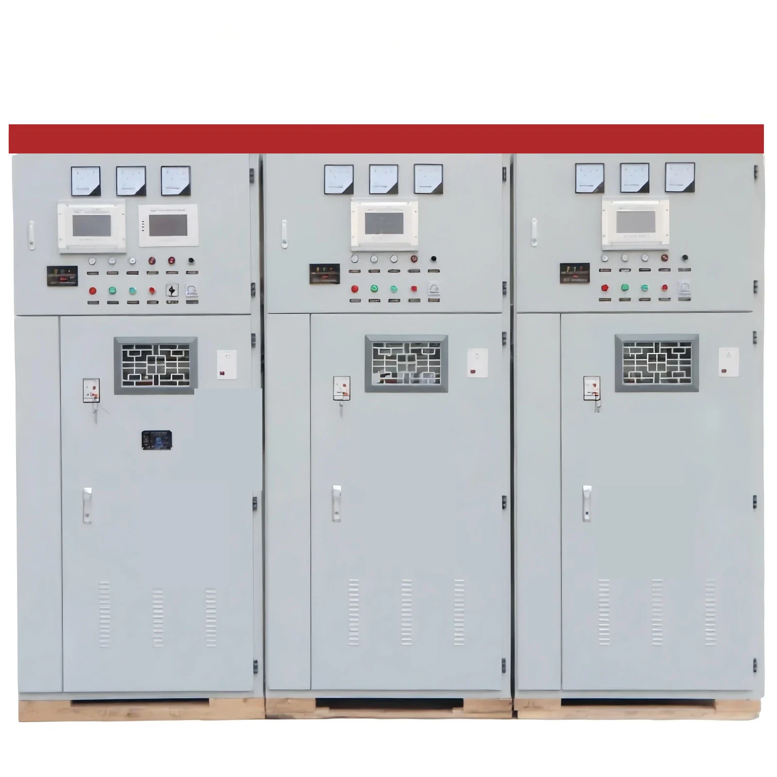
A fixed group is a reasonable fit when the inductive floor of the plant never falls below the vars that group supplies. A weekend shutdown, a batch process, or a feeder that unloads at night fails that test. Automatic or manual groups let the operator remove vars as the bus climbs: in at heavy load, out at light load.
This cabinet is a poor fit when the bus swings in seconds, as with an arc furnace that needs a dynamic compensator, or when the only question on the table is the inrush transient. Neighboring equipment on the high-voltage power factor compensation series covers other reactive-power jobs. The voltage decision here is still whether a shunt step can come out before the bus is too high.
What to compare before the next step closes
Compare bank output, both bus voltages, remaining load vars, and any tap movement before adding another step.
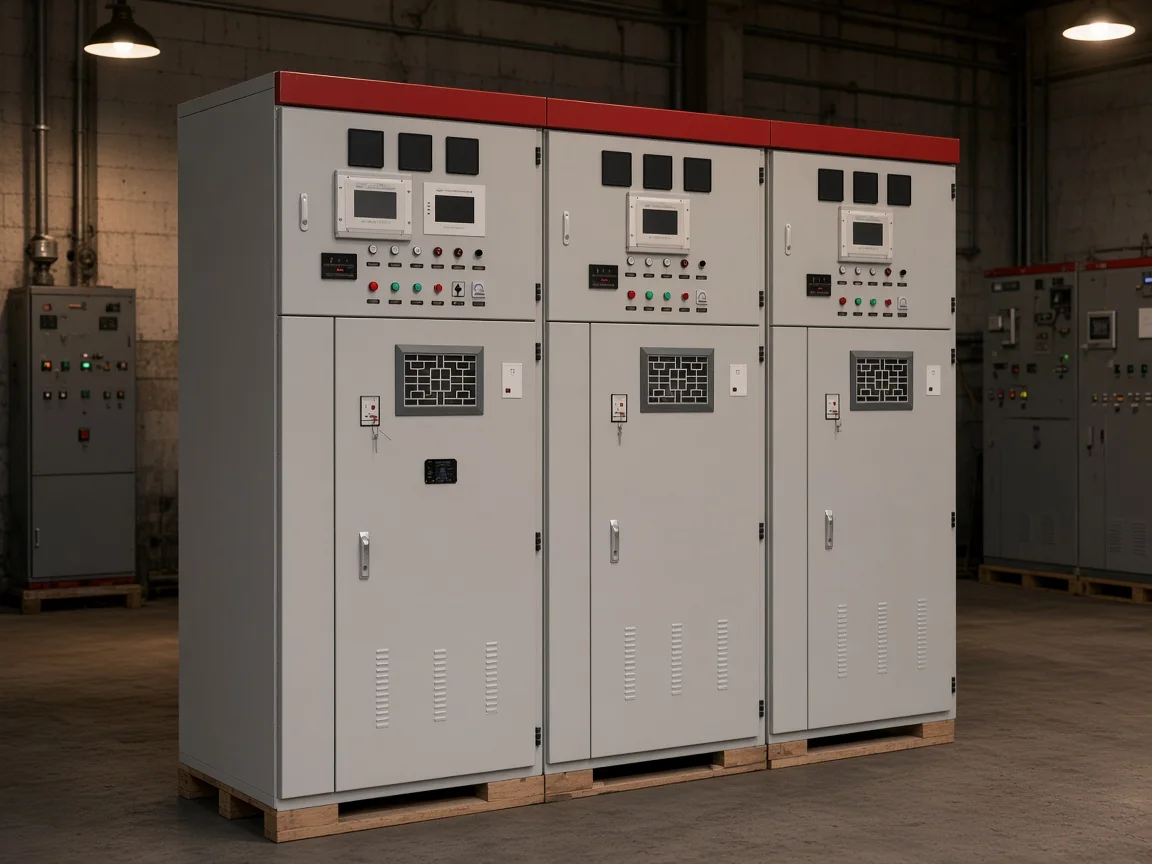
A load tap changer can hide or exaggerate the bank. The bank closes, the bus jumps, and the changer drops a tap a minute later. The net reading looks almost unchanged, and someone adds another capacitor step.
Later the changer is already at its lowest buck tap, the extra step is still in, and the quiet shift goes high. Controller practice puts extra delay on the tap changer after a bank operation so the two devices are not correcting each other.
| Reading | What it decides |
|---|---|
| Bank current or vars | The step is actually connected, not merely commanded |
| Local bus voltage and upstream bus voltage | Whether the bank bus has climbed past the source |
| Load vars versus bank vars | Whether the bus is still absorbing lagging vars |
| Tap or regulator position | Whether another device already spent its downward range |
Take the four readings at the same time. A voltage that is high only on one screen, with the bank current at zero, is a metering or scaling problem.
A voltage that is high on both the local and upstream meters, with the bank clearly in and the load vars below the bank vars, is the export case. Another step would add to it.
FAQ
Can a capacitor boost voltage?
On an AC bus, a shunt bank can raise the fundamental-frequency voltage by supplying vars locally. That is not a DC boost converter and not a promise of a fixed percent gain. The bus moves only as far as the vars and the upstream impedance allow.
Does a capacitor reduce voltage?
A shunt bank does not pull a healthy bus down. It raises the bus while it cancels imported lagging vars, and it can push the bus still higher if it exports vars. A shunt reactor is the device that absorbs vars and normally lowers the bus.
How does a capacitor bank improve power factor?
It supplies leading vars so the source current is less lagging, and the power factor moves closer to unity as a result. The voltage change is the other half of that same current reduction. Power factor can look acceptable while the quiet-shift voltage is already high.
What is the main purpose of a capacitor bank?
In this setting the bank’s job is local reactive power for an inductive system, which unloads upstream equipment and lifts a bus that had been sagging. Holding a backup supply, filtering every harmonic, or surviving a switching study are different jobs.
Should fixed banks stay on when the inductive load is gone?
No, if the remaining load no longer absorbs those vars. The bank then exports reactive power and the bus can rise. Switched groups, or a fixed group no larger than the lowest inductive floor, keep that export from becoming the normal night condition.
Can the bank bus sit higher than the upstream bus?
Yes. Once local capacitive support exceeds local inductive demand, reactive flow reverses and the bank bus can exceed the supplying bus. Compare the two voltages at the same moment before treating a high reading as a metering error.