
 Zhejiang Hongyan Electric Co., Ltd.





































A capacitor bank for 3 phase motor belongs on that motor circuit only when the capacitor must switch off with the motor. Shared reactive power stays on the plant bus, while a medium-voltage shunt cabinet serves the shared case rather than the motor leads.
An induction motor on a balanced three-phase supply already builds its rotating field from the three line currents. The capacitor does not create that field. It supplies lagging magnetizing current closer to the motor, which is power factor correction, not a start or run winding.
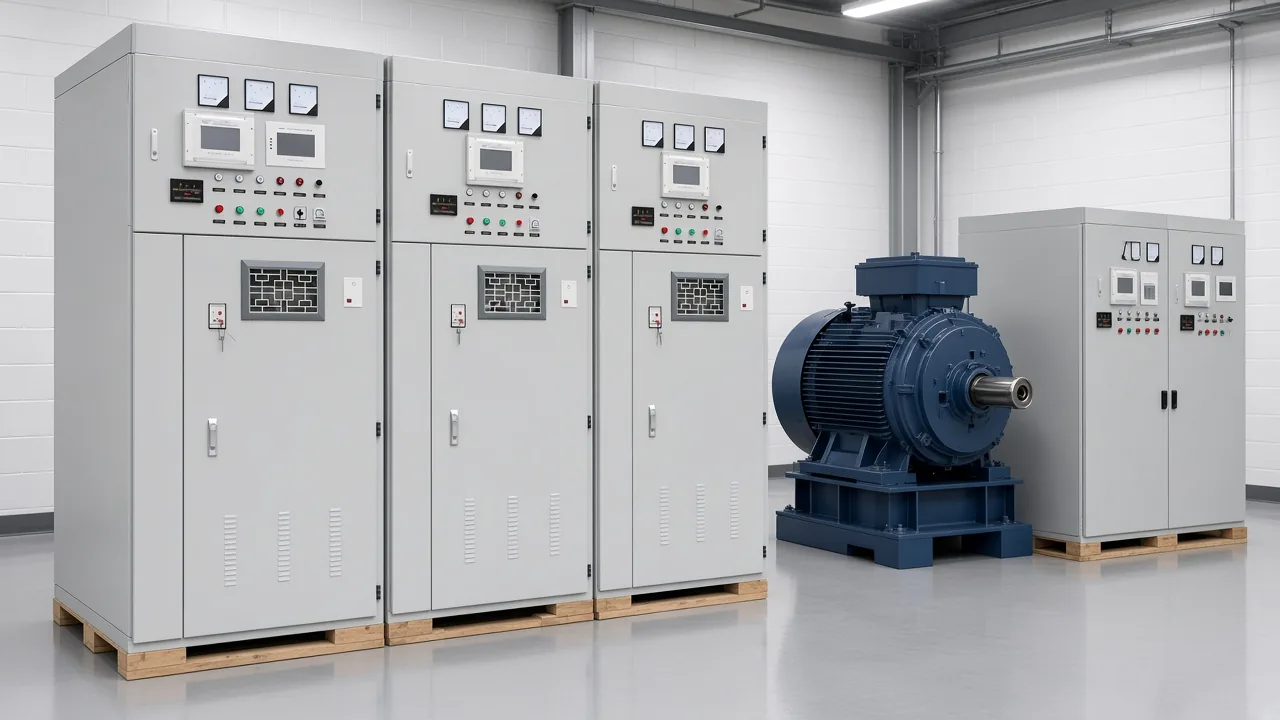
Put the capacitor on the motor circuit when it must leave with that motor
Put the capacitor on the motor circuit when that motor is the only load you want corrected, and the capacitor must open with the motor controller.
A single crusher, compressor, or pump that starts and stops on its own is the usual case. While it runs, the local capacitor feeds magnetizing current at the motor leads, so the feeder upstream carries less reactive current. When the motor controller opens, the capacitor leaves with it.
That landing uses the controller as the capacitor disconnect. A separate disconnect is not required for a capacitor connected on the load side of the motor controller. The starter already opens the ungrounded conductors together, which is the point of putting the capacitor downstream of it.
The same landing fails when the motor is one of many on a feeder and the capacitor is sized for the group. One idle motor would still see a bank meant for the whole group, or the bank would stay online after that motor stopped. Either result is a placement error, even before anyone talks about microfarads.
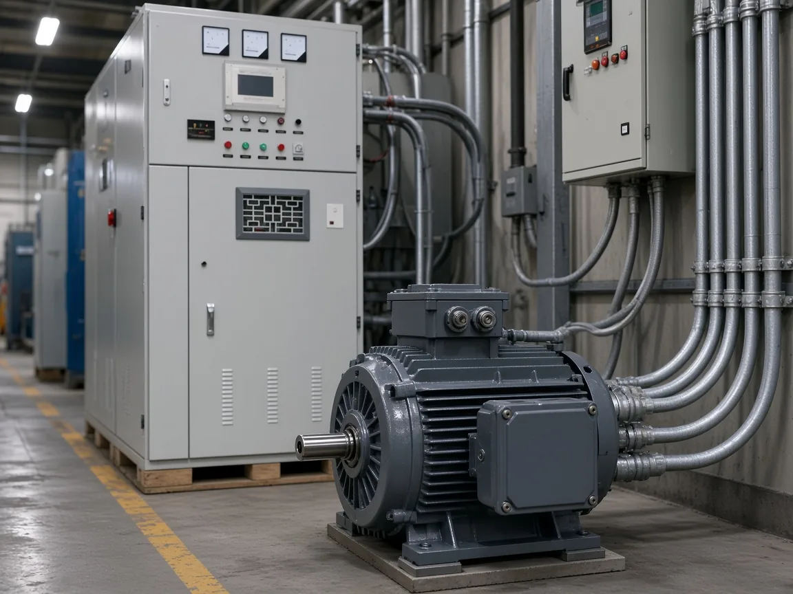
Leave shared reactive power on the plant bus
Leave the reactive power on the plant bus or a motor control center when many motors share one metering point and no single motor should carry the bank.
A plant bus bank, or a bank at the motor control center, corrects the combined lagging load. Many utilities charge a penalty if power factor dips below 95 percent. DOE motor guidance treats that shared correction as a choice between capacitors at each motor and capacitors at the motor control centers.
The bus choice has a limit that buyers miss. Unity on the utility side of the bank does not remove reactive current in the feeders between the bank and the motors.
Those feeders still carry magnetizing current, still heat, and still use transformer capacity downstream of the bank. Power factor correction at the meter is a billing result.
It is not the same as unloading every motor branch.
From the field: On the industrial automation forum, Rabert wrote that capacitor banks are either linked across the supply itself or switched together with the motor — three-phase motor capacitor thread.
A second forum note splits the same choice into three landings: the main distribution board, a local board for one area, and the terminals of an inductive load such as a motor. Use the main board when the penalty is the problem.
Use the local board when one area’s feeders are the problem. Use the motor terminals only for the motor that actually runs.
A fixed bank left on an empty plant drifts leading. The motors that created the lag are gone, and the capacitors remain.
Automatic steps at the bus can drop off with the load. A capacitor tied to one motor controller drops off only for that motor, which is why the two schemes are not substitutes.
| Landing | What it corrects | When it comes offline | What it does not do |
|---|---|---|---|
| Motor circuit | Magnetizing current of that motor | With the motor controller | Correct the rest of the plant |
| Motor control center | A group of motors on that lineup | With the group steps or the lineup | Unload a long feeder beyond the lineup |
| Plant bus | Combined lag seen at the meter or bus | With bus steps, if they are switched | Remove reactive current downstream of the bank |
Self-excitation is the limit on a motor-terminal capacitor
Keep a motor-terminal capacitor from exceeding the motor no-load current, because a larger capacitor can self-excite the machine after the contactor opens.
Self-excitation here means the spinning motor and the capacitor keep a voltage alive after the supply is gone. The machine is no longer just a motor.
It is generating into the capacitor. EC&M describes that overvoltage as high as two times source voltage, with inrush as much as 20 times normal full-load current if the motor is reclosed before the capacitor has discharged.
Transient torque follows that out-of-phase reclose.
When motor data does not state a maximum capacitor, keep capacitor current from exceeding no-load current, normally about 15 percent of motor kVA and short of about 95 percent power factor. That is a ceiling, not a target to round upward.
A clamp meter on the motor with the shaft unloaded is the check. A horsepower chart is not.
Light load makes the same capacitor look larger. The magnetizing current is still there, while real power has fallen.
A fixed capacitor chosen at full load can push the motor circuit leading when the motor idles. That is another reason a motor that often runs unloaded is a poor place for a fixed capacitor, and a better candidate for a stepped bank farther upstream.
Do not treat a stand-alone generator conversion as this decision. Sizing capacitors so an induction machine builds its own voltage off the grid is a different job, with a different failure if the capacitance is short. Grid-connected power factor correction wants the opposite: the capacitor must die when the contactor opens.
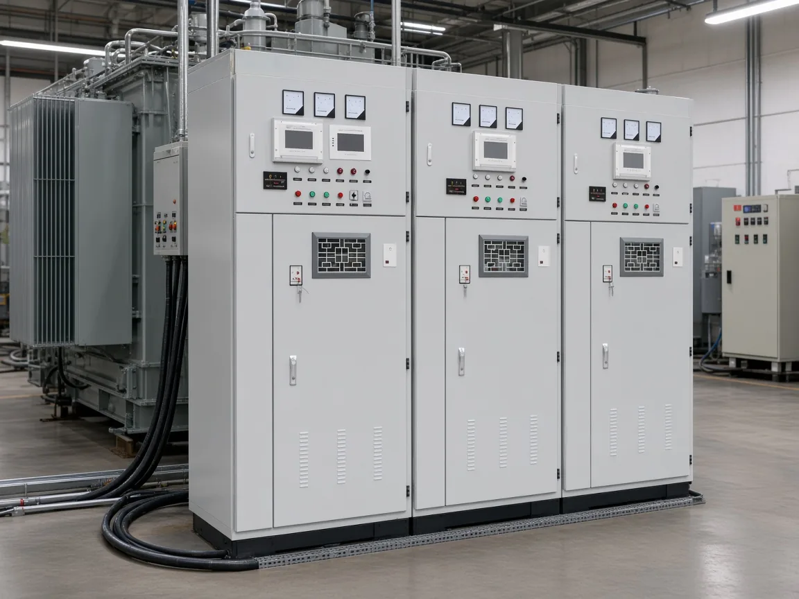
Overload and conductor rules follow the connection point
Land the capacitor on the load side of the overload only if you reset that overload from measured current, and still size the capacitor conductors for the capacitor.
With the capacitor downstream of the motor overload device, reactive current circulates between the motor and the capacitor. It no longer flows through the overload.
The overload setting has to follow the improved power factor of that motor circuit, or the heater is too large for the current it now sees. The motor-circuit conductors back to the starter are a separate matter.
The capacitor is ignored when those conductors are sized under the motor branch-circuit rule.
Capacitor-circuit conductors need an ampacity not less than 135 percent of the capacitor rated current, and a run out to the motor terminals also needs at least one-third of the motor-circuit conductor ampacity.
The overload ampere change after a downstream capacitor varies from 10 percent to 35 percent with motor speed and horsepower, so the new setting comes from current measured through the motor overload device. Measure before and after the capacitor is connected, on the loaded motor. A generic percent copied from another frame will not match this one.
For a capacitor rated 1,000 volts or less, residual voltage is brought to 50 volts within 1 minute after disconnection, and that discharge path cannot depend on someone closing a switch by hand. The discharge path is part of the capacitor or it connects automatically.
That one-minute rule is the low-voltage motor-capacitor case. Higher-voltage capacitor equipment follows a different part of those rules, including isolation that shows a visible gap.
Do not paste the one-minute rule onto a medium-voltage bus cabinet.
A separate overcurrent device is not required when the capacitor sits on the load side of the motor overload device. The motor protection is already there. The capacitor conductors still have to be large enough for the capacitor, which is why the tap rule and the 135 percent floor travel together.
| Connection detail | What changes | What stays |
|---|---|---|
| Capacitor on the load side of the motor controller | Separate capacitor disconnect is not required | Capacitor still needs a discharge path |
| Capacitor on the load side of the motor overload device | Overload setting follows the improved current | Motor-circuit conductor ampacity ignores the capacitor |
| Capacitor conductors to the motor | Ampacity floor is the capacitor current and one-third of the motor circuit | Those conductors are not sized as if they were the motor branch alone |
| Capacitor at 1,000 volts or less | Residual voltage to 50 volts within 1 minute | A hand-operated discharge switch is not the method |
A medium-voltage cabinet is a shunt bank, not the motor capacitor
The HYTBB cabinet is a shunt bank for a medium- or high-voltage system, not a capacitor that starts or runs a three-phase motor. Treat that cabinet as a shunt capacitor bank on the bus.
Read the cabinet as bus equipment. It compensates inductive reactive power on a power-frequency system, and it can be fixed or switched in groups.
That is the plant-bus side of the placement choice. It does not belong across the leads of a low-voltage motor starter, and it does not replace the small capacitor that would switch with that starter.
Ordinary industrial motors are described as 60 Hz sinusoidal machines, which stays separate from the cabinet frequency in the rating table. The motor-circuit rules above stay with the low-voltage capacitor that actually lands on the starter.
Series reactors, group switching, and a neutral arranged for an ungrounded or non-effectively grounded system are bus-cabinet topics. They answer how a shared bank lives on a medium-voltage system. They do not answer how large a capacitor may be on one motor before self-excitation.
Select a bus-bank product only for the shared reactive load
Select this bus-bank product when the reactive power is a shared system load at the published cabinet ratings, not when one motor circuit needs a switched capacitor.
The HYTBB cabinet rating table lists 10(6)–35 kV, 50 Hz, and 50–20,000 kvar, with a neutral connection of isolated neutral or non-effective grounding.
That sentence is the fit test. Voltage in the medium- and high-voltage band, a shunt role, and a neutral arrangement for the system grounding all point at a bus or distribution bank.
A three-phase motor circuit at utilization voltage fails that test even when the motor is large. The motor can still have its own low-voltage capacitor, switched by its motor controller, while the cabinet serves the bus those motors sit behind.
The high-voltage power factor compensation series is the family for that bus job. Inside it, the HYTBB medium- and high-voltage reactive power compensation cabinet is the shunt cabinet whose table was used here.
Choose it when several loads share the reactive demand and the system voltage matches the table. Leave it off the short list when the only question is a capacitor on one motor starter.
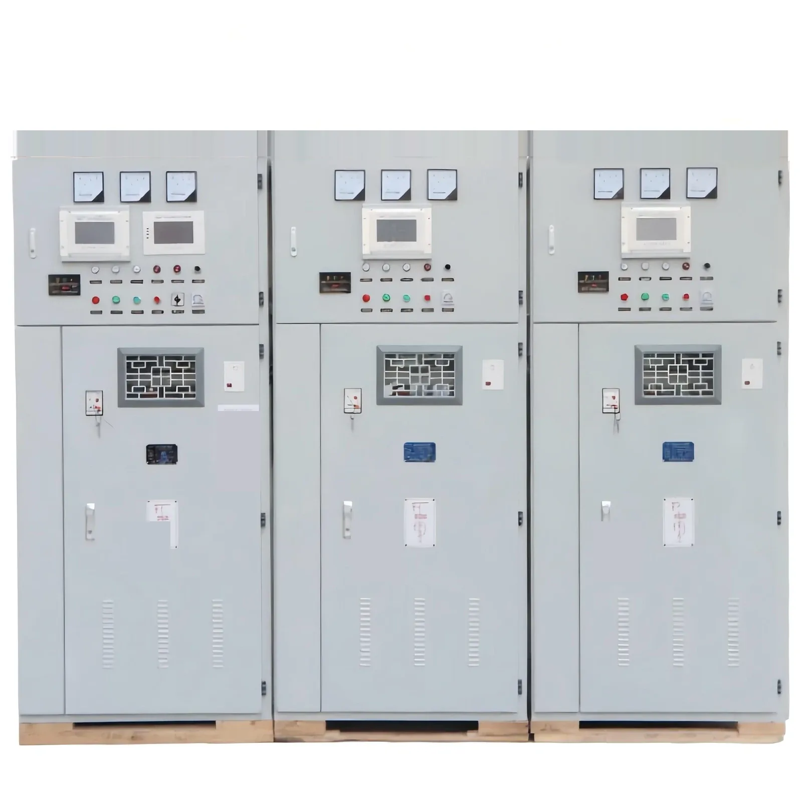
Switching on the cabinet can be fixed or grouped and automatic. Grouped switching is what keeps a bus bank from sitting fully on after the plant load falls.
It is still bus control. It is not the same contactor that starts the motor.
FAQ
Do you need a capacitor for a 3 phase motor?
Not for torque. The three windings already produce the rotating field. Add a capacitor only when you have decided to correct that motor’s lagging current, and only at a size that stays within the no-load current.
How do I connect a 3-phase motor to a capacitor?
Decide the landing first. On the load side of the motor controller, the capacitor switches with the motor.
On the plant bus, it does not. This is not a delta-wiring recipe for running the motor from a single-phase supply.
What size run capacitor for 3/4 hp motor?
That question belongs to a single-phase run capacitor, which shifts a start or auxiliary winding. It is not the kvar decision for a three-phase motor on a three-phase supply.
When to use capacitor bank?
Use a bank on one motor circuit when that motor is a steady inductive load and the capacitor must leave with it. Use a motor control center or plant bus bank when the lag is shared and the utility penalty, or the bus loading, is the problem you are solving.
Should the plant bank stay on after the motors stop?
No, if it is a fixed bank. With the motors off, the capacitors are the remaining load and the power factor moves leading. Steps that drop with the load, or capacitors that open with each motor controller, avoid that empty-plant case.
Does a bus bank remove reactive current inside the motor feeder?
Only upstream of the bank. Feeders and motor branches on the load side of a bus bank still carry the motors’ magnetizing current. Correcting those branches means a capacitor closer to the motors, with the overload and self-excitation limits that go with that landing.