
 Zhejiang Hongyan Electric Co., Ltd.





































How to calculate capacitor bank current starts from a known kvar rating and the voltage on that bank, then returns the amperes in the supply leads. Those amperes are what the fuse, the cable, and the current transformer have to carry while the bank is switched in. What follows is the three-phase form, the single-phase form, and the three uses of that result.
What line current means once kvar and voltage are known
Capacitor bank line current is the current in the wires that feed the bank, not the kvar you still need to buy. If the reactive power is already on the nameplate, the job is kvar to amps. Power-factor arithmetic that starts from kilowatts is a different capacitor bank design calculation and does not belong in this sheet.
A capacitor branch looks like a fixed load once it is on. Motors wander with the process.
A bank that stays energized keeps drawing about the same fundamental current for as long as the voltage stays put. That is why the ampere number shows up on cable lists, fuse discussions, and current transformer notes even when nobody is sizing kvar again.
Treat the kvar figure as the whole bank when you want supply-lead current. If the figure is one step inside an automatic panel, the current you get is the current of that step.
Adding the step currents comes later, with the same formula.
Three-phase line current from kvar and voltage
For a balanced bank, three-phase capacitor current is the kvar times 1,000, divided by 1.732 times the line-to-line voltage in volts. The 1,000 turns kvar into volt-amperes reactive.
The 1.732 is the square root of three, and it belongs there only because three supply leads share one bank. There is no power-factor term left to apply.
The bank is the reactive device, so the line current at that voltage is simply the result of the division.
Read the voltage as line-to-line volts, not as a phase-to-neutral guess and not as a number already scaled into kilovolts, unless you adjust the 1,000 to match. Mixing a kilovolt figure into a formula that expects volts makes the current a thousand times too small. Mixing a single-phase habit into a three-phase bank does the opposite kind of damage: the square-root term goes missing and the current comes out high.
The inputs worth writing down before you divide are few.
| Input | What goes in the formula |
|---|---|
| Reactive power | Nameplate kvar of the whole bank, or of the one step you are feeding |
| Voltage | Line-to-line volts for a three-phase bank |
| Phase count | Three-phase keeps 1.732; a single can does not |
| What you get | Amperes in the supply leads at that voltage |
The current you just calculated is the fundamental running current. It is the right number to write beside the bank on a one-line.
Cable ampacity and the fuse rating come later. Those decisions start from this number and then move.
Single-phase current for one capacitor can
Drop the 1.732 for one can and divide kvar times 1,000 by the can voltage in volts. That is the single-phase form.
It shows up when a rack is built from individual cans and each can is what the fuse actually sees. Example, single-phase: 100 kvar at 2400 V rounds to 42 A.
That row is an example with round inputs. Keep it as a teaching example, never as a measured feeder reading or as HYTBB nameplate current.
Wye versus delta is the question that usually arrives next. The amperes in the three supply leads still follow the bank's total kvar and the line-to-line voltage.
Put the same total kvar on the same line voltage and the supply-lead current stays in the same place whether the cans inside are wye-connected or delta-connected. What changes is the current in each can and the voltage each can is built for.
A delta can sees line-to-line voltage. A wye can, on a grounded bank, sees a lower voltage to neutral, so the can's own current and kvar stamp are chosen for that voltage.
If you only have the can stamp, convert that can first, then combine cans the way they are actually wired. If you already have the bank's total kvar, do not divide by an extra square root of three just because someone said the cans are in delta.
People lose the 1,000 here as well. A kvar stamp means one thousand var.
Leave the kilo- prefix out and the current collapses. The single-phase form is short, which makes that slip easier, not harder.
Why bus voltage and harmonics move the amperes
The formula freezes the voltage you typed. The bus rarely sits exactly on that number.
A bus running about 10% high lifts capacitor current by about that same share, because current follows voltage while kvar output follows the square of voltage. Light voltage does the reverse and is usually the smaller worry for heating.
The nameplate kvar is the kvar at rated voltage. Operate above that voltage and both the reactive output and the amperes climb, so the same kvar stamp will not draw one fixed current all day.
Capacitance also wanders from the stamp. IEEE STD 18-2012, as Voltage Disturbance reads it, puts capacitance tolerance at 0 to 10%.
A unit that sits high in that band delivers more reactive power than the stamp and draws more fundamental current. You can ask the builder for the band, or you can measure capacitance on a de-energized, discharged can and back into the tolerance.
Until you do, the formula current is only the center value.
Harmonics add a second current the formula never saw. A capacitor's impedance falls as frequency rises, so voltage distortion pushes extra current through the bank.
That extra current heats the cans and can open fuses even when a later capacitance check looks ordinary. Voltage Disturbance puts typical cable and breaker checks between 1.3 and 1.5 times nominal current, as a practical band when tolerance, voltage, and harmonics are still estimates.
Treat that band as judgment rather than one multiplier copied onto every project.
The IEEE Std 18-2002 interpretation sets contingency headroom at 110% of rated rms voltage, 120% of rated peak voltage including harmonics, 135% of nominal rms current, and 135% of rated kvar. Those figures are the continuous upset the unit is built to survive, including the loss of a can or element that pushes voltage onto what remains.
They are not the current you should plan to run as a normal day. Designing the bank so that it lives at the contingency ceiling uses up the margin the ceiling was written to provide.
Older language that allowed a much higher continuous current was pulled back so the current limit would agree with the reactive-power limit. Keep the formula result as rated current.
Keep the contingency percentages as headroom.
What those amperes mean for the fuse, the cable, and the CT
The same ampere number enters three conversations, and they do not end at the same place.
The cable has to carry the running current for as long as the step is in. In the Seattle design example, capacitors rated 15 kvar at 480 V are treated as 18 A, and the branch-circuit floor is 24.4 A.
That public example then also compares one-third of the motor branch ampacity, because the capacitors in the example sit on a motor circuit. A standalone bank does not inherit the motor rule.
What travels is the habit of starting from rated current and then lifting the conductor above that running value so tolerance and a warm room do not eat the margin. Ambient temperature, conduit fill, and termination rating still move the final conductor.
The formula does not pick a wire size by itself.
The fuse is a different problem. A fuse equal to the running current can open when the bank is energized, because the inrush is a short, high pulse even when the running current is modest.
The fuse still has to clear a real fault, so "larger" is not "as large as you like." Back-to-back banks, nearby capacitance, and available fault current all change the pulse the fuse must survive and the energy it must interrupt. Where harmonics are already opening fuses on cans that later test fine, more metal in the fuse is the wrong first move.
The first move is to find the extra current. A series reactor is one way banks keep that extra current and the energizing pulse in bounds.
The calculated line current remains the number you write down before any of those adjustments.
From the field: On a 480 V bank, one electrician wrote the fuse check as kvar divided by voltage times 1.732 and left out the 1,000 that turns kvar into var — Mike Holt's Forum.
The current transformer is the quiet third use. While the bank is on, the phase current transformer is asked to report this line current, rather than the plant load or a near-zero residual.
A primary rating that sits below the running current spends its life saturated, and the secondary stops being a faithful picture of the bank. Unbalance and overcurrent functions that depend on that picture then either stay blind or become noisy.
The calculated current is the floor the primary rating has to clear in normal service. No catalog ratio falls out of the division, and the relay setting study remains separate.
Open a current transformer secondary under load and the voltage on that secondary becomes the hazard. The ampere calculation does not change that rule.
It only tells you what "under load" means for this bank.
Write the three results on one line of the calculation sheet: rated line current, the conductor floor you are actually using, and the current transformer primary you are matching. If those three numbers are identical, something was skipped.
Two labeled examples with round numbers
Both rows below are examples. They use round inputs so the division can be checked by hand. They are not measurements from a plant, and they are not the nameplate current of any HYTBB cabinet.
| Example | Bank | Voltage used | Rounded line current |
|---|---|---|---|
| Example A, three-phase | 100 kvar | 480 V | 120 A |
| Example B, single-phase can | 100 kvar | 2400 V | 42 A |
Example, three-phase: 100 kvar at 480 V rounds to 120 A. Divide 100 times 1,000 by 1.732 times the line-to-line voltage.
The calculator detail lands just above 120, and the rounded teaching value is 120 A. Use it to see the size of the number, then repeat the division with the voltage you actually have.
A lower line voltage at the same kvar raises the current. A higher line voltage lowers this particular result only if you keep the kvar figure fixed.
If the kvar figure itself was the output at rated voltage, a higher bus raises output and current together, which is the voltage-squared point from the previous section. Do not mix those two stories in one cell of a spreadsheet.
Example B is the single-phase arithmetic already stated: the square-root term is gone, and the voltage is the can voltage. Forty-two amperes is the running current in that example.
A fuse stamped at that same number is the fuse the forum warning was about. The example stops at the running current on purpose.
If your bank is three cans, do not multiply the single-phase result by three and also divide by 1.732 unless you have checked what the kvar stamp represents. Total bank kvar, once, through the three-phase form, is the clean path.
Three separate can calculations are the clean path when each fuse is per can. Doing both and adding them double-counts the bank.
Which high-voltage cabinet fits after the current is known
A low-voltage step panel and a medium-voltage shunt cabinet can share the same formula and still be the wrong hardware for each other. The formula does not know the insulation, the neutral treatment, or whether the current transformers are already part of the lineup. After the amperes are on the sheet, the hardware question is whether this current belongs on a high-voltage shunt bank.
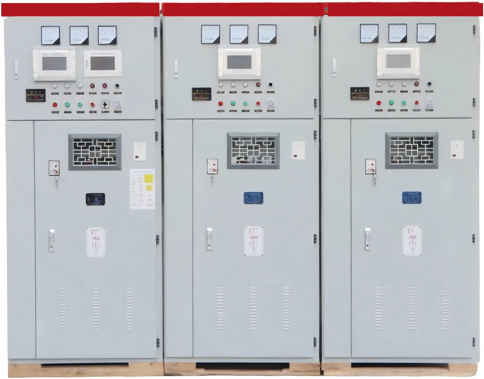
The high-voltage power factor compensation series is the fit when the bank is a medium- or high-voltage shunt installation and the reader still needs the cabinet, not another kvar estimate. HYTBB is the shunt cabinet in that series.
The catalog rates this cabinet at 10(6)–35 kV and 50 Hz, with capacity from 50–20,000 kvar, and the neutral arrangement is isolated-neutral or non-effective-grounding. The lineup includes the capacitors and current transformers a phase-current check depends on, along with reactors and a vacuum breaker.
The line current you calculated is what you compare with the duty of that feeder and those current transformers. It does not replace the catalog kvar range, and the catalog range does not replace the current calculation.
Use the series when the voltage and the neutral arrangement sit inside that published range and the job is shunt reactive power on a distribution bus. Leave it aside when the task is still "how many kvar from this power factor," or when the work is a low-voltage contactor step on a motor control center.
Those are real jobs. They are not this current calculation, and they are not solved by forcing a high-voltage cabinet onto a low-voltage formula result.
FAQ
How do you convert kvar to amps for a three-phase capacitor bank?
Multiply the bank kvar by 1,000, then divide by 1.732 times the line-to-line voltage in volts. The result is supply-lead current at that voltage, with no power-factor term left in the division.
What is the single-phase formula for capacitor current?
Divide kvar times 1,000 by the can voltage in volts. Use this when the fuse or the wire belongs to one can rather than to a three-lead bank total.
Does wye or delta change the supply-lead current?
Not when the kvar you typed is the whole bank and the voltage is the line-to-line voltage. The connection changes the current and the voltage stress inside each can. It does not add a second supply-lead formula.
Should the fuse equal the calculated line current?
The calculated current is the running value. A fuse held to that value alone can open on energizing. Fault level, nearby banks, and harmonic current still have to be faced before a fuse is chosen.
What current should a capacitor-bank CT be able to measure?
The phase current transformer should remain faithful at the running line current of the bank. A primary rating below that current saturates in ordinary service. The calculation does not assign a ratio or a relay setting.
Is calculating capacitor bank current the same as calculating kvar?
No. Current starts from kvar you already have.
Kvar starts from load kilowatts and two power factors. Doing the second job and calling it the first one sizes a bank you have not been asked to size.