
 Zhejiang Hongyan Electric Co., Ltd.





































Wiring a plant or substation bank starts with the voltage each can will see, because that choice fixes every conductor that follows. Capacitor bank wiring decides between a delta connection and a wye, then places the fuse, the neutral sensor, and the discharge device on that same arrangement. A low-voltage stage panel, with its contactor coils and regulator, is a different job from the bank on a medium-voltage bus.
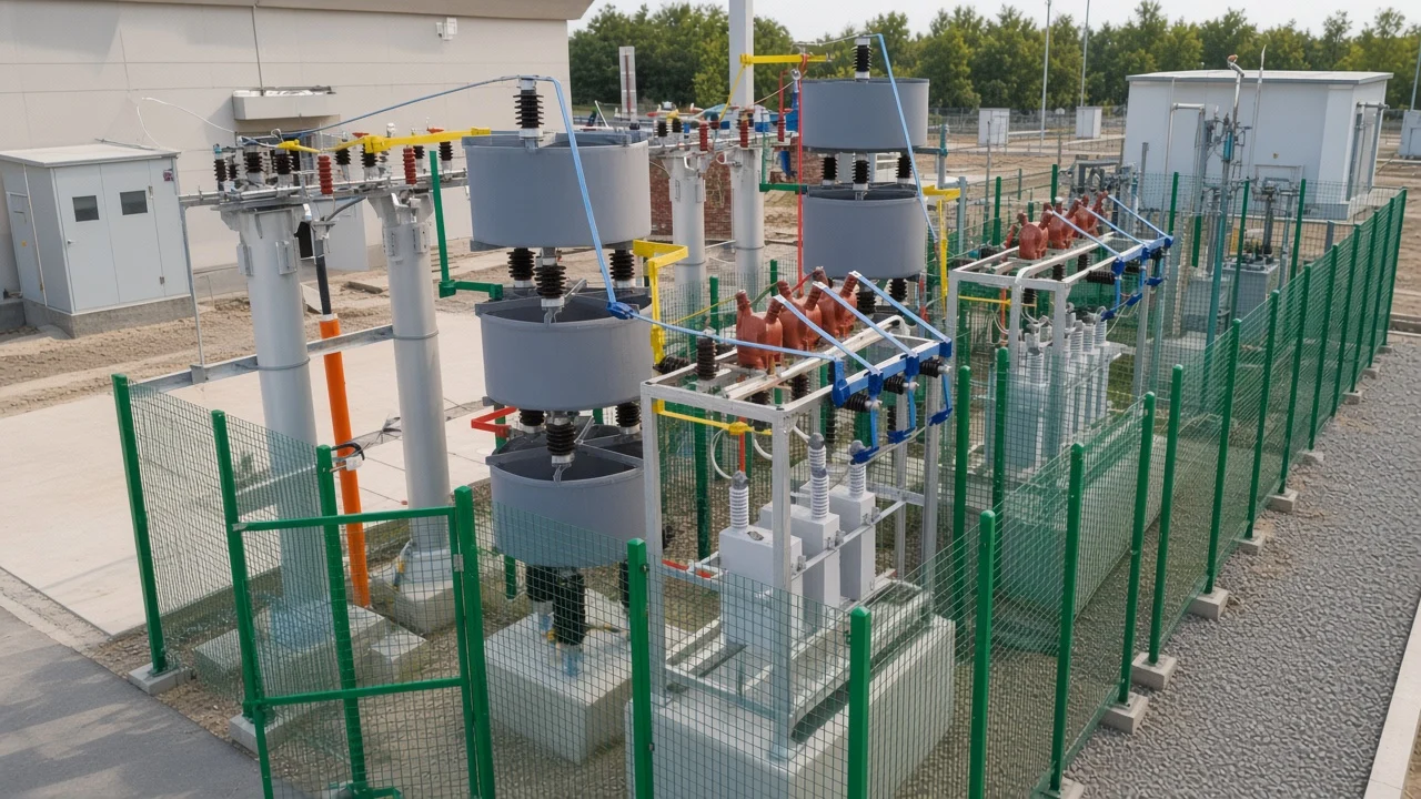
The useful public results for this query spend their length on a panel: an incomer, stage fuses, contactors, and a controller watching one phase. A plant engineer still has to decide whether each can sits phase-to-phase or phase-to-star, and whether the star point is earthed. Those two choices change the fault current and the place an unbalance sensor can work.
Delta or wye sets the voltage on each can
Delta puts each can across two phases, so the can is built for line-to-line voltage. Wye puts each can from a phase to the common star point, so the can is built for phase-to-neutral voltage. Mixing those ratings is how a bank is ordered for the wrong volts before anyone lands a lug.
A delta-connected bank is usually applied at 2400 volts or less. Above that class, line-to-neutral cans in a wye use the capacitor voltage more tightly, and the star point gives you a place to watch balance. Star wiring can also block zero-sequence current that a delta would circulate inside the triangle.
How to wire a capacitor bank at this step is a nameplate check. Read the can voltage, then match it to line-to-line or line-to-neutral. If the cans are line-to-neutral parts, a delta will hold them at the higher voltage for as long as the breaker stays closed.
Inside a high-voltage can, element groups may still sit in series so the string can hold the phase voltage, while the bank as a whole stays in parallel with the inductive load. That internal series string is not the same decision as hanging the whole bank in series with a feeder. The parallel tie is what lets the bank supply reactive current to the bus.
| Connection | Voltage each can should match | What the star point does | Typical sensor later |
|---|---|---|---|
| Delta | Line-to-line | No star point | No neutral current transformer |
| Floating wye | Phase-to-neutral | Floats, and shifts when a can is lost | Neutral-to-ground VT, or a CT between two wyes |
| Grounded wye | Phase-to-neutral | Tied to earth | CT from the neutral to earth |
On a double star, each half still uses phase-to-neutral cans, and the two star points are the measuring points. Connection diagrams for delta, open star, and double star show that split. The plant drawing should name which of those three the bus will actually get.
Fuse position follows the connection, not a panel diagram
The capacitor fuse has to isolate a shorted can before the tank is damaged, and it has to survive normal energizing. A panel sketch that shows one fuse per switched stage does not tell you whether the fuse is outside a delta, inside a delta, or on a wye phase leg. The current it sees changes with that drawing.
On an ungrounded wye, fault current through the incoming fuse is limited by the capacitors in the two healthy phases. The failed can is not fed by the full bus fault level, which is why some substations prefer that arrangement even though the neutral then needs its own sensor. On a grounded wye or a delta bank, that fault current can reach the full short-circuit value of the system, so the fuse and the can have to withstand that current until the fuse clears.
After a failed unit is removed, a continuous overvoltage above 1.1 pu on any remaining unit is the trip concern for unbalance protection. The fuse opening is not the end of the event. The remaining cans on that phase, or on the other phases of a floating star, pick up voltage.
If the unbalance relay is missing or wired to a neutral that does not exist, the crew learns about the problem from the next fuse. The next energizing then becomes the alarm.
From the field: After one fuse opened on a floating wye, the next phase fuse blew as soon as that phase was restored — Mike Holt forum, ungrounded capacitor.
That report was a distribution-line bank whose case was earthed while the electrical star point was left floating. The reply on the thread guessed at a higher can rating and labeled the guess as a guess, so the only lesson carried here is the sequence: one open fuse, then a second fuse on restoration. Treat a single blown fuse on a floating wye as a bank problem, not as a part you replace and re-energize in the same minute.
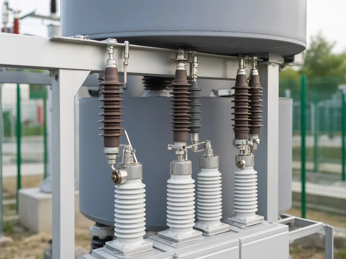
Group fusing and individual fusing also diverge. An individual fuse next to each can can drop one unit and leave the phase in service, which is when the overvoltage concern shows up. A group fuse ahead of a whole phase leg takes the phase off and leaves a larger unbalance for the relay.
Either scheme still has to sit on the connection you built. Copying a low-voltage stage fuse into a medium-voltage rack skips that choice.
Crews also get the supply landing wrong in a more ordinary way. On filled boards, people have landed the bank feed on occupied main lugs with conductors too small for the branch. The bank is a parallel branch with its own disconnect and its own conductors.
It is still a current-carrying circuit when it is on. Sharing a lug with the service conductors does not shrink that current.
Grounded neutral and floating neutral do not share a fault path
Leave the neutral floating and the two healthy phases are the only path into a shorted can. Earth the neutral and a failed can can draw on the system the way a phase-to-ground fault does. The same earthing choice changes lightning behavior: an earthed star gives better protection against transient overvoltages from lightning and against electromagnetic disturbance, and it can also carry zero-sequence current after a can fails or a supply phase is lost.
How to connect capacitor bank neutrals is a protection decision with its own conductor. A floating wye has no intentional ground current in the star point during balanced operation. A grounded wye has a real conductor from that point to the station ground grid, and that conductor is where a current transformer can sit.
Bonding the steel frame and the fence to the ground grid is a separate conductor from the electrical neutral. The Mike Holt case had a grounded case and a floating star at the same time. That pairing is a mechanical ground beside an ungrounded wye.
Third-harmonic current is the other reason the neutral is argued over. An ungrounded star does not offer those currents a path into the system neutral. A grounded star does.
If the bus already carries triplen current from other loads, earthing the bank neutral gives that current another route and puts it through the neutral CT. The relay on that CT has to be tuned so those harmonics do not look like a failed can.
Delta banks avoid the neutral question and take the line-to-line voltage instead. They are the usual fit at the lower voltage class already named. They do not give you a star-point CT.
Unbalance, if you need it, has to be built another way, often by comparing phase voltages rather than by watching a neutral current that the delta does not have. That comparison still has to be drawn on the one-line before the rack is built.
The unbalance CT or VT has to see the neutral you actually built
A grounded wye uses a current transformer on the conductor between the star point and earth. That CT sees the vector sum of the phase currents, and it also sees third-harmonic current, so the relay is tuned toward power frequency. The CT itself needs a high overvoltage and current ability: energizing the bank, especially with another bank already on the same bus, pushes a short heavy pulse through the neutral.
An ungrounded single wye has no neutral current to measure in the ground lead, because that lead is not there. The practical sensor is a voltage transformer from the star point to earth, and that transformer should be rated for full system voltage because the star point can rise during switching.
Three line-to-ground voltage transformers with their secondaries in a broken delta can reject ordinary system unbalance and still show the bank’s own shift. Ungrounded and grounded wye schemes draw both arrangements.
A double floating wye splits the bank into two equal stars and compares them. A current transformer between the two star points, or a voltage transformer between those points, feeds the unbalance relay. System voltage unbalance appears on both halves and cancels.
A failed can on one half does not cancel. This is the scheme that matches a double-star frame. Putting a ground CT on a pair of floating star points will not see the current the scheme is built to measure.
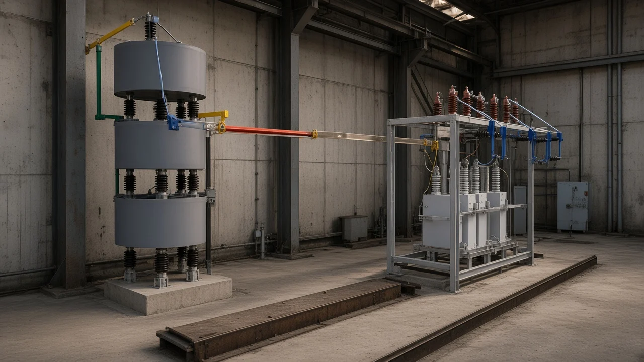
Keep the regulator CT off the unbalance job. The regulator CT belongs on a supply phase so a controller can see load current plus capacitor current. The unbalance CT belongs on the bank neutral, or between two neutrals.
They can both exist on one project. They are not the same core, and landing the neutral sensor on a phase conductor will make a healthy bank look failed, or a failed can look normal.
If the two stars are built with unequal kvar, the current between the star points is no longer a clean sign of a failed can. Balance the two halves on the drawing before the CT ratio is picked. A pre-existing neutral current forces the relay setting up until it is too blunt to see one can.
The discharge path stays across the capacitor after the switch opens
The discharge device stays directly across the capacitor after the bank switch opens. A directly connected discharge device has to bring residual voltage from the crest of rated voltage down to 50 V or less within 1 minute, and no fuse or switch may sit between that device and the capacitor. Opening the bank breaker does not empty the cans.
The discharge device is what does that, and it has to stay connected when every other device in the circuit is open. Pulling that path through a fuse leaves the charge stranded when the fuse opens.
Shorting the terminals together and to earth before anyone handles the cans still comes after the discharge device has bled the voltage. The resistor or coil reduces voltage on a timetable. It does not make the rack safe to touch on a maintenance permit by itself.
The handling step is still a grounded short, applied with the procedures the site already uses for that voltage. The timed bleed and the maintenance short answer two different moments.
On an outdoor frame, the discharge function is often a discharge coil mounted with the capacitor racks, still directly across the groups it serves. If a fuse is placed between that coil and the cans, a blown fuse leaves the charge with nowhere to go. That is the same rule as an indoor resistor: the isolating device that protects the bank from the bus must not isolate the cans from their own discharge path.
How to connect capacitor bank to improve power factor does not move this device. The shunt bank raises power factor by feeding reactive current while it is on. The discharge path is the off-state circuit.
Leaving it out, or switching it with a separate contactor that can be left open, stores the last voltage on the cans until the next close. Closing into a charged bank is a known way to damage the breaker.
The one-minute figure is the residual-voltage target after disconnection. After the bank is switched off, wait at least that minute before switching it on again.
The discharge rule and the grounded-versus-ungrounded fault contrast belong in the same work package. One tells you what stays connected after the breaker opens. The other tells you what the fuse will see while the breaker is still closed.
Which HYTBB connection fits this plant bank
On a substation or industrial distribution bus, the HYTBB outdoor frame works as a shunt bank. Published outdoor-frame ratings are 6–35 kV and 50–60 Hz, with 150–10,000 kvar at 10 kV and below and 600–20,000 kvar at 35 kV. Connection form is part of the order: single-star or double-star, with the protection method chosen to match.
Single-star on that frame is paired with open-delta overvoltage protection. Double-star is paired with neutral-point unbalance protection. That pairing is the same split as the CT and VT discussion above.
A single floating star is watched by voltage. A double star is watched by current between the two neutrals, which is the neutral-point unbalance code. Phase-voltage differential is the other published protection letter when the comparison is between phase voltages rather than a neutral current.
Air-core reactors on this frame sit on the supply side. Iron-core reactors sit on the neutral side. The supply-side reactor is in the phase leads the fuse and the bus see.
The neutral-side reactor is in the star path, so it belongs only on a wye that has that path. Ordering an iron-core neutral reactor for a delta bank asks for a conductor the delta does not have.
| Order code on the outdoor frame | Connection the wiring must match | Protection tie that matches it |
|---|---|---|
| A with K | Single-star | Open-delta overvoltage |
| B with L | Double-star | Neutral-point unbalance current |
| C | Star arrangement named on the order | Phase-voltage differential |
Look to the high-voltage power factor compensation series for the series that holds this frame. Use it when the bus is in the published voltage band and the connection decision is single-star or double-star with the matching protection. It is the wrong object when the task is a low-voltage stage panel, a relay-output diagram, or a pole-mounted unit whose neutral note is a different model.
Power factor still improves only while the shunt bank is connected in parallel and the cans are on the voltage they were built for. The series page is where that frame sits with the rest of the high-voltage compensation line.
Further reading on the protection schemes themselves sits in shunt capacitor bank fundamentals and protection. The separate question of series groups inside a can versus the parallel bus tie sits in are capacitor banks connected in series or parallel. Neither page replaces the landing rules above.
FAQ
How to hook up a capacitor bank on a medium-voltage bus?
Land the three phases on the bank terminals that match the can rating, delta or wye, and give the branch its own disconnect and conductors. Then add the neutral conductor only if the star point is meant to be earthed. The enclosure bond to the ground grid is still required when the electrical neutral floats.
Which wires land on a capacitor can, and which ones must not?
Each can gets the two terminals of its delta leg or its wye leg, plus the discharge device directly across those terminals. A fuse that protects the can from the bus must not be placed between the can and that discharge device. A frame ground is not a substitute for the electrical neutral.
Are the capacitor units in series or parallel with the plant load?
The bank is in parallel with the load so it can supply reactive current to the bus. Series groups inside a high-voltage can only build voltage withstand. They do not put the whole bank in series with the feeder.
What is the right way to connect a capacitor bank neutral?
Earth it when you want the grounded-wye fault path and a neutral-to-ground current transformer, and accept triplen current in that lead. Leave it floating when the healthy cans should limit fault current, and then watch the star point with a voltage transformer or, on a double star, with a sensor between the two neutrals.
When should this bank be wye instead of delta?
Use wye when the cans are phase-to-neutral parts, which is the usual approach once the bus is above the low voltage class where delta is typical. Use delta when the cans are line-to-line parts and you do not need a star-point sensor. The can nameplate, not a panel template, makes that call.
Does connecting a capacitor bank to improve power factor change the discharge wiring?
The discharge device stays directly across the capacitor whether the bank is there for power factor or for voltage support. Improving power factor is what the bank does while the breaker is closed. The discharge path is what remains after that breaker opens.