
 Zhejiang Hongyan Electric Co., Ltd.





































Choosing a synchronous condenser vs capacitor bank has a direct answer: both deal with reactive power, and they are not the same device. The bank is static equipment that supplies capacitive vars for a steady inductive load. The condenser is a rotating, DC-excited synchronous machine with no mechanical load, and it can supply or absorb vars while also adding inertia and short-circuit strength.
Voltage behavior, fault contribution, and losses decide which tool belongs on the project. CHYN sells the shunt cabinet only, so the rotating machine stays a separate specification. A buyer who needs lagging-load correction can stay with that cabinet once inertia and short-circuit strength are off the list.
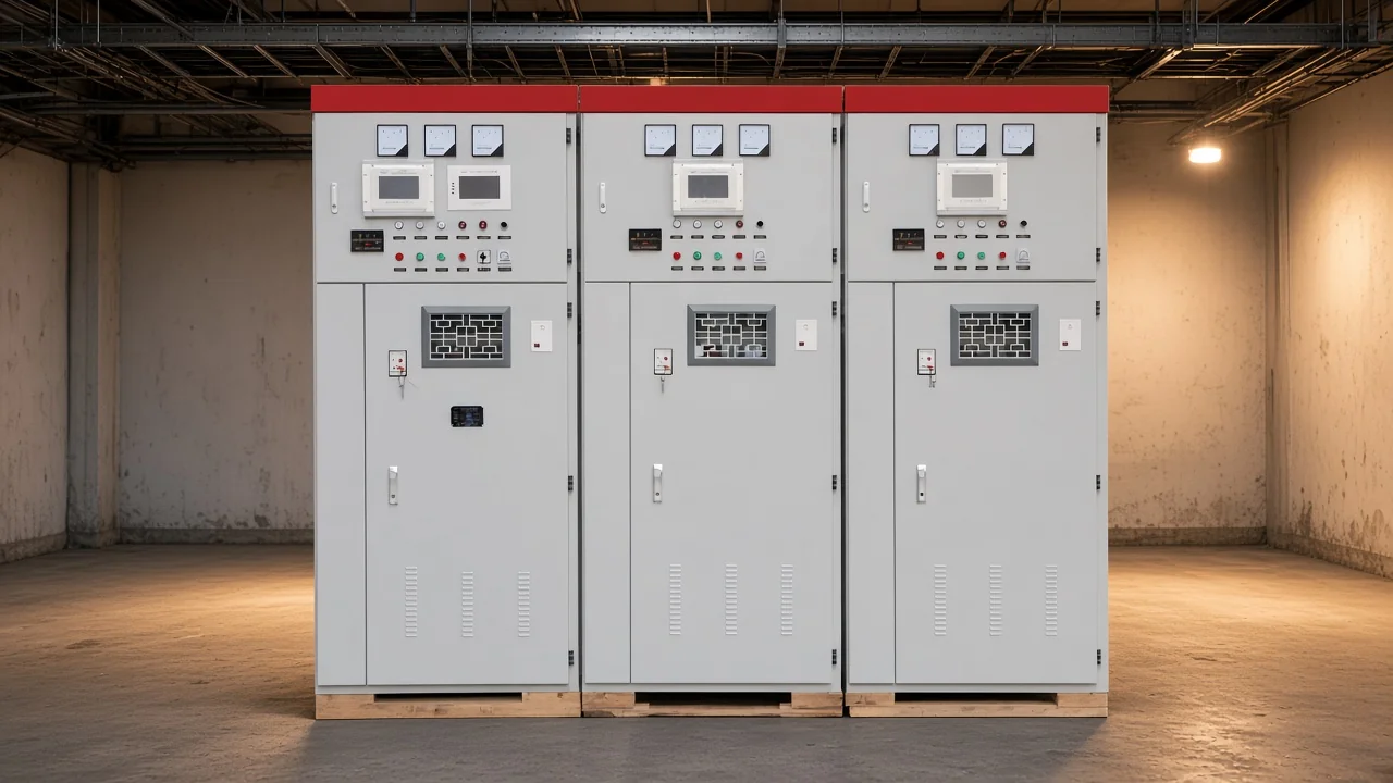
The room view shows the static side of the comparison, a shunt capacitor lineup rather than a spinning machine. Later sections separate var direction, low-voltage output, and the point where the rotating machine becomes the other tool.
What a synchronous condenser is, and what a shunt capacitor bank is
A synchronous condenser is a DC-excited synchronous machine whose shaft is not attached to any driving equipment. A shunt capacitor bank is static equipment connected in parallel with the bus so it can supply capacitive reactive power.
Buyers sometimes see both names on the same one-line diagram and still face two purchases. One purchase is a machine with a field winding, and the other is a capacitor assembly.
Engineers also call the rotating machine a synchronous compensator. Field excitation, the DC field current, moves that machine between lagging and leading output. Nothing in that arrangement stores energy in a dielectric the way a capacitor does.
The shunt capacitor bank has no rotor and no field winding. Buyers meet it as a group of capacitors, often inside a cabinet, sized to feed vars into an inductive plant load.
ENTSO-E’s technology sheet describes the rotating asset as a machine that continuously generates or absorbs adjustable reactive power and contributes short-circuit current. That description is the machine side of the comparison. The cabinet side never grows a shaft.
Name confusion is the first buying error. Older electrical language can use “condenser” for a capacitor, while a synchronous condenser is a machine synchronized to the grid and left without a mechanical load. Treating the cabinet as that machine sends the specification to the wrong equipment class.
How each device supplies or absorbs reactive power
A shunt capacitor bank supplies capacitive vars and does not absorb them. A synchronous condenser can supply or absorb reactive power within the machine’s capability, and the absorb fraction changes with the machine.
Reactive power is the non-working part of apparent power, the portion that supports voltage and magnetizing current. Vars are the unit used when either device is sized, while kilowatts stay a separate quantity.
On a standard machine description in a technical comparison, absorption can reach about half of rated output, while project sheets show other absorb-to-supply ratios. The buying point is the direction of the vars. A single percentage should stay off every nameplate.
Capacitors only push power factor toward unity from a lagging inductive load. If the bus is already capacitive, more capacitors make that surplus stronger. Absorption then belongs to the rotating machine, or to a reactor, rather than to another capacitor step.
| Topic | Synchronous condenser | Shunt capacitor bank |
|---|---|---|
| Var direction | Supplies or absorbs within machine capability | Supplies capacitive vars |
| Voltage behavior | Constant-field output moves with bus voltage | Output follows the square of voltage |
| Inertia | Rotating mass adds synchronous inertia | No rotating mass |
| Short-circuit modeling | Treated as a short-circuit source | Contribution neglected because it decays quickly |
| Losses | Higher active-power losses in published comparisons | Static equipment without that machine loss |
A published laboratory comparison lists inductive capability at 50% to 60% and capacitive capability at 100%. Those figures sit in that comparison table as approximate values for the rotating machine in the study.
What happens to vars when bus voltage falls
Capacitor-bank reactive power follows the square of terminal voltage, so output falls when the bus is already low. Constant-field condenser behavior is a separate textbook description, and a laboratory comparison row uses different wording.
Wikipedia’s synchronous condenser summary states that the reactive power produced by a capacitor bank is in direct proportion to the square of its terminal voltage. A bank that looks adequate at nominal voltage therefore delivers less capacitive support after the voltage has already sagged.
With constant field, that summary says a synchronous condenser naturally supplies more reactive power to a low voltage and absorbs more from a high voltage, and the field can still be controlled. That is the textbook constant-field picture. Keep it separate from the comparison-table row that follows.
The Idaho National Laboratory comparison table lists synchronous-condenser voltage support as decreasing with V, while SVC support decreases with V squared. Read that row as the report’s table entry. It stands beside the constant-field wording, and the two wordings stay unmerged.
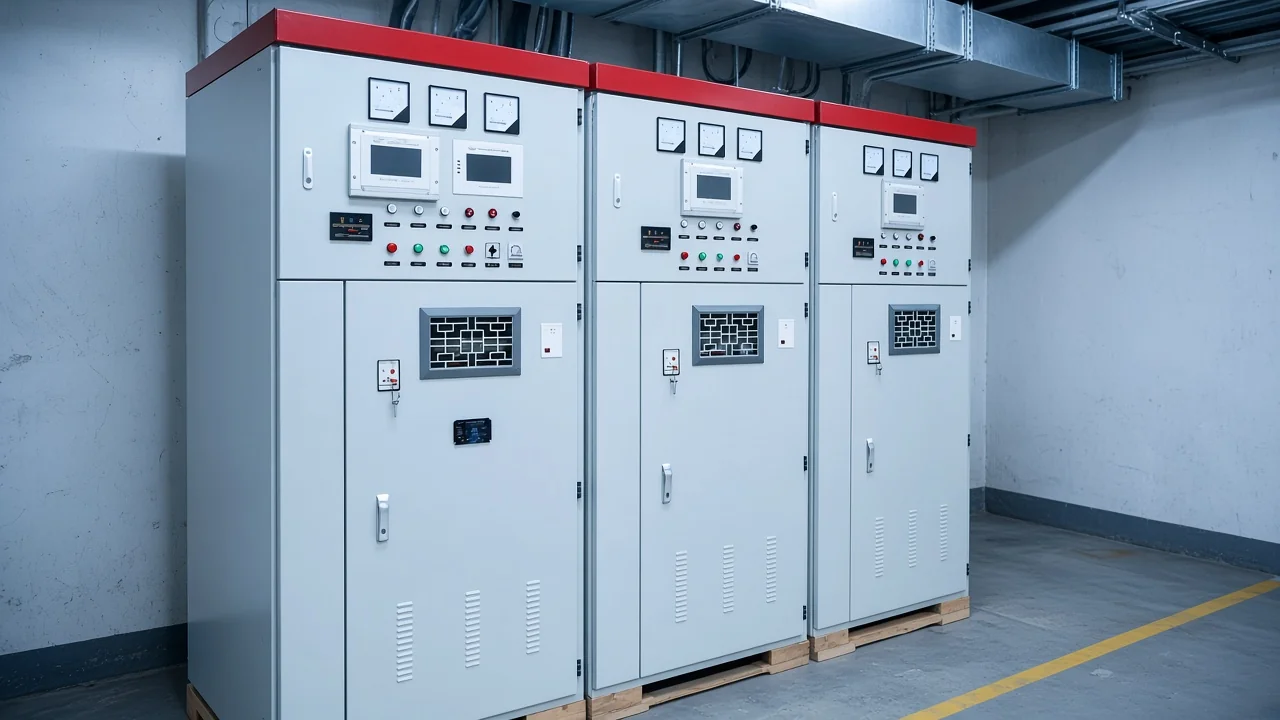
Low bus voltage is the moment a plant hoped the capacitors would help, and the square relationship says their output has already dropped. A rotating machine with field control is the tool specified when that drop is unacceptable and the project can carry a machine.
Where short-circuit strength and inertia change the decision
In the reliability modeling note, synchronous condensers are treated as short-circuit sources, and capacitor contribution is neglected because it decays quickly. Inertia comes from rotating mass, which a shunt bank does not add.
NERC’s short-circuit white paper groups the condenser with synchronous machines for that discussion. Capacitor current leads system voltage by 90 degrees in the paper’s explanation, and the fault contribution is left out of the study because it dies away fast. Protection settings stay outside this modeling note.
Short-circuit strength, also called system strength, is the fault current a synchronous machine contributes in that kind of study. A weak bus or an inverter-heavy plant can need that contribution even when power factor is already acceptable. A shunt capacitor bank sits outside the model that supplies it.
Inertia is the kinetic energy in the rotor that resists a fast change in frequency. Synchronous inertia is the grid-planning name for that rotating-mass effect. A capacitor cabinet has no shaft, so it cannot add that energy.
The INL shunt-FACTS report marks an increase in system inertia for the synchronous condenser. An ordinary switched capacitor bank does not receive that mark. If the specification asks for fault current or inertia, the conversation has left power-factor correction.
When a switched shunt capacitor bank is the practical choice
Use a shunt bank for steady inductive reactive power and power factor correction, with fixed compensation or manual or automatic group switching. Leave that path when the load disappears and the capacitors become the reactive problem, or when inertia and fault current are the real need.
Power factor correction for a lagging load is the everyday case. Motors, transformers, and similar inductive equipment draw vars while they run. A capacitor bank for power factor correction is aimed at that steady demand, not at a machine that must also absorb vars.
Fixed steps suit a load that stays on. Manual or automatic group switching suits a plant whose inductive blocks start and stop in groups. Capacitor banks for reactive power compensation cover that compensation job in more detail.
INL describes mechanically switched shunt capacitor banks as efficient for steady-state voltage support and less effective for dynamic voltage support. A steady inductive load can stay with the bank. A disturbance that needs fast continuous var control moves the specification toward the rotating machine.
A series reactor can sit with the capacitors as an inrush and harmonic reactor. The reactor remains part of the capacitor installation. It stays an accessory on the capacitor steps.
From the field: A Physics Forums user guessed that capacitors already installed on a chiller plant are what appear as the highly reactive load after the chiller shuts off — a user source remark, not a product test.
The leftover-capacitor worry is a user remark about load that has gone away. Fixed capacitive vars do not follow a motor or chiller that has stopped. Switching, or a machine that can absorb vars, answers that objection.
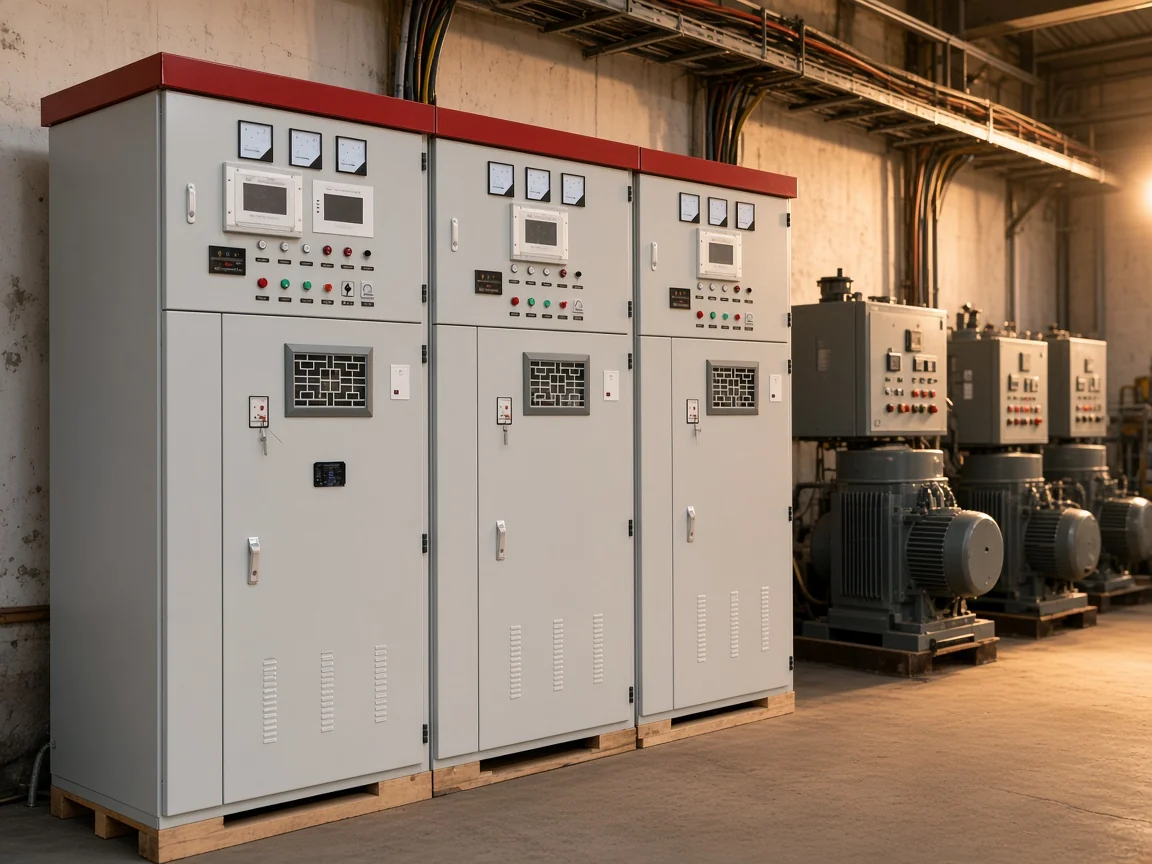
Buyers who already know the load is steadily inductive, with inertia and short-circuit contribution off the list, can treat the shunt cabinet as the practical purchase. Readers who want the plain duty of a bank can continue with what a capacitor bank is used for. The wider family sits in the high-voltage power factor compensation series.
Where the rotating machine is the different tool
Specify a synchronous condenser when the project needs adjustable vars in both directions, short-circuit strength, or inertia. Published comparisons describe higher active-power losses and slower cycle-scale response than power-electronic compensators.
Field current is the control handle on the machine. Raising or lowering field excitation moves the machine from supplying vars to absorbing them without swapping hardware. A capacitor step only adds capacitive output, so it cannot copy that swing.
ENTSO-E describes field forcing of typically 2 to 2.5 times rated field current and voltage for up to 10 seconds on a properly designed unit. Treat that forcing band as a design outcome for a transmission machine. A shunt cabinet does not carry this forcing band.
INL Table 1 lists synchronous-condenser full-load losses at about 3% of full capacitive output and no-load losses at about 1%. Wikipedia’s separate statement puts facility losses near 2–3% of active power. Both point the same way, and neither figure is an energy total.
The same INL table lists typical response at 20 to 30 cycles. That response is slower than the power-electronic rows beside it. Machine voltage in that table is 13.8–25 kV.
Wikipedia places most grid-connected synchronous condensers in a reported 20–200 MVAR band. That band is an encyclopedia statement about machines. It is separate from any cabinet capacity.
One technical comparison often cites up to 2 times rated kvar for up to 10 seconds, and it labels that overload as often available. An example in the same comparison absorbs about half of rated output, illustrated as +25 / −12.5 MVAr on a standard machine. Available ratings in that article run about 10–150 MVAr per machine.
A static synchronous compensator (STATCOM) stays outside this choice, because the decision is the rotating machine versus the shunt capacitor bank. Power-electronic compensators are a different class in the INL report.
Which HYTBB product fits the shunt-bank side
HYTBB fits only after the decision is a shunt capacitor bank. The cabinet is the medium- and high-voltage reactive power compensation cabinet for capacitive vars on a power-frequency system.
The parameter block prints 10(6)–35 kV, 50 Hz, and 50–20,000 kvar. Neutral connection on that block reads isolated neutral or non-effective grounding. The overview also says 1 kV to 35 kV, and those two voltage statements stay separate.
| Item | Cabinet fact |
|---|---|
| Rated voltage in the parameter block | 10(6)–35 kV |
| Rated frequency | 50 Hz |
| Rated capacity | 50–20,000 kvar |
| Neutral connection | Isolated neutral or non-effective grounding |
| Overview voltage sentence | 1 kV to 35 kV |
| Outside this cabinet | Inertia, short-circuit strength, and continuous var absorption |
Open the HYTBB cabinet only after the job is already on the bank side. The photograph below is that cabinet family with the nameplate covered.
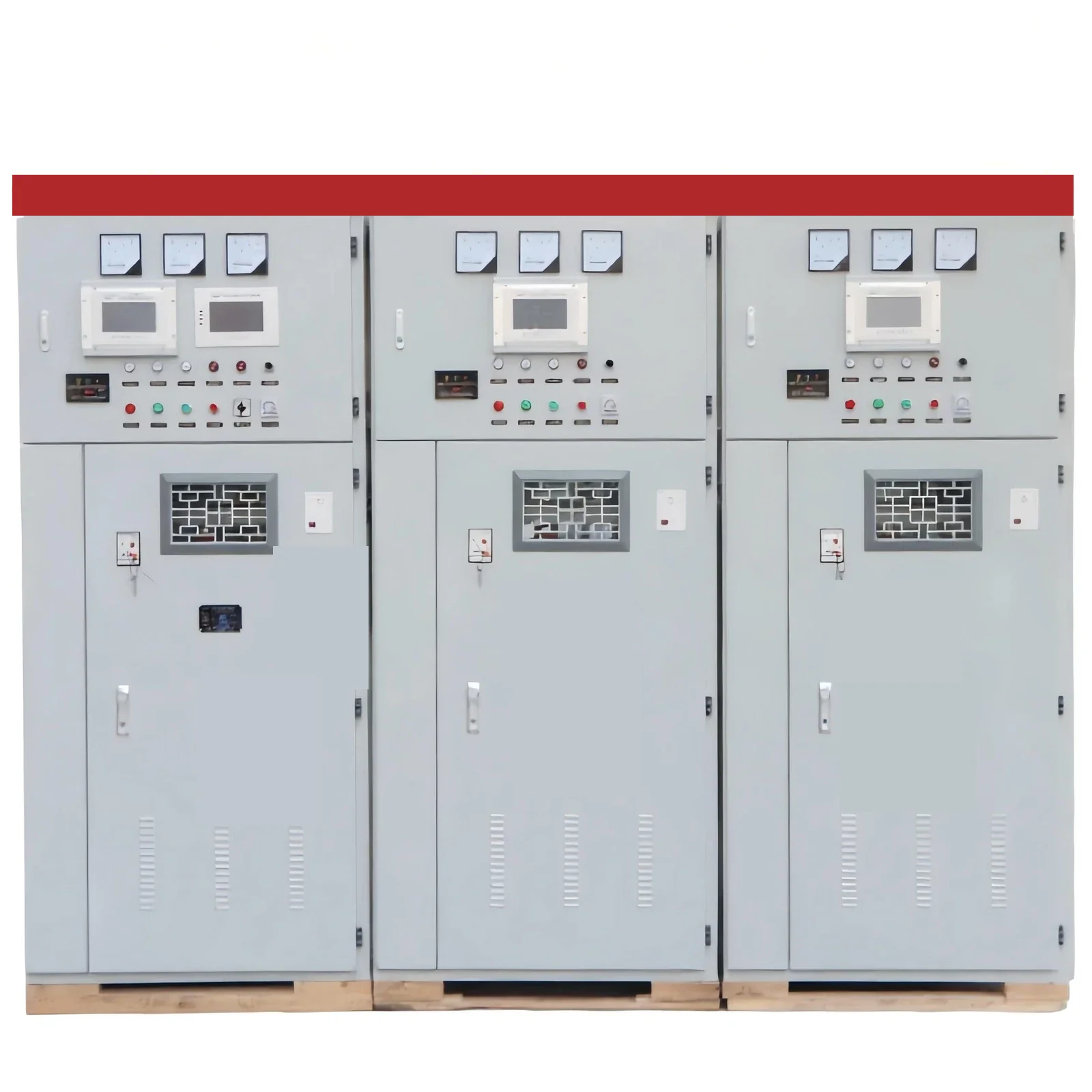
The HYTBB medium- and high-voltage reactive power compensation cabinet is the shunt equipment for this decision, and compensation can be fixed or arranged for manual or automatic group switching. Series-reactor guidance for inrush and harmonic control is 4.5–6% on 6 kV systems and 12–13% on 10 kV systems.
Performance Features says residual voltage drops below 50 V within three minutes. Working Principle item 3 says residual voltage drops below 50 V within five minutes. The project specification has to confirm which interval applies, because both intervals are printed.
HYTBB can reach a power factor of 0.95 or higher, and line current can fall by 10–20%. Ambient range for the cabinet is −40 °C to +45 °C. Relative humidity for the cabinet stays at or below 90% at 25 °C, and altitude stays at or below 4500 m.
Long-term operation is stated at 1.0 times rated voltage, with short-duration withstand up to 1.3 times rated voltage. Indoor and outdoor arrangements are both printed. HYTBB does not add rotor inertia or synchronous short-circuit contribution.
FAQ
Is a synchronous condenser the same device as a capacitor bank?
No. One is a DC-excited synchronous machine with no shaft load, and the other is a static shunt capacitor bank. Shared language around “condenser” does not make the cabinet a rotating machine.
What is the purpose of a synchronous condenser?
The machine supplies or absorbs adjustable reactive power and can add short-circuit strength and inertia. Plants specify it when vars must move both ways or when the grid study asks for a rotating source.
What is the purpose of a capacitor bank?
A capacitor bank supplies capacitive vars to an inductive load and supports power factor correction. It is the tool for that steady capacitive contribution.
When should a project stay with a shunt capacitor bank?
Stay with the bank when the load is steadily inductive and the specification does not ask for inertia or fault-current contribution. Group switching covers blocks of load that start and stop together.
Why does capacitor-bank output fall when bus voltage falls?
Capacitor reactive power follows the square of terminal voltage. A lower bus voltage therefore produces a lower capacitive output from the same bank.
Does a shunt capacitor bank add inertia or short-circuit current?
A shunt bank does not add synchronous inertia, because it has no rotor. In the NERC modeling discussion, capacitor short-circuit contribution is neglected because it decays rapidly.
Can HYTBB absorb reactive power the way a synchronous condenser can?
HYTBB supplies capacitive reactive power as a shunt capacitor cabinet. Absorption of vars remains a condenser or reactor function, so this cabinet leaves that role to the machine.
Is HYTBB a STATCOM or a synchronous condenser?
HYTBB is the shunt capacitor cabinet. The rotating machine is specified separately, and a static synchronous compensator is outside this cabinet.