
 Zhejiang Hongyan Electric Co., Ltd.





































After a plant shunt capacitor bank has been discharged and opened, energizing it means closing it onto the power-frequency bus only after residual voltage has been allowed to fall and grounds and shorts are off. How to charge a capacitor bank in that plant step is the close, not a bench supply brought to the terminals. People who search how to charge capacitor bank usually find a resistor, a bulb, or a constant-current supply, and those steps stay with the small direct-current bank they were written for.
Two cabinet statements stay apart, one for the discharge-circuit design and one for the discharge resistor on each group. Seeing how capacitor bank works on an installed shunt bank starts when the bus, not a battery charger, supplies the charge. The surrounding equipment sits in the high-voltage power factor compensation series.
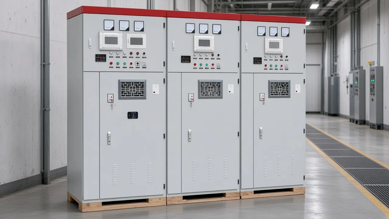
Doors stay shut while the bank waits on the aisle side of the breaker. The next decision is whether residual voltage, cleared grounds, and the close itself are all in place.
What Charging Means for an Installed Shunt Bank
An installed shunt bank is charged by the bus when its breaker closes, after residual voltage has been allowed to fall. That is the plant meaning of charging a bank that has already been discharged and opened.
A parallel capacitor bank sits across the bus and supplies capacitive reactive power toward inductive load. Reconnecting it is a breaker operation, and the charge comes from the power-frequency system the cabinet is built for.
Bench results answer a different object. A hobby pack, a car-audio capacitor, or a supercapacitor string is brought up from a direct-current source before it is used. An installed shunt bank is already the device that will sit on the bus, so the energizing step is the close.
Overview wording places these cabinets on power-frequency systems from 1 kV to 35 kV, and the same wording calls the equipment a shunt capacitor bank. That overview range is the system span. It is kept separate from the rated-voltage cell used later for the cabinet selection.
Why Residual Voltage Remains After the Bank Opens
Stored energy that might endanger personnel has to be released, capacitors in that case are discharged, and capacitors handled during that work are treated as energized. OSHA 1910.333 is the work-practice source for that stored-energy rule and for the later reenergizing order.
After the bank leaves the bus, residual voltage is what remains on the capacitors. In plain language, it is trapped charge left after the switch opens, so an open breaker is not an empty bank.
Hazardous energy remains after the equipment is de-energized, and residual charge may build without an external source. Anyone who then handles those capacitors is still treating them as energized until the stored energy has been dealt with.
While the bank stays open, that voltage falls through the discharge path. The close comes after that fall, and after people and grounds are out of the way.
Keep the Three-Minute Wait and the Five-Minute Wait Apart
One statement belongs to the discharge-circuit design, and the other belongs to the discharge resistors. They are two results on the same cabinet, and neither result is an average of the other.
Performance Features states that residual voltage drops below 50 V within three minutes after disconnection. That line belongs to the discharge-circuit design, and it stands on its own.
Working Principle and Features item 3 states that discharge resistors bring residual voltage below 50 V within five minutes after disconnection. The discharge resistor, also called a bleed resistor in shop talk, is the drain path named for this five-minute result.
A crew that collapses the two results into one clock will follow a sentence the cabinet does not print. Keep each result with the wording that carries it, then read the worker waits in the table as separate rows.
| Statement | What it covers | Printed result |
|---|---|---|
| Performance Features | Discharge-circuit design after disconnection | Residual voltage below 50 V within three minutes |
| Working Principle and Features item 3 | Discharge resistor on each capacitor group | Residual voltage below 50 V within five minutes |
| OSHA 1926.967 | Wait before a worker applies a short | At least 5 minutes after disconnection |
| California §2940.17 | Residual-voltage work rule where that section applies | 50 V or less within 5 minutes, plus at least 5 minutes before the short |
From the field: The construction wait before a worker applies a short, and the California residual-voltage work rule, stay on their own rows and do not replace either cabinet statement — source: OSHA 1926.967 and California Title 8 section 2940.17.
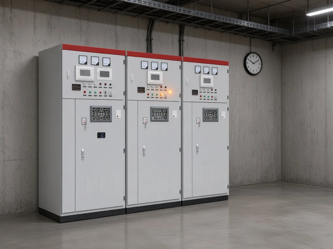
The aisle stays empty while that wait runs its course. Worker rules below are about shorting and grounding, and they do not rewrite either cabinet result.
On construction work covered by OSHA 1926.967, the employee who will apply the short waits at least 5 minutes after disconnection before applying that short. OSHA 1926.967 calls that interval the wait before the short, not the cabinet's three-minute line and not the cabinet's five-minute line.
Where California §2940.17 applies, a means must bring residual voltage to 50 V or less within 5 minutes after disconnection, and the worker still waits at least 5 minutes before applying the short. An internal discharge device does not replace external shorting and grounding before work on the capacitors, under California §2940.17.
Clear Grounds and People Before the Breaker Closes
Tools, jumpers, shorts, and grounds come off, people are warned and clear, and locks come off before the circuit is energized. A crew that still has a ground or a short on the bank does not close into that connection.
OSHA 1910.333 sets that order for reenergizing, including a temporary close. The qualified person checks the removal, people are warned to stay clear, each lock and tag comes off under the rule for who applied it, and someone looks to confirm the area is clear.
From the field: Tools, jumpers, shorts, and grounds come off, exposed people are warned to stay clear, and each lock comes off before the circuit is energized — source: OSHA 1910.333 reenergizing order.
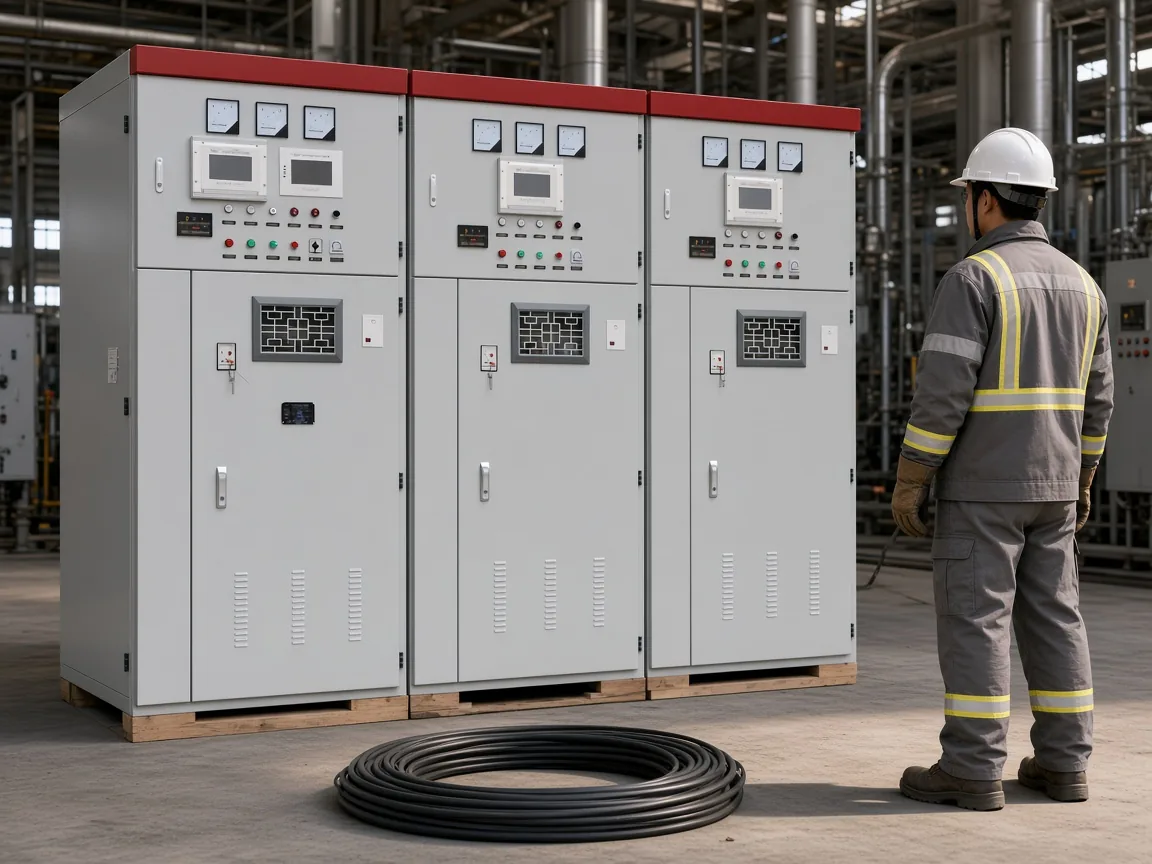
The ground cluster in that scene is off the bus and on the floor. With the cluster clear, the breaker is the remaining switching step.
Closing uses the vacuum circuit breaker already fitted in the cabinet, and group control may be automatic or manual. Discharge resistors are already on each capacitor group, so the close connects a bank that already has its discharge path.
- Tools, jumpers, shorts, and grounds are removed.
- Exposed people are warned to stay clear.
- Locks and tags come off under the rule for the person who applied them.
- A visual check confirms that people are clear.
- Only then is the circuit energized.
What the Close Can Say About Inrush
At connection, the series reactor is the inrush limiter named for the close. Series reactors are stated to limit inrush current and suppress harmonics, typically 4.5–6% on 6 kV systems and 12–13% on 10 kV systems.
At the close, bus voltage meets whatever residual voltage is still on the bank. The reactor percentages stay paired with the system voltages named beside them.
Why a Resistor or Bulb Precharge Does Not Transfer
A series resistor, light bulb, or constant-current charger belongs with a direct-current bank, while this shunt bank takes its voltage from the bus at the close. Public answers for the same search words describe that small-bank precharge.
A car-audio guide tells the reader to precharge to about 11–12 V through 30–1000 ohms or a test light. That guide is the competing procedure, aimed at a car-audio capacitor, and it does not become the plant close.
An ideal series RC circuit charges toward the source voltage with time constant RC, and the initial current is high. HyperPhysics capacitor charging uses that battery, resistor, and capacitor circuit, which is why hobby write-ups put a resistor in series.
One forum thread records a builder asking others to check a homemade charger for safety issues before it is tied to a capacitor bank. That worry, in the EEVblog flyback charger thread, is objection evidence about a builder's project, not a procedure for closing a plant shunt bank.
When the Bank Still Will Not Come In
Overcurrent, overvoltage, unbalanced load, and short-circuit are the named protections. A wait that has already run does not by itself force the breaker to stay closed if one of those protections is asserted.
After the wait, long-term operation is stated at 1.0× rated voltage, and short-duration operation is stated up to 1.3× rated voltage. That pair is an operating ceiling, rather than a calculation of how long the bank takes to charge.
When the close is refused, the useful question is which of those named protections is asserted, or whether the voltage in front of the bank is past the short-duration ceiling. Trip currents and time dials are not printed with those protection names, so none are added here.
Where an HYTBB Cabinet Fits This Close
Use this cabinet when the job is a shunt compensation close and both residual-voltage statements stay intact. For this close, the HYTBB cabinet already includes discharge resistors, a vacuum circuit breaker, and both residual-voltage statements.
Keep that overview span beside the parameter-table cells, rather than folding one into the other.
Rated voltage in the parameter table is 10(6)–35 kV. Rated frequency in the parameter table is 50 Hz. Rated capacity in the parameter table is 50–20,000 kvar.
Neutral connection in the parameter table is isolated neutral or non-effective grounding. Stated compensation outcome is a power factor up to 0.95 or higher, with line current reduced by 10–20%.
| Printed cell | Value kept separate |
|---|---|
| Overview system voltage | 1 kV to 35 kV |
| Parameter-table rated voltage | 10(6)–35 kV |
| Parameter-table rated frequency | 50 Hz |
| Parameter-table rated capacity | 50–20,000 kvar |
| Neutral connection | Isolated neutral or non-effective grounding |
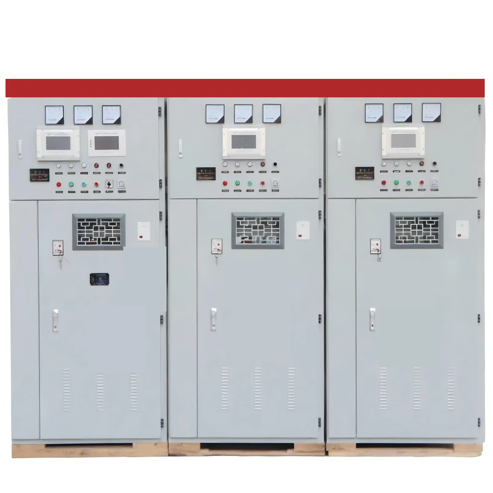
The photograph shows the cabinet with the nameplate covered, which is the product in front of this close. Compare the two residual-voltage statements and the cells above with the plant procedure before selecting it.
The HYTBB medium and high voltage reactive power compensation cabinet is the shunt cabinet that carries both residual-voltage statements into the close.
A car-audio precharge, a hobby bench charger, and a supercapacitor string are different jobs. The site work procedure still governs the close.
FAQ
How do you charge a shunt capacitor bank after it has been discharged?
Let residual voltage fall, clear grounds and shorts, and then close the bank onto the bus. Keep the discharge-circuit wait and the discharge-resistor wait as two separate results.
Why are there both a three-minute and a five-minute residual-voltage line?
One line is the discharge-circuit result, and the other is the discharge-resistor result. Treating them as one clock would drop one of the two statements.
Does a 12 V resistor or test-light charge apply to this cabinet?
The resistor or test-light step stays with the audio capacitor, and it does not become the plant close.
How do you tell whether the bank is still charged before the close?
Look at residual voltage still on the bank, not at an audio precharge display. A university laboratory note says discharge to 50 V or less must not take longer than 5 minutes, and must not take longer than the time to reach the terminals. Virginia Tech capacitor safety also notes that grounding capacitors in series may transfer stored charge instead of removing it.
Can the bank be closed while a ground or short is still applied?
No. Tools, jumpers, shorts, and grounds come off, people are warned, locks come off, and people are confirmed clear before the circuit is energized.
Why might the close be refused even after the wait?
Overcurrent, overvoltage, unbalanced load, and short-circuit are the named protections. The operating ceiling above is not a second charge timer.
Are series supercapacitors that "do not charge up evenly" the same problem?
No. That wording is a low-voltage series-string complaint, and it is not the close of a plant shunt bank.