
 Zhejiang Hongyan Electric Co., Ltd.






































An internally fused capacitor bank is built from capacitor units in which each capacitor element has a dedicated fuse sealed inside the unit case, so a failed element can be isolated while remaining parts of that unit and the bank may continue within design limits — unlike an externally fused scheme that removes a whole unit at the terminals, or a fuseless construction where a failed element typically shorts its parallel group. The operated fuse usually stays hidden inside the sealed can, so unbalance protection and capacitance records matter more than a rack-visible link. Internal fuses do not replace the bank circuit breaker, and the HYTBB pathway that follows is a shunt-cabinet read outside any fuse-scheme claim.
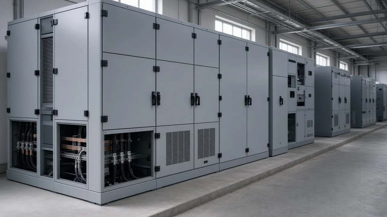
What an Internally Fused Capacitor Bank Means at the Element
An internally fused capacitor bank uses units in which each protected capacitor element has a fuse sealed inside the case, so a failed element can be isolated while remaining parts of that unit and the bank may continue within design limits.
The capacitor element is the series or parallel building block inside the unit that the internal fuse protects. In plain language, it is the small part inside the can that can fail while the rest of the pack may stay useful.
The capacitor unit (can) is the sealed assembly that holds many elements. Field work replaces that sealed can when internal fuses accumulate; it is not an element-level field repair.
The internal fuse (IEC 60871-4) isolates faulty capacitor elements so remaining parts of that capacitor unit and the bank can operate. That standard object is the element fuse inside the case, unlike a visible rack link.
Educational taxonomy puts a small fuse with each protected element, notes that voltage rises on remaining elements in the affected group, and treats the sealed unit as the field-replaced item because the failed element is not normally visible.
When a buyer asks what “internally fused” names before an RFQ, the answer locks at that element-inside-unit layer. The label does not, by itself, name the bank breaker, the outdoor cabinet style, or a fuse-ampacity worksheet.
How an Externally Fused Capacitor Bank Differs at the Unit Terminals
An externally fused scheme places a fuse outside the capacitor unit so the intended removal is the whole can; a blown fuse is often visible, and losing one unit is a larger unbalance or voltage step than clearing one internal element.
An externally fused capacitor bank therefore answers a different failure step. The fuse lives at the unit terminals or on the rack, and the walkdown often starts with that open link.
| Construction | Fuse location | What fails or is removed | Walkdown visibility | Typical field replacement |
|---|---|---|---|---|
| Internally fused capacitor bank | Fuse per capacitor element inside the sealed unit | Failed element is isolated; unit and bank may stay in service within design limits | Operated fuse usually not visible | Replace the sealed capacitor unit (can) after cumulative element losses |
| Externally fused capacitor bank | Fuse at unit terminals or rack | Whole capacitor unit is removed | Blown fuse often visible on the rack | Replace or reconnect after the unit fuse clears |
| Fuseless capacitor bank | No internal element fuse and no individual external unit fuse in that sense | Failed element typically shorts its parallel group | No blown element or unit fuse to inspect | Follow series-path stress and unbalance limits; no fuse-link swap |
That table is the scheme contrast only. It does not size fuse links, and it does not retell a full fuseless-bank deep dive.
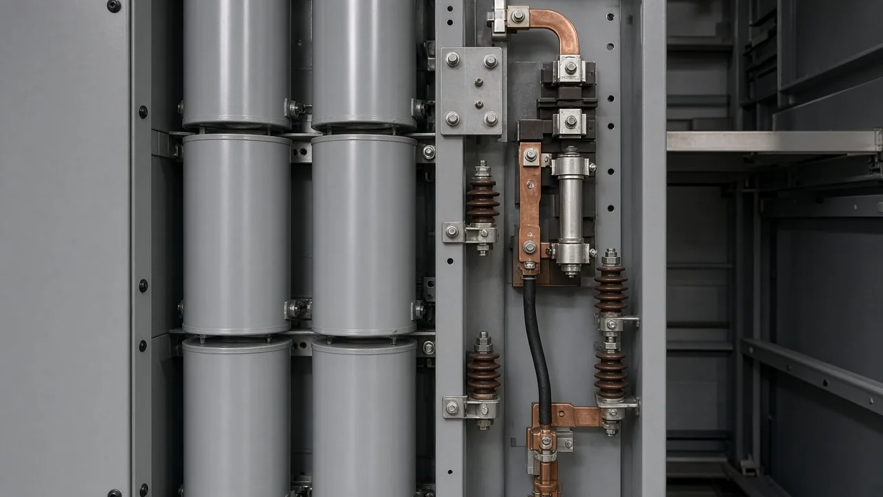
How a Fuseless Capacitor Bank Differs When an Element Fails
In fuseless construction there is no internal element fuse and no individual external unit fuse in that sense; a failed element typically shorts its parallel group and raises stress on the remaining series path — a different failure path from an internal fuse that opens the failed element.
A fuseless capacitor bank therefore follows a shorted-element series-path stress model. The stress moves along the remaining series path rather than opening a dedicated element fuse inside the can.
Fuseless scheme language belongs here only as that short contrast. The longer plant-bus story stays on the sibling fuseless article.
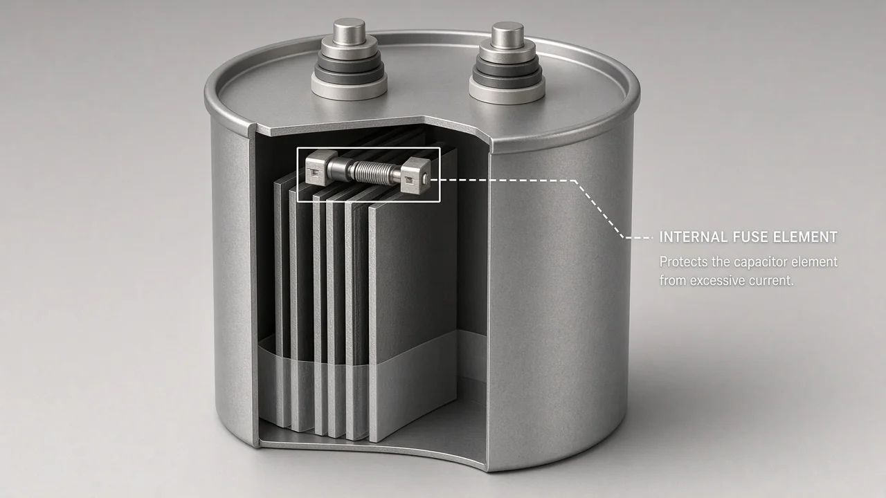
The element-fuse scene belongs with that three-way scheme contrast, not with a fuse-ampacity worksheet.
What Happens When an Internal Fuse Operates
After an internal fuse clears a failed element, voltage on the remaining parallel elements in that group rises; the operated fuse is sealed inside, so detection usually depends on unbalance sensing or capacitance records rather than a rack-visible link.
Remaining elements in the affected parallel group see higher voltage after that clear. Unbalance protection is what watches the accumulating element losses when those fuses stay hidden.
From the field: Plant language often mixes “internal” can fuses with unit or bank fuse sizing, and capacitors may still test okay after an internal path operated — Mike Holt — failed capacitor resistors.
That thread is location clarity, not an ampacity table. Eng-Tips threads ask the same location-versus-sizing question when someone says “internal” and then reaches for a link chart.
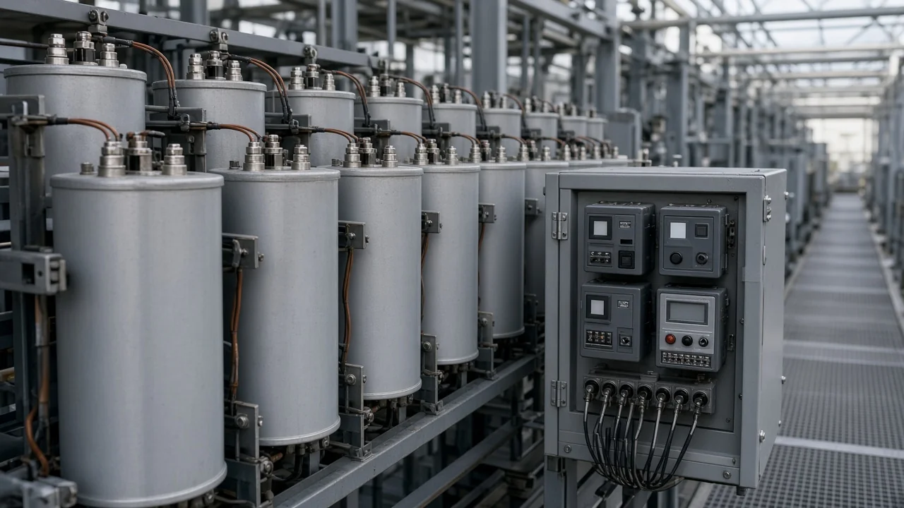
Sensitive unbalance relaying and neutral unbalance methods appear here only as why hidden element losses still need sensing. This section does not teach a relay-scheme catalog.
What Internal Fuses Do Not Replace on the Bank
Internal fuses isolate faulty elements and do not replace the bank circuit-breaker or external bank protection; no fuse-link sizing table is published here.
IEC 60871-4 states that such fuses do not replace a switching device such as a circuit-breaker, or external protection of the capacitor bank. The element fuse clears the bad section inside the can; bank switching and external bank protection stay separate jobs.
Industry protection guidance for shunt capacitor banks is collected in IEEE C37.99 as a guide; check the current catalog status before treating any edition as active. That catalog mention is scope language only for edition status on the guide page.
Someone who treats element fuses as a breaker substitute will miss the switching device that still has to open the bank. The boundary is location and duty; it stops short of a second fuse chart.
How to Choose a Next-Step HYTBB Solution After the Fuse-Scheme Lesson
Choose the HYTBB medium and high voltage reactive power compensation cabinet when the next step is a printed shunt capacitor bank pathway for inductive reactive-power compensation on power-frequency systems — and ask the supplier which capacitor-unit fuse arrangement applies, because the page does not state an internally fused, externally fused, or fuseless construction.
The HYTBB series reactive power compensation cabinet is designed for power frequency systems with rated voltages from 1 kV to 35 kV. It functions as a shunt capacitor bank that compensates for inductive reactive power in the system.
Rated voltage in the parameter table is 10(6)–35 kV. Rated frequency is 50 Hz. Rated capacity is 50–20,000 kvar.
Neutral connection is printed as isolated neutral or non-effective grounding. Isolated neutral is one phrase. Non-effective grounding is the other phrase, kept beside it rather than folded into one grounding name.
| Printed HYTBB row | Keep as |
|---|---|
| Overview voltage | 1 kV to 35 kV |
| Parameter-table voltage | 10(6)–35 kV |
| Rated frequency | 50 Hz |
| Rated capacity | 50–20,000 kvar |
| First neutral phrase | Isolated neutral |
| Second neutral phrase | Non-effective grounding |
| Residual voltage, performance features | Below 50 V within three minutes after disconnection |
| Residual voltage, discharge resistors | Below 50 V within five minutes after disconnection |
| Named protections | Overcurrent, overvoltage, unbalanced load, and short-circuit protection |
| Fuse scheme | Not printed |
Residual voltage drops below 50 V within three minutes after disconnection on the performance-features discharge-circuit line. Residual voltage drops below 50 V within five minutes after disconnection on the working-principle discharge resistors of each capacitor group.
Those two residual-voltage times stay separate. Do not average them into one wait clock.
Protection wording lists overcurrent, overvoltage, unbalanced load, and short-circuit protection. Unbalanced load on that list still does not name a capacitor-unit fuse scheme.
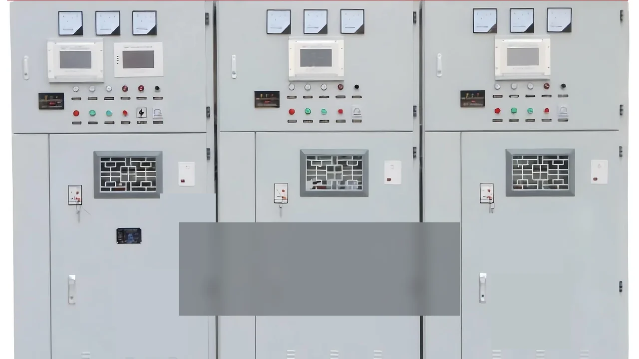
Readers who need neighboring compensation types can open the high-voltage power factor compensation series. Product detail sits on the HYTBB medium and high voltage reactive power compensation cabinet page only as that printed shunt-cabinet job.
What Stays With the Fuseless, Unbalance, and Fundamentals Articles
The sibling edge leaves out the fuseless-bank deep-dive, the unbalance-protection watch, or shunt fundamentals and outdoor-cabinet framing; those URLs remain lateral boundaries only.
Keep the series-string fuseless story on fuseless capacitor bank. Keep relay-scheme detail on capacitor bank unbalance protection. Keep breaker, overcurrent, and discharge fundamentals on shunt capacitor bank fundamentals and protection.
The job that remains here is the element-inside-unit naming lesson, the external and fuseless contrasts, the hidden-fuse behavior boundary, and the honest HYTBB shunt-cabinet next step.
FAQ
What does an internally fused capacitor bank mean?
It means a shunt bank built from units that place a fuse with each capacitor element inside the sealed case. A failed element can be isolated while remaining parts of that unit and the bank may continue within design limits.
How is an internally fused capacitor bank different from an externally fused capacitor bank?
An externally fused capacitor bank places the fuse outside the unit so the intended removal is the whole can. The externally fused scheme often leaves a visible blown fuse and a larger capacitance or voltage step than clearing one internal element.
How is an internally fused capacitor bank different from a fuseless capacitor bank?
A fuseless capacitor bank has no internal element fuse and no individual external unit fuse in that sense. A failed element typically shorts its parallel group and raises stress on the remaining series path, instead of opening an element fuse inside the can.
Can the bank keep running after one internal fuse operates?
Often yes, within the design’s remaining-element and unbalance limits. Voltage on the remaining parallel elements in that group rises after the clear, so sensing still matters.
Why can’t I see which internal fuse operated?
The operated fuse is sealed inside the capacitor unit (can). Detection usually depends on unbalance protection or capacitance records rather than a rack-visible link.
Do internal fuses replace the bank circuit breaker?
No. Internal fuses isolate faulty elements and do not replace the bank circuit-breaker or external bank protection.
Does HYTBB specify an internally fused construction?
No. HYTBB prints shunt-cabinet rows such as 50 Hz, the voltage and capacity ranges, isolated neutral and non-effective grounding as two phrases, and unbalanced load among named protections, without stating an internally fused, externally fused, or fuseless construction.