
 Zhejiang Hongyan Electric Co., Ltd.
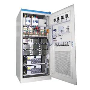
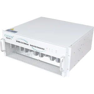
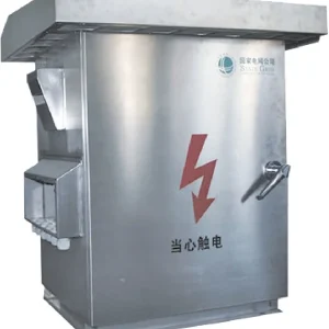
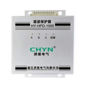
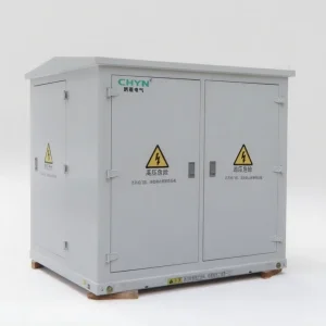
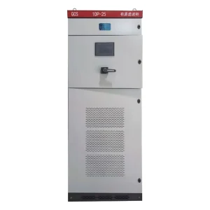
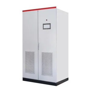
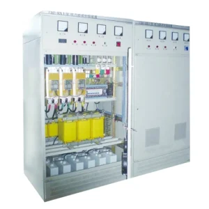
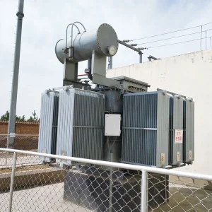
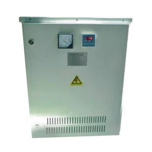
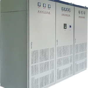
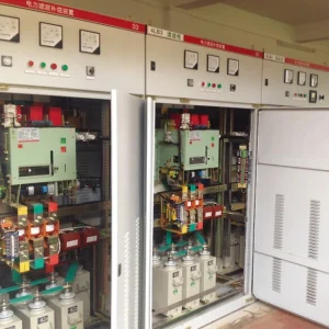
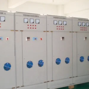
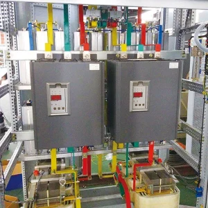
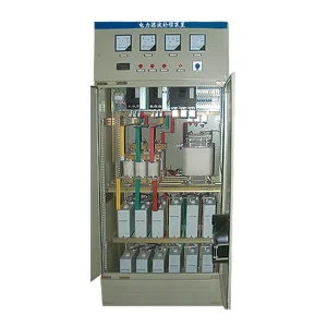
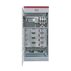
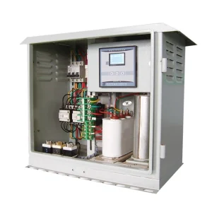
A dynamic voltage restorer can compensate a voltage swell only when its converter, series injection path, controls and energy-handling arrangement support that duty. A unit selected for voltage sag mitigation should not automatically be assumed to handle every overvoltage event. Start with recorded event magnitude, duration, phase pattern and load behavior, then ask the supplier to confirm the permitted swell envelope and the destination of any absorbed energy. The acceptance test must demonstrate the complete operating sequence, including recovery and any transfer to bypass, under the agreed conditions.
Define the event before selecting equipment
Describe the recorded disturbance rather than using overvoltage as a catch-all term. A temporary rise in RMS voltage, a fast transient impulse and a sustained supply regulation problem require different assessment. Capture phase voltages and timing, and state how the instrument calculates RMS values. Include the protected equipment's actual response: a trip, control reset, alarm or continued operation.
Check where the measurements were taken. An event at the service entrance may differ from the voltage at the sensitive load terminals. Record transformer taps, capacitor switching and major load changes with the waveform files. These records help identify the cause and establish the conditions that the mitigation system must withstand.
The broader guide to custom power devices provides context for choosing a series compensation approach. The present assessment concerns swell capability specifically, rather than replacing the complete site power-quality study.
Understand what series voltage injection must achieve
A DVR changes the load-side voltage by inserting a controlled series voltage. Conceptually, the required injected voltage is the desired load-voltage phasor minus the source-voltage phasor. During a simple balanced swell with no phase change, that means a voltage opposing part of the source voltage. An unbalanced event or phase-angle change makes the requirement more complex.
As an illustration, assume a 230 V phase-to-neutral target and a source that rises to 253 V with unchanged phase. The simple phasor difference is minus 23 V: an opposing series contribution is required. This arithmetic is only an idealized steady-state voltage example. It does not size the converter, transformer or energy storage, nor establish transient response or zero-sequence capability.
All values in that illustration use the same phase-to-neutral basis. Mixing a line-to-line rating with a phase voltage can lead to a wrong requirement. Ask the supplier to state the voltage reference, connection and injection limits for each event category rather than accepting a single unexplained percentage.
Ask where the energy goes during a swell
Voltage capability is one part of the assessment. Depending on the compensation method and load current, the series converter may need to absorb real power while reducing the load voltage. That energy needs a supported destination. Different architectures can handle it differently, so a storage-capacity statement alone is insufficient.
Ask whether the proposed arrangement can return energy, store it within permitted limits, dissipate it through an approved path or use a control method with different power exchange. Request the operating restrictions and protective response. Do not assume that an energy-storage device is ready to accept energy merely because it has enough energy to support a sag.
A research review of DVR topologies and controls describes differing power circuits, compensation methods and storage arrangements. This variation is the reason to request architecture-specific evidence rather than treating the letters DVR as a universal swell guarantee.
Specify a swell duty matrix
| Event feature | Information to provide | Supplier confirmation required |
|---|---|---|
| Voltage rise | RMS magnitude and voltage basis at the connection point | Supported injection envelope for the proposed model |
| Duration and repetition | Event length, spacing and expected sequence | Energy and thermal capability across the sequence |
| Phase pattern | Balanced or unbalanced event, including phase changes | Control and transformer connection compatibility |
| Load condition | Current, power factor and possible regeneration | Permitted power flow and current limits |
| Outside-envelope event | Required behavior when compensation cannot continue | Protection, bypass and load consequence |
This matrix defines information requirements, not universal acceptance limits. Set actual tolerances from the load requirements, the reviewed equipment design and applicable project criteria. Keep separate acceptance rows for conditions that the supplier excludes, so nobody mistakes an untested event for a covered duty.
Do not transfer a research prototype's results to a purchased system
The University of Puerto Rico hosted teaching material on filters and DVRs presents series compensation examples, including a three-phase event with both reduced and increased phase voltages. Such educational examples explain the compensation task. They do not establish the ratings, protective behavior or energy-handling capability of a purchased system.
When reviewing a supplier report, identify the actual hardware, power source, load and event generator. Determine whether the evidence is simulation, laboratory testing or a test of the proposed commercial model. Each form can be useful, but they answer different questions. A simulated waveform cannot confirm a production unit's protective coordination or repeated-event thermal performance.
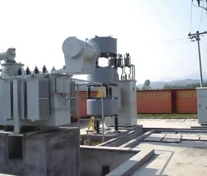
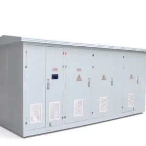
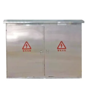
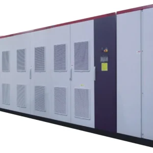
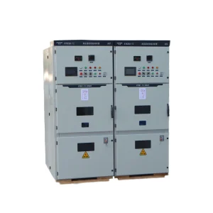
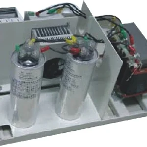
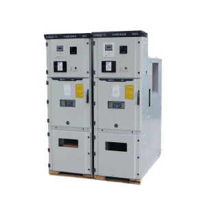
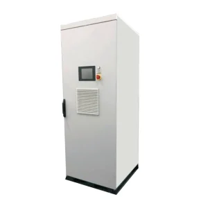
Require any extrapolation to a different power level or connection to be explained by the responsible designer. The enclosure photograph and a general product brochure cannot fill that gap. Keep the supporting report linked to the exact technical offer and its stated exclusions.
Review bypass and load continuity explicitly
A bypass arrangement can protect the DVR or enable maintenance, but its operation may expose the load to the incoming supply. The transfer sequence therefore matters when the source voltage is already above the load's acceptable range. Ask what happens at the boundary of compensation capability, during an internal alarm and after a protection trip.
Agree the required output behavior and the consequence of a transfer before ordering. Some processes can tolerate a controlled shutdown; others require a different system architecture or upstream correction. The technical evaluation should make this choice visible instead of assuming that bypass means uninterrupted protection against every disturbance.
Use the complementary DVR bypass and protection guide to document the transfer paths. Keep those requirements in the swell duty matrix so the acceptance procedure covers the operating boundaries as well as successful compensation.
Prepare an acceptance test with safe event generation
Develop the procedure with the manufacturer and qualified test personnel. Use suitable test equipment and a reviewed setup; do not create an uncontrolled supply overvoltage on a live production system. Specify the source event, load state, measurement channels and abort conditions before energizing the test arrangement.
Record synchronized source voltage, load voltage, load current, converter status and the energy-system variables available through approved monitoring. Synchronize channels closely enough to interpret entry into compensation, steady operation and recovery. Include the waveform files rather than providing only screenshots or a final pass label.
Repeat the agreed sequence where repetition is part of the duty. Establish the initial operating condition and permitted recovery time between events. A single successful event from an ideal initial state does not demonstrate repeated operation after earlier disturbances. Note alarms and protective transitions even when the load stays inside its voltage tolerance.
The DVR acceptance-test workflow can support the documentation structure. Add swell-specific cases and energy-path checks rather than reusing a sag-only test sheet unchanged.
Relate the enquiry to CHYN equipment carefully
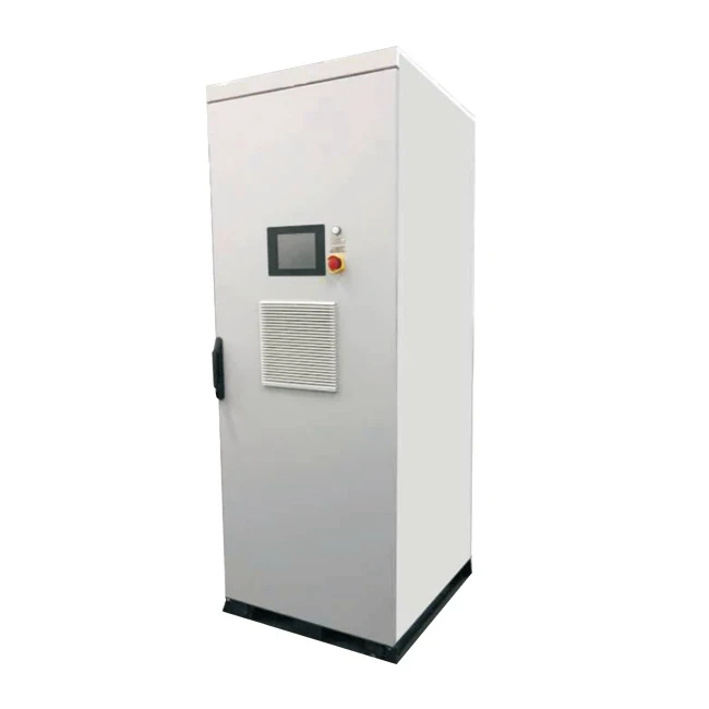
The CHYN HYDVR product family is presented for voltage-sag mitigation. Its presence in this article identifies the relevant product enquiry, not verified voltage-swell capability for every model. Obtain written confirmation for the recorded swell duty, connection and load before selecting an option.
Send the single-line diagram, voltage recordings, load tolerance, operating current, event repetition and required behavior outside the compensation envelope. Ask for the offered model's architecture, energy-handling restrictions and proposed test evidence. Include installation access and service requirements so the final selection fits both electrical and operational needs.
Where the supplier cannot confirm the required envelope, revisit the mitigation approach with the project engineer. Investigating the upstream cause, changing regulation arrangements or choosing another protection architecture may be appropriate. Do not resolve an unsupported swell requirement by relabeling a sag product or increasing its kVA without a design review.
Educational background
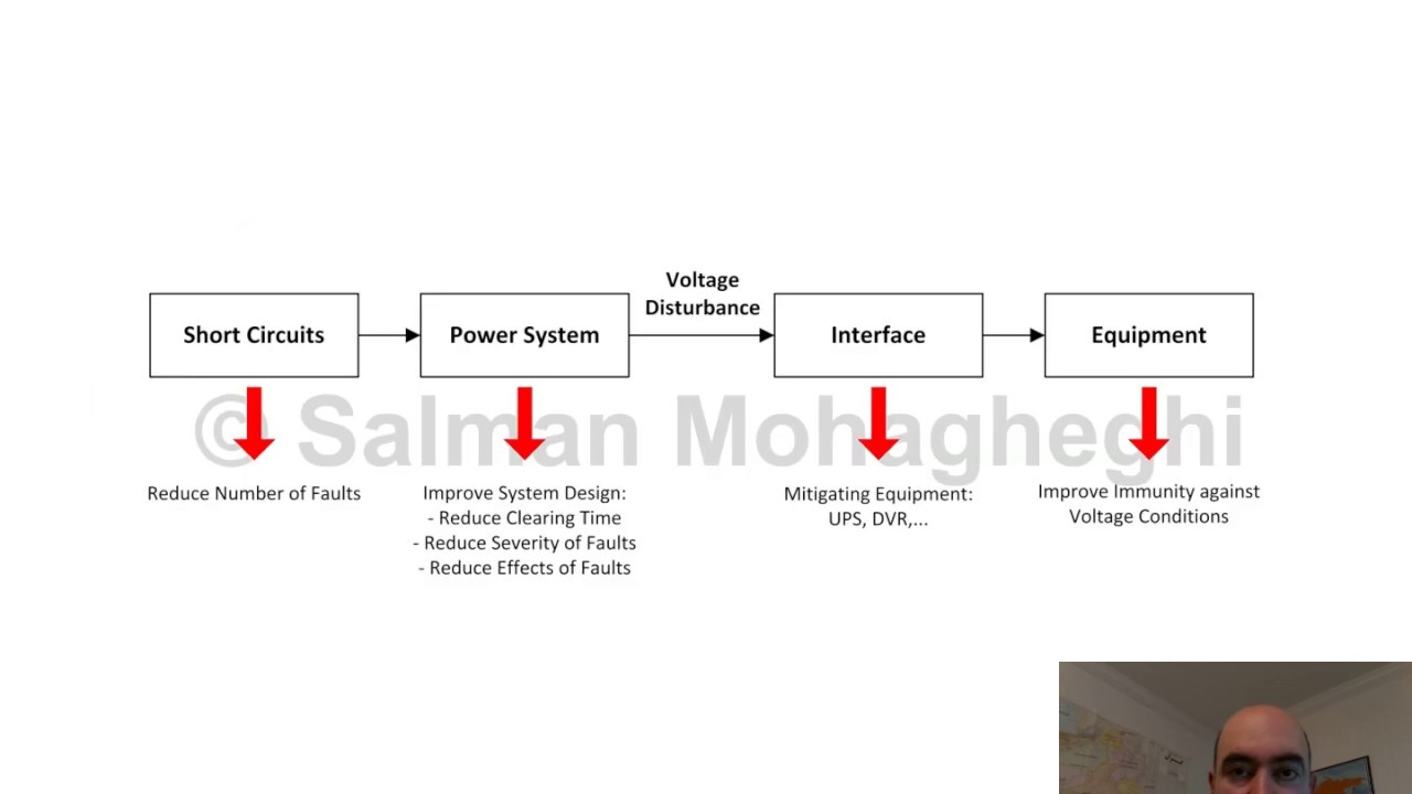
The following university lecture introduces mitigation of sags and interruptions, providing background on voltage disturbance protection. It does not establish swell capability. Use it to understand why protection duties and operating limits must be specified separately, then rely on the model-specific evidence described above for the swell decision.
Watch the educational lecture on YouTube.
Frequently asked questions
Can every dynamic voltage restorer compensate a voltage swell?
No. The proposed converter, series path, controls and energy handling must support the required event. Confirm the model-specific envelope instead of inferring it from sag capability.
Why does energy handling matter when the voltage is too high?
Some compensation strategies can require absorption of real power while reducing load voltage. The equipment must provide a supported destination for that energy and remain within its operating limits.
Is a swell the same as a fast surge?
No. Record the event waveform and duration. A DVR swell assessment does not establish protection against every fast transient or sustained supply problem.
What should the acceptance test demonstrate?
It should demonstrate the agreed source event, load-voltage response, energy handling, recovery and protective behavior, including repeated events and operating boundaries where those form part of the specification.