
 Zhejiang Hongyan Electric Co., Ltd.
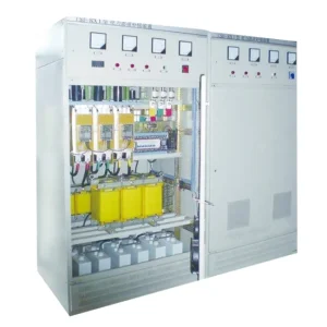
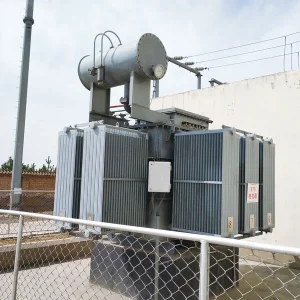
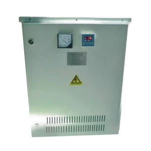
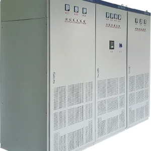
A soft starter with a long motor cable needs two separate reviews: whether the motor receives enough voltage and accelerating torque, and whether the starter can tolerate the cable's electrical characteristics. Cable length alone is not a selection rule. Give the starter supplier the actual route, cable construction, parallel circuits, motor data and starting duty. Obtain written approval for the complete arrangement before installation. This guide explains the information and acceptance evidence to prepare for a medium-voltage solid-state starter; it does not assign a universal maximum cable length or transfer another manufacturer's limits to CHYN equipment.
Define the complete starting circuit
Begin with an accurate route from the supply transformer to the motor terminals. Include upstream feeder sections, switchgear, starter, joints, terminal boxes and every parallel cable run. Distinguish the starter's incoming cable from the outgoing motor cable. Their lengths may affect voltage drop, but only the outgoing circuit is directly connected to the starter output. Show the bypass arrangement and any equipment attached near the motor. A cable schedule that lists conductor size without its route and termination details leaves important questions unanswered.
Identify the driven load, starting condition and expected operating sequence. A pump starting against a closed valve, a loaded conveyor and an unloaded compressor present different acceleration demands. Provide motor and load torque-speed data where available, inertia, permitted starting duration, restart restrictions and the number of starts expected in normal operation. Explain whether the motor must restart hot after a supply disturbance. A successful cold start under a light test load does not establish suitability for the required production duty.
Review the starter and cable as one application
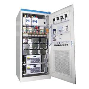
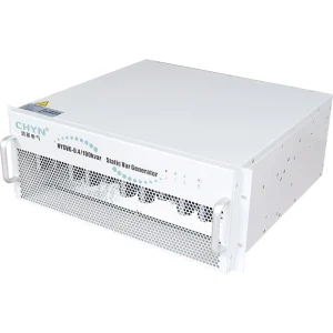
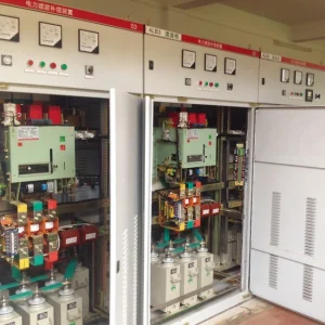
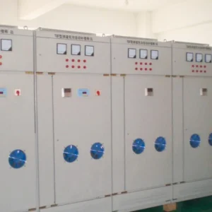
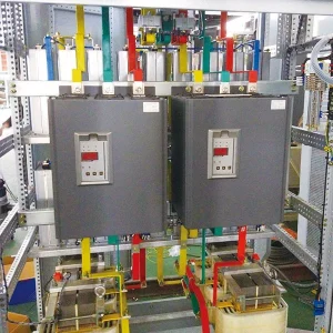
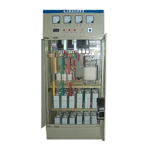
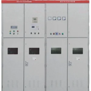
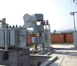
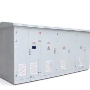
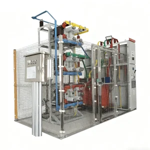
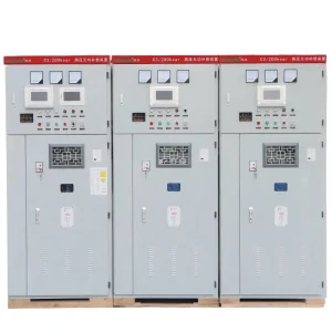
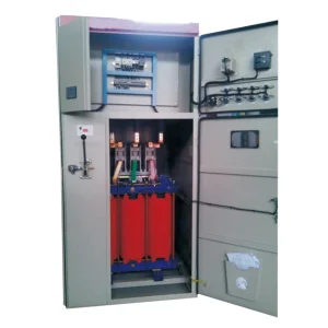
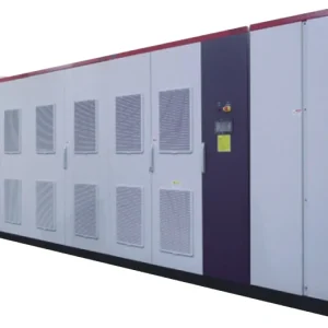
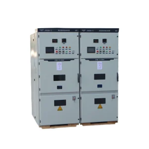
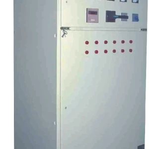
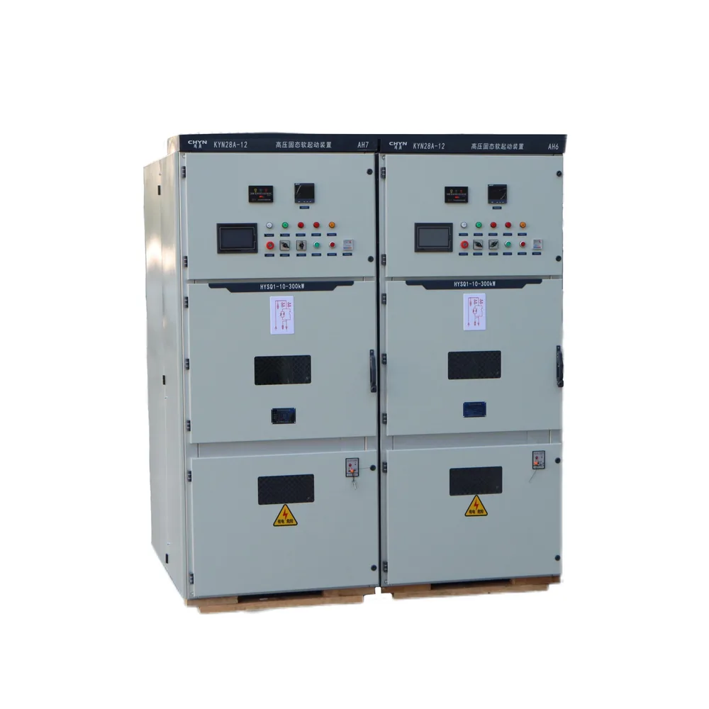
The CHYN HYSQ1 solid-state soft starter provides the relevant product family for this review. Its public product information does not establish an approved maximum outgoing cable length for every installation. Request an application review for the exact voltage, motor, cable construction and control configuration. Any model-specific restrictions should appear in the supplied documentation. Do not interpret an adjustable starting-time range as permission to keep a stalled motor energized for that entire range.
Separate permanent design decisions from adjustable commissioning settings. Conductor size, cable construction, protection arrangement and starter selection should be resolved before attempting site tuning. Initial voltage and current limit cannot compensate for every weakness in the supply circuit. Record the approved adjustment boundaries and the conditions requiring engineering review. A commissioning technician should not need to discover a cable compatibility limit through repeated unsuccessful starts.
Check voltage at the motor during acceleration
The motor terminal voltage depends on the source, starter output and voltage lost through the circuit. Review both starting and normal-running conditions. Starting current, power factor and speed change during acceleration, so a steady-state full-load voltage-drop calculation does not describe the complete event. Use a motor-starting study where the application warrants it, with cable impedance and source information suitable for the installed system. Check the supply bus impact as well as the motor terminal condition.
The U.S. Department of Energy motor-system sourcebook includes voltage-drop surveys and examination of circuit connections as practical motor-system assessment tasks. For the present application, specify measurements that distinguish source weakness, cable drop and connection problems. Have qualified personnel plan safe measurement locations and suitable instruments. A reading at the starter input alone cannot demonstrate what occurred at a remote motor during the same start.
Compare synchronized voltage, current and speed evidence with the approved acceleration model. If the bus voltage falls significantly before the cable contribution is considered, increasing conductor size may address only part of the problem. If one phase behaves differently, investigate the complete circuit rather than assuming cable length is the cause. The separate article on motor-starting voltage drop discusses the broader supply issue; this review adds the specific outgoing-cable compatibility question.
Treat capacitance as a separate supplier question
Obtain cable capacitance data for the actual construction and length, including the supplier's definition of each value. Identify shielding, grounding arrangement and all parallel outgoing runs. Also list surge capacitors, power-factor capacitors and other devices connected on the starter output. Ask the starter manufacturer which capacitance quantities are relevant to its design and how the complete circuit must be assessed. A general cable brochure or a measurement with unspecified connections may not provide the necessary input.
Do not transfer VFD output-filter rules directly to a soft starter. Both applications involve power electronics, but their output waveforms and operating sequences differ. Equally, do not assume that a full-frequency motor supply makes cable capacitance irrelevant during semiconductor control. A supplier may require a specific study or approved arrangement. Any additional reactor, filter or protection device must form part of that reviewed design; it should not be added from a generic long-cable checklist.
Use a coordinated engineering review table
The following table identifies evidence to request. It intentionally supplies no universal cable-length, capacitance or voltage-drop limit. Acceptance values must come from the applicable design rules, motor requirements and starter documentation. Record each value's origin and revision so that later route changes can be evaluated consistently.
| Review item | Required information | Approval question |
|---|---|---|
| Cable route | Actual length, construction, joints and parallel runs | Does the approved arrangement match the installed route? |
| Voltage during starting | Source impedance, starting study and synchronized records | Is sufficient accelerating capability available? |
| Output capacitance | Cable data and all connected output devices | Is the total arrangement compatible with this starter? |
| Thermal duty | Acceleration time, current profile and hot restart requirement | Are motor, cable and starter duties acceptable? |
| Protection and testing | Settings, isolation boundaries and approved test procedure | Can faults be cleared and insulation tested safely? |
For background on the interaction between motor behavior and a trailing cable, the NIOSH-hosted motor and cable analysis provides a research example. It concerns its own modeled system, not a validation of the proposed CHYN installation. Its useful implication here is to retain the cable and supply in the engineering model instead of evaluating the motor as though its terminal voltage were fixed.
Coordinate protection, bypass and test boundaries
Review ground-fault protection with the cable type, grounding system and motor arrangement. Ensure the selected instrument locations and settings reflect the circuit being protected. If leakage, unbalance or a trip occurs, preserve the event record before changing settings. A longer cable is a reason to investigate the electrical model, not a reason to weaken protection. Record how the starter transitions to bypass and confirm that protection remains effective in both controlled starting and normal running.
Before insulation testing, follow the equipment manufacturer's instructions for disconnecting sensitive electronics and defining the test boundary. The approved method must address the starter, motor, cable, surge devices and instrument connections. Do not apply an insulation-test voltage through power-electronic equipment merely because the motor feeder appears isolated upstream. Establish discharge, grounding and restoration steps through the site's electrical safety procedure. All such work requires qualified personnel and equipment appropriate to the installation.
Plan a witnessed start with meaningful stop conditions
Agree the test load and initial thermal condition before the first attempt. Capture the source and motor voltages, phase currents, acceleration evidence, starter state and relevant protection indications on a common timeline. Define stop conditions from the approved motor and starter limits. If acceleration stalls or a protective function operates, stop, preserve the data and investigate. Repeating the same attempt can consume the permitted thermal duty without providing additional information.
Change one approved variable at a time and record why the change is justified. Review current limit and acceleration together: reducing current may reduce available torque and lengthen the event. Extending the ramp may increase thermal exposure if the motor is not accelerating as expected. Compare the result with the soft-starter acceleration-time assessment and the motor thermal-protection review. These are complementary checks rather than independent settings to optimize in isolation.
Observe the bypass transition and the subsequent running condition. Record whether voltage and current stabilize as expected and whether the motor reaches its required operating point. If stopping control is part of the purchase requirement, review that sequence separately with the driven process. Passing a start does not prove that a soft stop will avoid every hydraulic or mechanical transient. Keep process acceptance criteria distinct from the electrical evidence.
Submit a complete enquiry and preserve the approved baseline
Send the supplier the motor nameplate and performance curves, load information, supply study, single-line diagram, cable data sheets, route length, parallel-run details and connected output devices. Include environmental conditions, altitude, starting frequency, hot restart expectations and the intended protection scheme. Request explicit confirmation of compatibility and a list of assumptions. If the route later becomes longer, or the cable construction changes, revisit the review before installation rather than assuming the earlier approval remains valid.
At handover, preserve the final route schedule, settings, configuration backups, acceptance records and any manufacturer conditions. Link each recorded start to its initial temperature, load state and settings revision. Identify who can approve future changes. This evidence helps distinguish a later cable fault or deteriorating connection from an application problem that existed at commissioning. It also gives the maintenance team a practical reference when replacement equipment is considered.
Educational background: induction-motor starting
This NPTEL IIT Kharagpur lecture introduces three-phase induction-motor starting. It helps explain why starting conditions deserve separate evaluation from normal running. It does not approve cable lengths, demonstrate HYSQ1 settings or replace the manufacturer's installation instructions.

Watch the educational lecture on YouTube.
Frequently asked questions
What is the maximum motor cable length for a soft starter?
There is no universal value for every starter and cable. Request approval for the actual voltage, construction, route length, parallel runs, motor duty and output-connected devices using the supplied starter documentation.
Will increasing the starting voltage solve a long-cable problem?
It may change acceleration, but it does not establish cable compatibility or eliminate source and protection constraints. Evaluate synchronized measurements and the approved model before making a permitted adjustment.
Can a VFD output filter be used automatically?
No. A soft starter has a different operating waveform and sequence. Any added output equipment needs explicit approval as part of the complete starter, cable and motor arrangement.
What records are most useful after an unsuccessful start?
Save synchronized source and motor voltages, phase currents, acceleration evidence, control states, protection events, settings and initial thermal conditions. Stop within the approved limits and review those records before another attempt.