
 Zhejiang Hongyan Electric Co., Ltd.
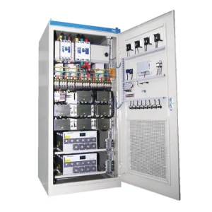
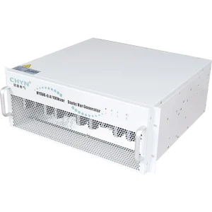
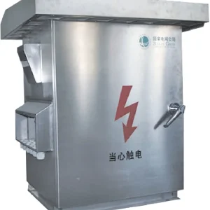
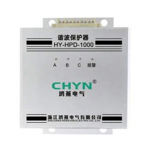
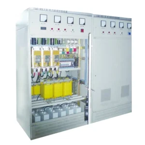
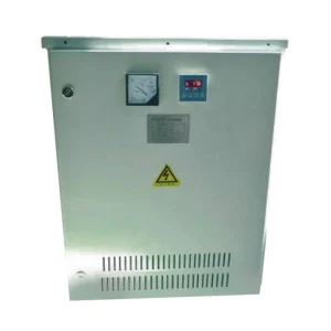
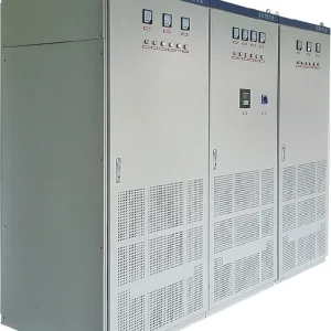
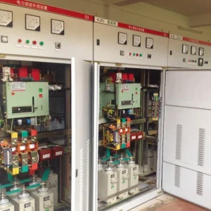
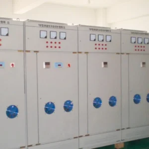
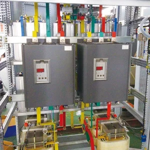
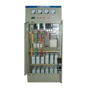
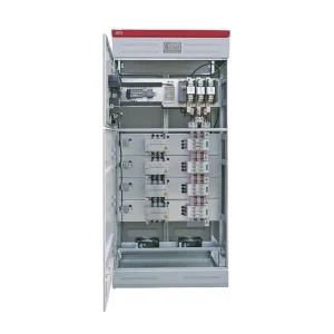
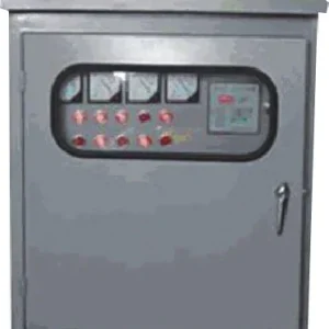
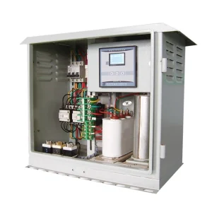
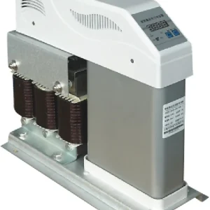
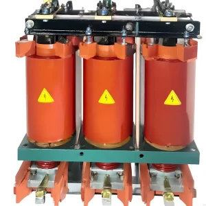
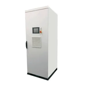
Static var generator parallel operation requires a supported control arrangement, a clearly defined measurement boundary and verified sharing between the available modules. Adding cabinet ratings does not establish usable compensation capacity. Before accepting an expanded system, confirm how demand is measured, how each unit receives its command and what happens when one unit stops. This guide focuses on preparing a site acceptance record for multiple SVG units on a common bus. It does not provide wiring instructions or assume that different manufacturers, firmware versions or communication interfaces are interchangeable.
Start with the bus and the control objective
Draw the complete electrical boundary before comparing unit displays. Mark the incoming feeder, bus coupler, compensation branches, capacitor steps, generator connection and all loads included in the target. Identify the point at which power factor or signed reactive power must meet the project requirement. A controller measuring one feeder cannot automatically represent a second feeder behind an open coupler. Include normal and alternate switching states in the review rather than treating the single-line diagram as a permanently fixed circuit.
Define what the expanded installation must accomplish. Examples include supplying reactive demand during a production increase, preserving a specified reserve during maintenance or reducing leading reactive power after capacitor steps remain connected. Each objective requires its own observation period and operating conditions. Obtain approved acceptance criteria from the responsible engineer and supplier. Do not promise unity power factor under every condition or infer a required module count from a monthly utility bill alone.
Confirm that parallel capability applies to the supplied configuration
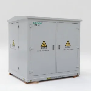
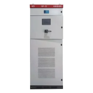
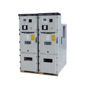
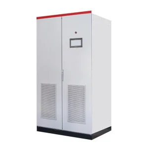
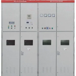
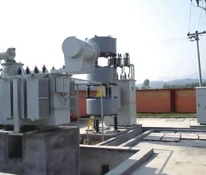
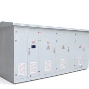
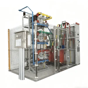
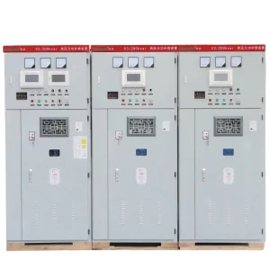
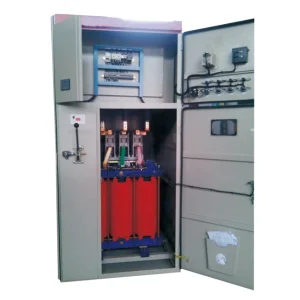
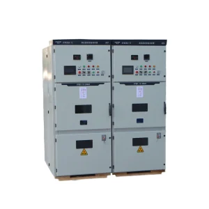
The CHYN HYSVG static var generator product page describes modular parallel expansion. That establishes product relevance, but the installation still needs an approved arrangement covering the actual units, controller version and interfaces. Request a configuration drawing showing the supported module combination, measurement inputs, control links, auxiliary supply and protective devices. A communication port listed for monitoring does not by itself prove that the port provides real-time sharing or synchronization.
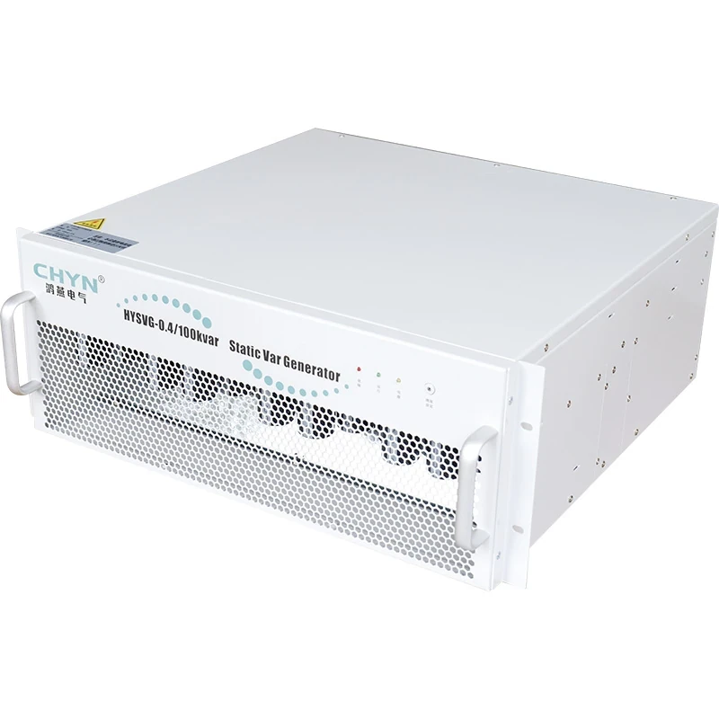
Record the model, firmware and configuration revision of every module. Ask whether equal-size and mixed-size modules can operate together, whether one controller allocates demand and whether another unit takes over following controller loss. Obtain the defined behavior when the communication link fails. These answers belong in the purchase specification and commissioning procedure. They should not be filled in from another supplier's manual, even when the cabinet appearance and terminal names seem similar.
Keep measurement boundaries consistent
For each CT input, identify its physical location, phase association, polarity, ratio and the current included in its measurement. Distinguish load-side measurement from source-side residual measurement. The controller must interpret compensation branch current consistently with the selected arrangement. If one unit sees demand before compensation and another sees demand after compensation, the two readings may be individually plausible while serving different control objectives. Review the complete measurement chain rather than correcting a display by trial and error.
Do not prescribe generic CT secondary connections. Some systems distribute sampled information digitally; others require an explicitly documented instrument circuit. Burden, isolation, test facilities and input compatibility must match the approved design. Work on instrument circuits requires qualified personnel and the applicable isolation procedure. For measurement-chain background, see the separate guide to SVG CT polarity planning. Parallel expansion adds the further task of proving that every participating controller refers to the intended common boundary.
Specify a test matrix before energization
The following qualitative matrix is a suggested project review tool, not a standard with universal limits. Agree the permitted deviation, settling behavior and response to failures before testing. Use synchronized records at the common bus and each compensation branch. Save the command and availability state together with measured output, so that a limited unit is not mistakenly classified as a sharing fault.
| Operating condition | Record together | Question to resolve |
|---|---|---|
| One module available | Bus kvar, module current, command and limit flags | Does one unit respond in the required direction? |
| All modules available | Individual output, approved allocations and total response | Does sharing follow the supported allocation rule? |
| Small demand | Signed bus kvar, enable states and switching events | Does control remain stable near its target? |
| One module unavailable | Availability flags, remaining headroom and bus deviation | Is the specified reduced-capacity behavior achieved? |
| Changed bus topology | Coupler position, measurement boundary and active controller | Is the correct control zone selected? |
Keep the electrical operating point comparable when evaluating two runs. A change in load, bus voltage or capacitor status can explain a change in module output without indicating a malfunction. Include the instruments' time basis, averaging window and measurement location in the record. Screenshots taken several minutes apart are inadequate evidence for diagnosing a short interaction between controllers.
Evaluate sharing against the approved allocation rule
Equal branch current is appropriate only when equal sharing is actually intended and the units have comparable available capacity. Mixed ratings, thermal derating, maintenance reserves and compensation priorities can justify unequal output. Ask the supplier to state whether allocation follows installed rating, available current or a different rule. Compare measured reactive contribution with that rule at the same voltage and operating point. Total current magnitude alone can include components that do not represent the intended reactive service.
A simple planning illustration shows why this matters. Suppose two units have approved available reactive allocations of 60 kvar and 40 kvar at the test condition. A total request of 50 kvar would split into 30 kvar and 20 kvar under a proportional allocation rule: 50 × 60/100 and 50 × 40/100. These invented inputs illustrate arithmetic only; they are not CHYN ratings or a recommended sharing tolerance. The actual controller may use another documented strategy, and its current limits must be evaluated separately.
Research on parallel converters illustrates why electrical connection alone does not prove stable sharing. A national-laboratory evaluation of multiple grid-forming inverters identifies reactive sharing and control compatibility as system-level issues. Those grid-forming experiments are background, not a wiring or tuning prescription for a grid-connected SVG. Use them to frame questions about the complete installation. They do not establish which coordination method the supplied HYSVG implements, its supported module count, its communication protocol or its response to any particular outage.
Include outages, restart and capacitor coordination
Capacity expansion and redundancy are separate requirements. A system with several modules may still depend on a shared controller, auxiliary supply or measurement circuit. Define the service that must remain after a unit becomes unavailable. Confirm the approved test method and any loads that must be protected before simulating failure. Observe whether the remaining modules accept additional demand within their limits, whether the system reports reduced availability and whether a stopped unit rejoins without an unacceptable disturbance.
Where fixed or switched capacitors share the bus, record their state during every test. Their contribution may change the SVG demand, especially near low load. Coordinate targets and switching delays through the approved design rather than assigning multiple controllers competing responsibility for the same target. The SVG light-load guide addresses signed reactive power near small demand, while the SVG sizing guide covers capacity planning. The parallel-operation record should show how those requirements remain satisfied as availability changes.
Prepare evidence for expansion and handover
Provide the supplier with the single-line diagram, load records, required target, existing compensation details, available fault information and intended expansion stages. Include cable routes, environmental conditions and physical access for maintenance. Ask for the approved maximum configuration, future compatibility conditions, spare strategy and acceptance procedure. Obtain an explicit list of tests that may be performed on site and those requiring factory support. Avoid creating outage tests that expose operating loads to an unassessed loss of compensation.
At handover, retain configuration backups, measurement drawings, settings, firmware identifiers and synchronized test files. Assign ownership for updating the record when a unit is replaced. A replacement carrying the same nominal rating may still require a compatibility review. Log the reason for any unequal sharing that was accepted and the operating conditions under which it is permitted. This makes the next maintenance visit a comparison against a known baseline instead of another attempt to interpret unrelated display photographs.
Educational background: reactive compensation
The following NPTEL IIT Guwahati lecture explains the reactive-power concepts behind the bus target. It does not demonstrate CHYN parallel wiring or commissioning. For additional university background on shunt compensation, consult the NPTEL discussion of reactive-power control devices; its SVC example should not be confused with the installed SVG topology.

Watch the educational lecture on YouTube.
Frequently asked questions
Can different SVG brands be connected in parallel?
Connection to one bus does not prove control compatibility. Obtain a system-level design and written confirmation covering measurement, coordination, protection and operating limits for the exact combination before approving it.
Should every module show the same current?
Only if equal sharing is the approved objective under comparable available capacity. Mixed ratings, thermal limits or reserved capacity can justify different outputs. Compare the relevant reactive contribution against the documented allocation.
Does installing extra modules guarantee redundancy?
No. Common controllers, measurement circuits, auxiliary supplies and upstream protection may remain shared dependencies. Define the required reduced-capacity service and demonstrate it through an approved outage and restoration test.
What should be checked after replacing one unit?
Verify compatibility, configuration, measurement association, communication identity, protective settings and the supported restart sequence. Repeat the relevant sharing and failure-response checks, then update the baseline and handover documents.