
 Zhejiang Hongyan Electric Co., Ltd.
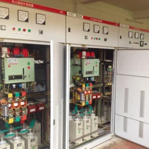
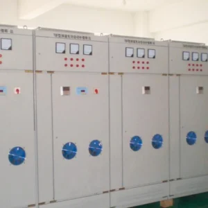
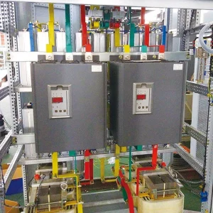
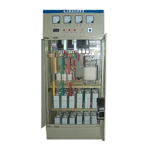
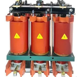
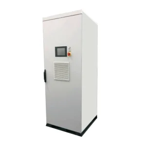
Active harmonic filter current limiting means the converter has reached an allowed output boundary and cannot supply every requested compensation component. Residual distortion can therefore remain even while the filter is operating. Diagnose the condition by comparing synchronized load, supply and filter currents with the actual enabled modes, available modules and operating limits. A high distortion percentage alone does not establish insufficient capacity. First prove that the measurement boundary and settings are correct; then distinguish a genuine current ceiling from thermal reduction, missing modules, a measurement error or an upstream voltage problem.
For the underlying compensation principle, see how an active harmonic filter works. The investigation here concerns residual distortion when an operating boundary is reached.
Define the operating condition before changing settings
Start with the event that prompted the investigation. Was a maximum-output indication present continuously, only during a production transition, or after several hours of operation? Record the affected feeder, running machines, capacitor steps and supply arrangement. Include whether the facility was on its normal transformer or an alternative source. A screenshot taken after the process returns to normal may contain no evidence of the original condition.
Keep current limiting separate from a protective trip. A converter may reduce its output, remain at a configured ceiling, or stop, depending on its design and the triggering condition. Obtain the installed model's alarm definitions and firmware instructions. Do not assume that a different supplier's description of continuous operation at full current describes a CHYN unit or establishes permission to operate through an alarm.
The research overview on active-filter dimensioning and control explains current injection as a controlled tracking task with internal energy dynamics. It supports examining both command and actual response. It does not provide the alarm thresholds, thermal curves or commissioning settings for the installed equipment.
Capture three current records on the same timeline
The useful comparison is between the nonlinear load demand, the converter contribution and the remaining supply current. Label each instrument channel with its physical location and direction. A feeder measurement downstream of a branch junction cannot automatically represent the current at the contractual point of evaluation. Keep the single-line drawing beside the records so that a later reviewer can reconstruct the measurement boundary.
Record phase RMS current, fundamental current, relevant individual harmonic currents and voltage distortion during the same operating interval. Include filter output current and the controller's capacity indication where available. Use compatible aggregation intervals when comparing records. Short peaks in one logger and minute averages in another can make a healthy controller appear to ignore a load change.
Distortion percentages require their denominators. A lightly loaded feeder can show a large THDi while carrying modest harmonic amperes. Conversely, a lower percentage during heavy production can represent a larger compensation duty. For the measurement definitions and their different purposes, review THD versus TDD before deciding which result demonstrates a problem.
Use the symptom to choose the next investigation
The following table is a diagnostic worksheet, not a set of universal alarm limits. Compare every observation against the installed equipment documentation and the agreed site measurement method. None of these rows authorizes bypassing protection or increasing a current setting above its approved value.
| Observed pattern | Evidence to collect | Next question |
|---|---|---|
| Output plateaus as production demand rises | Per-phase output current, command or capacity indication, simultaneous load spectrum | Has a documented current boundary been reached? |
| Available output falls as the cabinet warms | Temperature trend, fan status, inlet condition, thermal alarm history | Is cooling or environmental duty reducing available output? |
| One module contributes little or nothing | Individual module status, communications and current contribution | Is the installed capacity actually available? |
| Large residual distortion without a capacity indication | CT ratio, phase mapping, selected orders and evaluation location | Is the filter measuring and targeting the intended current? |
| Supply voltage distortion changes independently | Bus voltage spectrum and adjacent feeder operating states | Does the problem extend beyond this compensated load? |
Check how compensation modes share the available output
Some active-filter configurations address harmonic current together with reactive current or phase imbalance. Check which functions the purchased configuration supports, which are enabled, and how priority is assigned. A project requiring harmonic mitigation should not quietly lose its intended margin because an unrelated mode was enabled during an earlier service visit. Save the original settings before making an approved change.
Do not add percentage indicators from separate screens as though they were independent spare capacity. Their definitions may differ, and some represent commands rather than measured output. Ask the manufacturer how the controller allocates its current budget and whether per-phase or neutral constraints can become binding first. The answer should reference the installed topology and software revision.
The US Department of Energy power-factor guidance describes reactive power and capacitor correction. Use it to understand that reactive demand is a separate engineering quantity; it is not an active-filter current-allocation manual. A good investigation documents the requested reactive function rather than assuming that every available ampere is dedicated to harmonics.
Distinguish unavailable capacity from undersizing
Count operating modules, not cabinet spaces. A cabinet may contain a disconnected module, a disabled control channel or equipment awaiting repair. Compare the equipment register, purchase documents and current status display. If one module is unavailable, establish why before concluding that the original design was too small. Restoring supported operation and adding capacity are different corrective actions.
Review cooling without opening energized enclosures. Blocked air paths, an abnormal room condition or a failed fan may require an authorized outage and service work. Temperature trends should identify where each sensor is located. A normal room thermometer does not establish an acceptable internal semiconductor temperature. Never disable thermal reduction to obtain a more attractive harmonic measurement.
Measurement faults can also imitate a capacity issue. Confirm CT identity, ratio, phase association and controller configuration against the approved drawing. For a separate examination of waveform distortion in the sensors, see active harmonic filter CT saturation. Treat any work on current-transformer circuits as qualified electrical work under the site's approved procedure.
Run a staged verification with explicit stopping conditions
Prepare a test plan with operations personnel before changing production. Choose stable operating states that already occur in normal service, then record the transition between them. Define who can stop the trial and what alarms require stopping. Do not deliberately overload a converter or create a network disturbance to make a current-limit indication appear.
Compare a baseline state with a higher-demand state while keeping the supply arrangement and evaluation point consistent. If an approved mode change is part of the investigation, change one item at a time and save both configurations. Check that improved harmonic results have not produced an unacceptable reactive-power result or a new neutral-current concern elsewhere.
Judge the result over the intended duty cycle. A short successful snapshot does not establish performance during a long hot production run. Equally, one brief transition should not be generalized into continuous inadequacy. State the tested load range, ambient conditions and available modules beside the conclusion. Leave untested combinations explicitly open for later verification.
Prepare the service or expansion decision
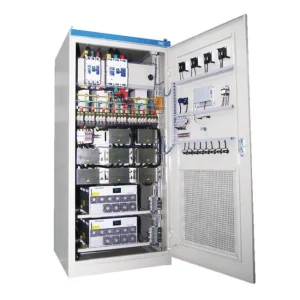
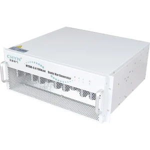
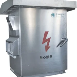
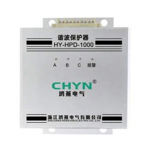
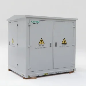
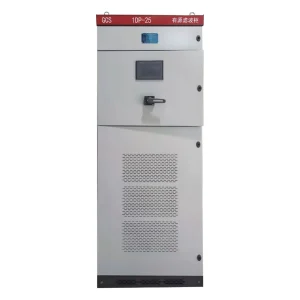
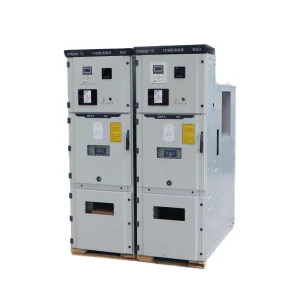
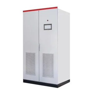
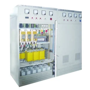
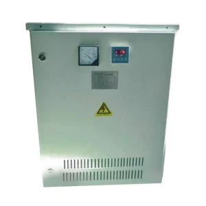
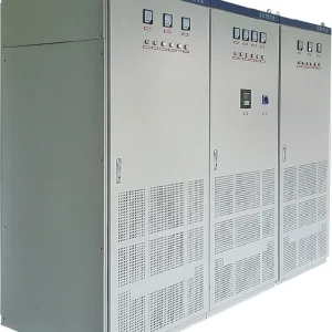
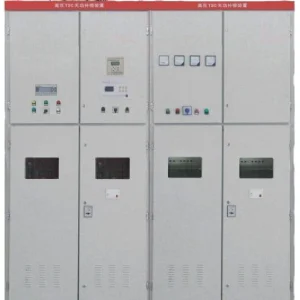
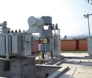
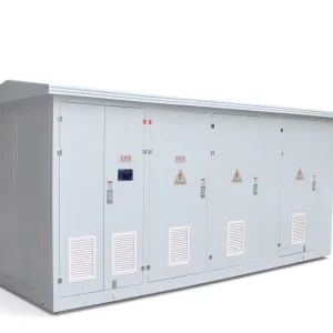
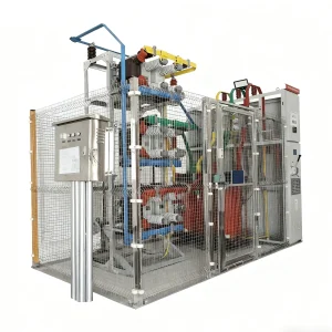
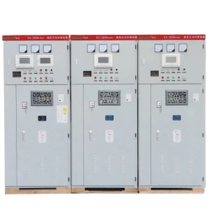
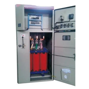
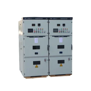
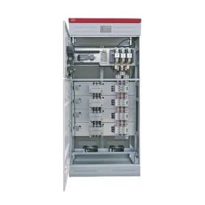
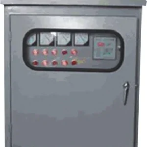
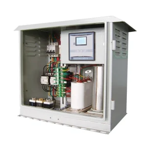
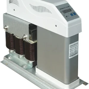
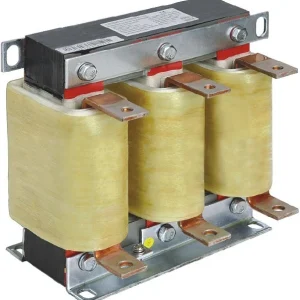
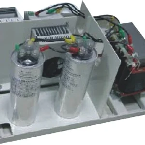
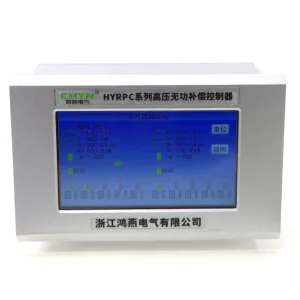
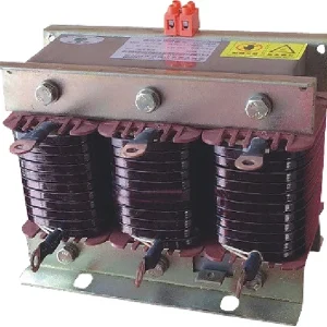
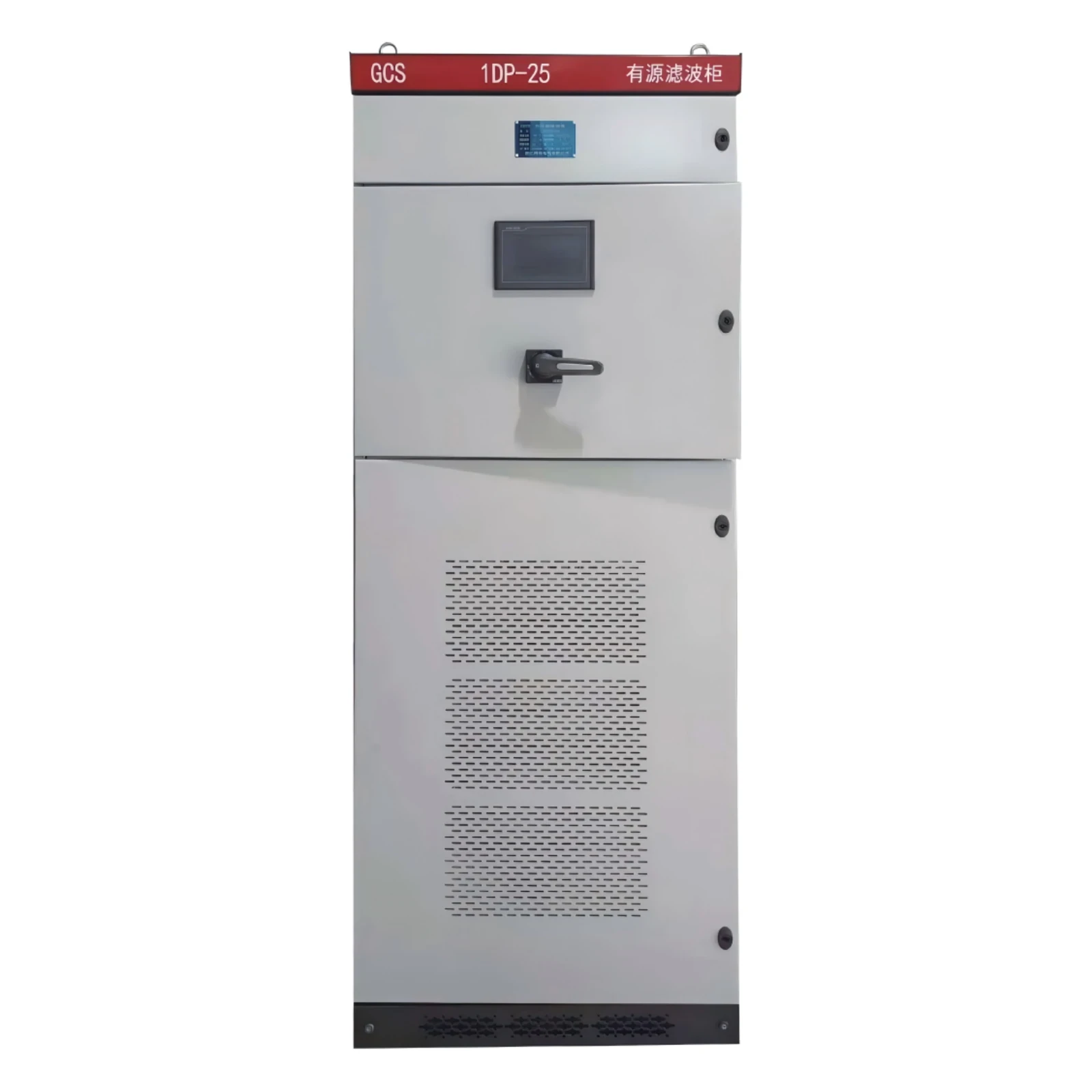
Send a concise evidence package with the CHYN active power filter inquiry: single-line drawing, module inventory, current records, harmonic spectra, supply voltage, event history and a settings export. Confirm the product URL and installed configuration with the equipment documents; a product photograph identifies the equipment family, not its available output at this site.
The decision should identify whether to correct measurement, restore a module, repair cooling, revise approved priorities or evaluate additional capacity. For expansion, ask how new modules will share measurement signals, coordinate control and affect protection and space requirements. Require a revised acceptance plan rather than assuming that another cabinet automatically resolves the original performance complaint.
Educational background: how shunt compensation works
This IIT Delhi lecture introduces shunt active power filters and helps explain why the injected current and the remaining supply waveform must be considered together. It is background education, not a substitute for the installed unit's operating instructions or the site's approved test procedure.
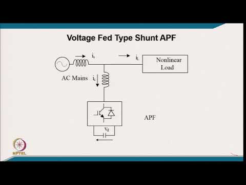
Watch the educational lecture on YouTube.
Frequently asked questions
Does a current-limit indication prove that the filter is faulty?
No. It indicates a boundary defined by the particular controller, but its meaning must be checked in the model documentation. Compare the requested compensation, actual output and available modules. A fault, a configured ceiling and a genuine demand above available output require different responses.
Should the current limit simply be increased?
Only an approved setting within the manufacturer's documented operating envelope should be considered. First establish why the present boundary is reached. Raising a setting cannot restore a failed module, repair cooling or correct an inaccurate measurement, and it must never defeat protection.
Why can distortion remain while the filter runs?
Possible causes include a finite output budget, selected harmonic orders, measurement boundaries, unavailable modules or network voltage distortion. The investigation should separate these possibilities using synchronized records rather than judging the equipment from one percentage on a display.
What evidence should accompany a capacity review?
Provide representative load states, phase and neutral currents where relevant, harmonic amperes, voltage spectra, filter output, mode priorities and module availability. Include the evaluation location and monitoring interval so that the proposed remedy can be tested against the same duty.