
 Zhejiang Hongyan Electric Co., Ltd.
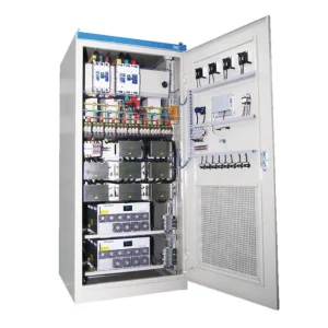
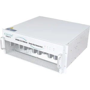
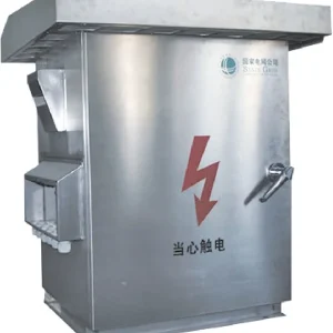
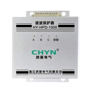
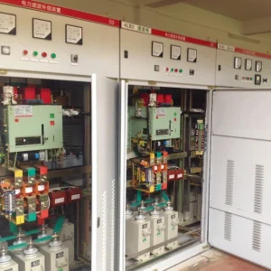
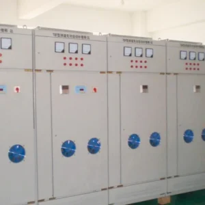
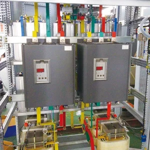
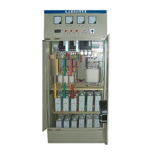
Soft starter motor thermal protection must match the motor's permitted heating during starting, running and cooling. Reducing starting current does not automatically make a long start thermally safe, and protecting the starter's power semiconductors does not necessarily protect the motor windings. Before selecting settings, obtain the motor's hot and cold thermal limits, the measured acceleration profile and the actual protection arrangement. Then check that current measurement, thermal memory, temperature sensors and the trip path remain effective through bypass operation. Repeated thermal trips require investigation; increasing a trip class simply to finish a start can remove an essential safeguard.
Separate motor heating from starter overheating
A high-voltage soft starter and its motor contain different heat-producing components. Thyristors, cooling passages and cabinet fans determine part of the starter's thermal condition. The motor has stator windings, rotor conductors, bearings and its own ventilation arrangement. A cabinet temperature alarm cannot establish that the rotor is within its permitted starting duty, while a motor overload model does not prove that the starter's heatsink is adequately cooled.
The Natural Resources Canada motor guide distinguishes several protective functions and explains electronic overload estimation and thermal memory. Apply that distinction when reviewing a quotation: ask which device measures each condition, which device makes the trip decision, and which switching device actually removes power.
Use the medium-voltage soft starter and VFD comparison for the broader equipment choice. This thermal review addresses a narrower issue: whether the selected motor and starter can safely complete their specified duty, including a restart when the motor is already warm.
Collect the motor data that a nameplate cannot supply
The nameplate provides essential ratings, but it rarely defines the complete starting thermal envelope. Request the manufacturer's cold and hot damage curves, permissible locked-rotor times, starting-current information and approved duty cycle. Establish the meaning of hot and cold for that specific motor. A motor that has been stopped briefly is not necessarily in a cold condition.
Obtain the driven-load torque-speed curve and total referred inertia. A fan, pump or conveyor can produce very different acceleration and cooling behavior even at the same rated motor power. Include the real process state at restart: a loaded conveyor or a pressurized compressor may require a different torque profile from an unloaded commissioning test.
Record ambient temperature, altitude, enclosure, cooling method and any separate ventilation. Identify winding and bearing sensors, their exact types and the trip equipment that accepts them. Sensor readings and a current-derived model complement one another; neither should be assumed to cover every internal hot spot without the motor supplier's assessment.
Compare acceleration with thermal limits
A reduced-voltage start changes both current and available torque. If torque becomes too low for the driven load, acceleration can lengthen or stall. Lower current sustained for much longer can still produce substantial heating. Consequently, a current-limit value should be assessed together with acceleration time and the motor's thermal envelope.
As a simple screening illustration, compare two hypothetical current histories using the integral of squared current over time. A constant three times rated current for twenty seconds gives 180 rated-current-squared seconds. Four times rated current for eight seconds gives 128 in the same normalized units. These calculations demonstrate why lower current alone does not establish lower accumulated heating.
The illustration is not a motor protection model or a safe-starting limit. Real currents vary during acceleration, winding resistance changes with temperature, and rotor losses depend on slip and machine design. Use recorded current-versus-time traces and the manufacturer's approved method for the actual assessment. Do not substitute a simplified stator heating estimate for a rotor thermal-limit curve.
When a start approaches the permitted envelope, investigate the torque margin, supply voltage, load condition and starter selection. The separate soft starter acceleration-time guide helps organize that investigation. Extending the allowable trip delay without resolving the limiting condition can turn a commissioning problem into motor damage.
Check every part of the protection chain
| Protection element | Question to resolve | Evidence required |
|---|---|---|
| Current-derived overload model | Does it use the correct motor rating and thermal data? | Settings file, CT ratios and selected hot/cold characteristics |
| Winding temperature input | Are the sensor and input compatible? | Motor sensor schedule, input documentation and simulated alarm/trip test |
| Stall or excessive-start protection | Will a failed acceleration clear before motor damage? | Approved coordination study and measured acceleration record |
| Thermal memory and cooling | What happens during stop and loss of control power? | Device-specific manual and controlled functional test |
| Bypass operation | Does the motor remain measured and protected? | As-built circuit diagram and running-mode trip verification |
| Final trip circuit | Does the intended switching device remove supply? | End-to-end test record, including feedback and restart inhibition |
The table is a verification checklist, not a list of functions guaranteed in every starter. The Virtual Labs induction-motor protection experiment identifies thermal overload, single phasing, earth fault and locked rotor as separate concerns. The ordered installation needs an explicit allocation of these duties rather than a general statement that protection is built in.
Verify protection during bypass and shutdown
Many installations transfer running current to a bypass path after acceleration. Check whether the motor-protection CTs still measure the full motor current in that state. A sensor positioned only in a semiconductor branch may no longer provide the signal expected by a separate protective function. Establish this from the approved diagram and device manual, not from the presence of a bypass contactor alone.
Also check the trip destination. Blocking thyristor triggering is not sufficient if another closed path continues feeding the motor. The approved protection scheme must open the relevant switching device and confirm the expected state. Coordination with upstream fault protection requires a qualified protection study, including the interrupting capability of the selected equipment.
During shutdown, the motor may cool more slowly after its shaft-mounted fan stops. The protection device's cooling model and treatment of lost control power vary by design. Ask whether thermal state is retained, how elapsed off-time is handled and what conditions permit a new start. A power cycle must not become an informal way to bypass a legitimate restart restriction.
Investigate a trip before changing the trip class
Start with the event log and identify which function operated. Thermal overload, locked rotor, excessive starting time, sensor fault and starter overtemperature can produce similar production interruptions but require different corrective work. Preserve the first event and preceding current record before clearing alarms or changing parameters.
Check all phase currents, actual supply voltage, the mechanical load and the cooling condition. Compare the current-transformer settings with the installed hardware and motor rating. Determine whether the motor was warm from normal operation or repeated attempts. Then inspect the relationship between the selected protection curve and the motor's permitted hot-start envelope.
A higher trip class is acceptable only when the motor data, starter capability and coordination assessment support it. A normal first start followed by an unsuccessful immediate restart can indicate inadequate recovery time, a changed process load or incorrect thermal handling. Treating every trip as nuisance operation removes the evidence needed to distinguish those causes.
Specify acceptance evidence with the starter order
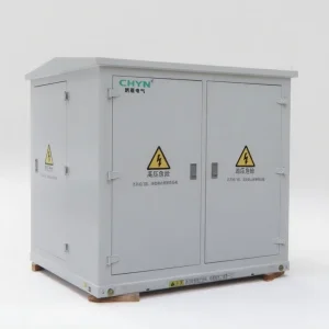
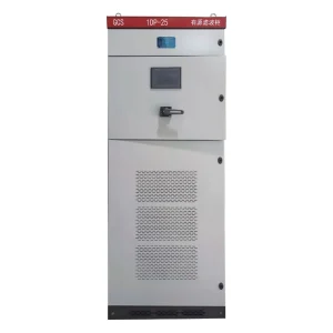
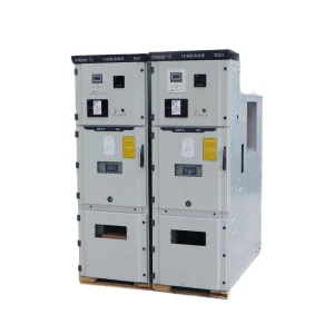
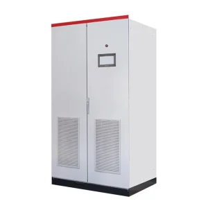
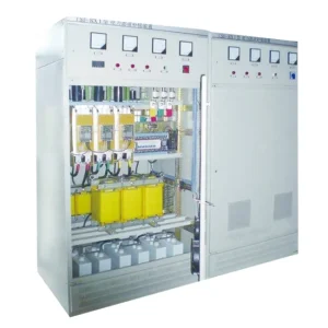
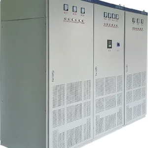
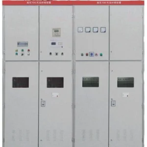
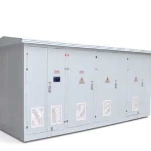
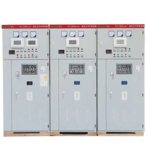
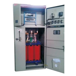
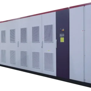
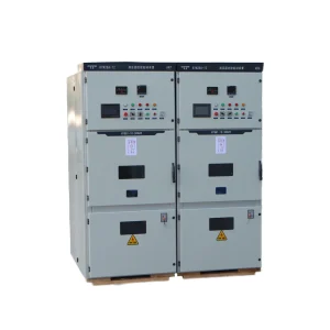
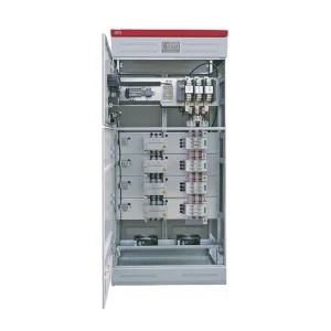
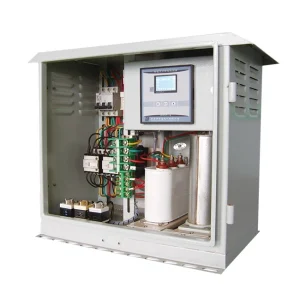
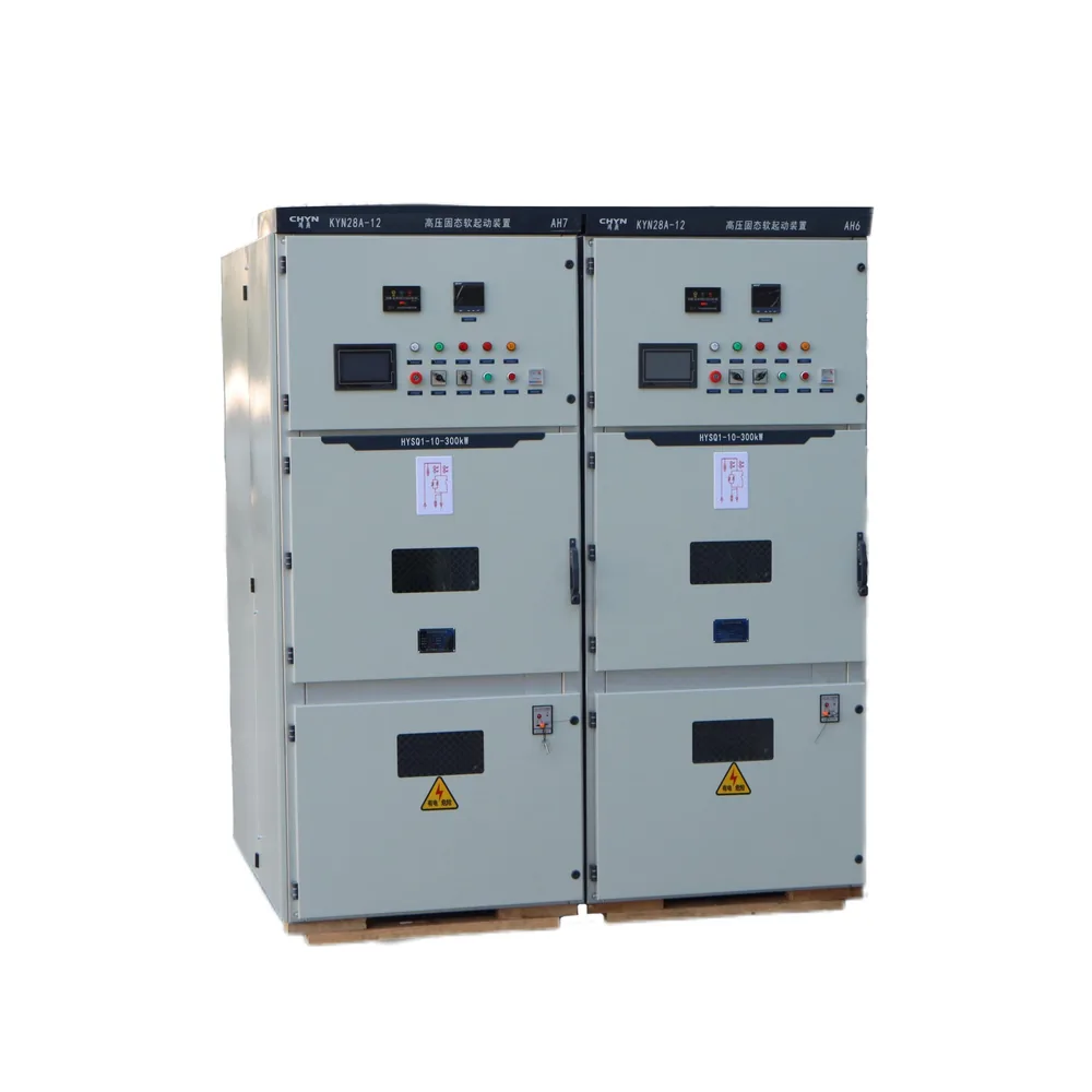
The CHYN HYSQ1 high-voltage solid-state soft starter page lists overload and other protective functions. Request confirmation of the exact ordered configuration, external relay responsibilities, available motor-temperature inputs and documented starting duty. The product photograph and general feature list do not establish a particular motor's thermal compatibility.
Agree on factory functional tests and site acceptance tests before shipment. Secondary injection or approved input simulation can verify relay logic, alarms and trip circuits without deliberately overheating a motor. Any live start test must follow the motor manufacturer's duty limits and the site's approved procedure. Destructive or repeated stalled starts are not an acceptable substitute for protection testing.
At handover, retain the motor curves, final settings, wiring drawings, CT details and time-stamped start traces. Record the conditions under which the warm restart was evaluated, including cooling interval and process load. Clearly identify any condition assessed by calculation rather than tested on site so operators understand the actual acceptance boundary.
Use the starts-per-hour duty review alongside the thermal assessment when repeated process cycles are required. The permitted sequence must satisfy both motor and starter limits.
Learn how motor protection functions work together
The following university lecture introduces digital induction-motor protection. It provides background for understanding the protection scheme; it is not a programming tutorial for a CHYN starter and does not replace the ordered equipment manuals.

Watch the educational lecture on YouTube.
Frequently asked questions
Does a soft starter automatically protect the motor from overheating?
Only the documented, correctly configured protection arrangement can establish that coverage. Starter temperature monitoring, motor overload estimation and winding-temperature inputs serve different purposes and must be checked separately.
Can a lower starting current still cause a thermal trip?
Yes. If reduced torque greatly extends acceleration, accumulated heating can remain excessive. Evaluate the complete current-time trace, motor thermal curves and driven-load requirements together.
Should a hot motor use the same allowable start time as a cold motor?
Do not assume that. A warm motor has less remaining thermal margin. Use the motor manufacturer's hot and cold limits and the protection device's documented thermal-state treatment.
What should be checked after a bypass change?
Confirm that the protection still measures motor current, receives temperature inputs and opens the correct power path. Verify trip feedback and restart blocking through an approved functional test.