
 Zhejiang Hongyan Electric Co., Ltd.
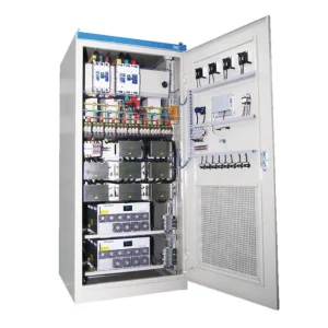
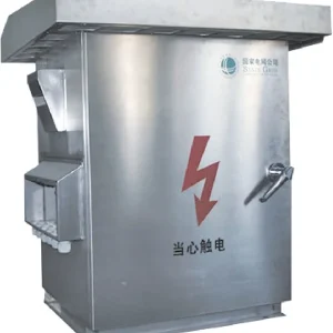
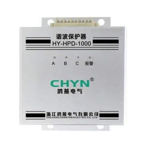
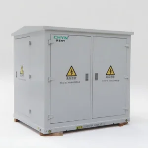
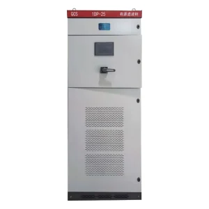
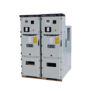
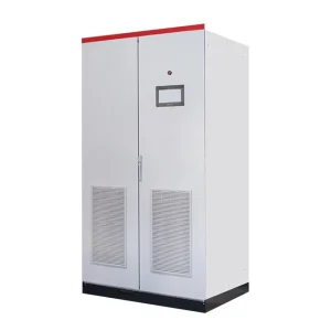
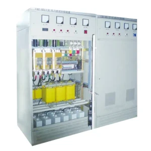
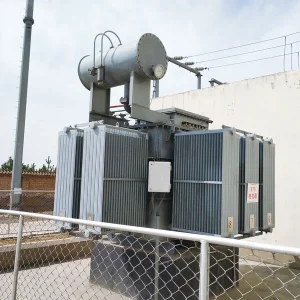
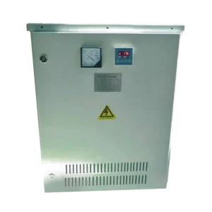
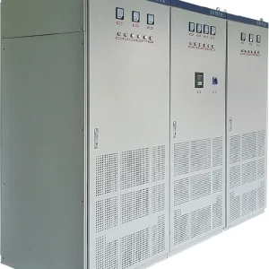
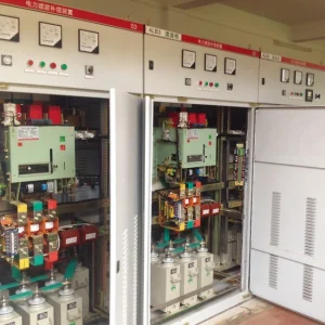
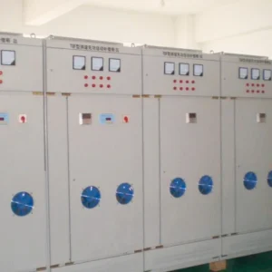
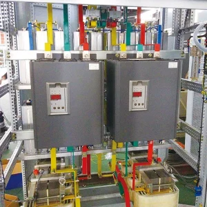
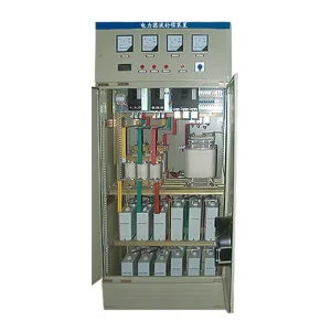
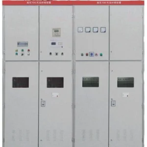
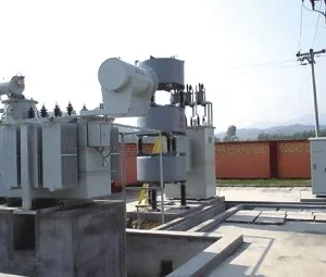
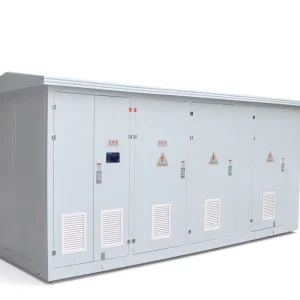
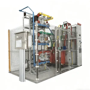
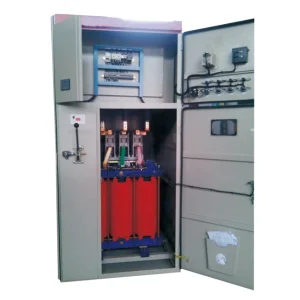
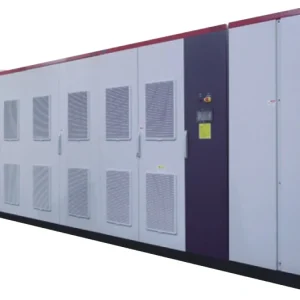
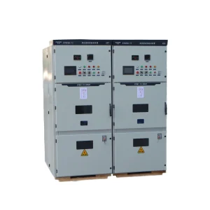
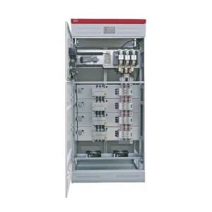
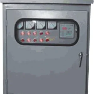
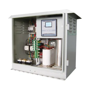
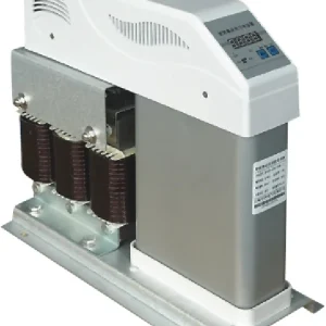
A static var generator at light load should follow the site's signed reactive-power demand, rather than chase a power-factor display that becomes unstable when real power is very small. Before changing settings, establish the meter convention, the measurement boundary and which capacitor stages remain connected overnight. Then verify that the SVG can supply the required inductive or capacitive current within its documented operating range. A successful adjustment keeps reactive exchange and voltage within the agreed limits across shutdown, standby and restart conditions. It does not require a perfect power-factor number during every near-zero-load interval.
Why an acceptable daytime setting can fail overnight
A factory can have a good daytime power factor while exporting capacitive reactive power after production stops. Motors and process equipment leave service, but fixed capacitors, cable charging and some filter branches may remain. The net reactive demand changes in magnitude and can reverse direction. Increasing compensation merely because the displayed power factor is low can therefore move the operating point farther from the intended target.
The US Department of Energy explanation of power-factor costs establishes the relationship between real power, reactive power and apparent power. For an operating review, keep these quantities separate. Low power factor alone does not identify whether the required correction is capacitive or inductive, nor does it prove that additional equipment capacity is necessary.
Also distinguish true power factor from displacement power factor. Harmonics can reduce the former even when fundamental reactive power is already close to the target. An SVG configuration intended for fundamental reactive correction should not be assumed to eliminate distortion. Check the actual controller functions and the independent meter before interpreting the remaining difference as a control failure.
Define the measurement boundary before the target
Draw the incoming feeder, transformer, compensation connection, existing capacitors and major standby loads on one diagram. Mark where the current transformers and voltage reference obtain their signals. A feeder meter and an SVG display can both be working correctly while reporting different boundaries. Transformer magnetizing demand or a separate capacitor branch may appear in only one measurement.
Record the meter's sign conventions explicitly. A positive or negative kvar indication is meaningful only with the configured import/export and inductive/capacitive convention. Compare a known operating change with the diagram and meter documentation. Qualified personnel should verify polarity and phase association using the approved commissioning procedure; do not reverse secondary wiring experimentally on an energized current-transformer circuit.
Use the existing SVG current-transformer polarity guide for the measurement-chain investigation. Once measurement is trustworthy, this article's separate task is to define stable low-load behavior. Treating those two investigations separately prevents a misleading controller adjustment from concealing a wiring or boundary error.
Use signed kvar to understand a low-power example
For a balanced, approximately sinusoidal illustrative case, displacement power factor is P divided by the square root of P squared plus Q squared. Here P is real power in kW and Q is fundamental reactive power in kvar. The magnitude does not indicate the direction of Q, so retain the signed reactive reading alongside the calculated power factor.
Suppose a standby load consumes 5 kW and imports 2 kvar inductively. The apparent power is approximately 5.39 kVA and displacement power factor is 0.928 lagging. If the load then falls to 0.5 kW with the same 2 kvar demand, apparent power becomes approximately 2.06 kVA and displacement power factor falls to 0.243. The reactive demand did not increase tenfold; the denominator relationship changed.
These are teaching values, not proposed acceptance limits or CHYN performance claims. With distorted waveforms, use the instrument's measured true power factor and documented fundamental quantities instead of this simplified relationship. Near zero real power, an apparently large power-factor movement may correspond to a small reactive change within the measurement system's uncertainty.
Separate the operating cases in the control review
| Observed condition | Evidence to collect | Decision to review |
|---|---|---|
| Production stops and reactive export appears | Signed incoming kvar and capacitor-stage status | Remove unnecessary capacitive contribution before demanding continuous absorption |
| Power factor oscillates near zero kW | Meter resolution, kvar trend and low-current behavior | Use documented low-load logic and an agreed reactive-power tolerance |
| SVG and incoming meter disagree | CT boundary, phase association and sign convention | Resolve measurement differences before changing the target |
| Converter repeatedly reaches its current limit | Command, actual output, voltage and enabled duties | Check available capacity in the required direction |
| Capacitor stages repeatedly switch | Stage command timestamps and SVG output trend | Coordinate separate controllers rather than accelerating both |
This decision table describes an engineering investigation, not universal controller settings. The Natural Resources Canada motor reference guide discusses matching capacitor operation to load and the effects of operating conditions. The appropriate SVG settings still depend on the selected equipment documentation and the site's connection requirements.
Coordinate capacitors before increasing SVG duty
An SVG can absorb inductive reactive current only within its specified capability. That does not make leaving unnecessary capacitor stages energized a good design decision. The converter may spend the entire shutdown interval counteracting a fixed contribution, using current capacity and producing losses without delivering useful correction for an operating process.
Review which stages can be disconnected when their associated load stops. Include any passive filter branches: disconnecting these may change harmonic conditions, so the decision needs a system study rather than a simple power-factor rule. Assign responsibility for each switching command and document how the SVG and capacitor controller interact during stage changes.
For mixed equipment, consult the separate hybrid compensation coordination discussion. Its wider control arrangement complements the low-load cases here. Record how delays, deadbands and enable conditions prevent two controllers from repeatedly correcting each other's response. Do not copy another installation's numerical settings without testing the actual system.
Specify low-load behavior when requesting equipment
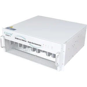
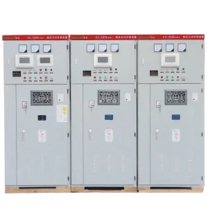
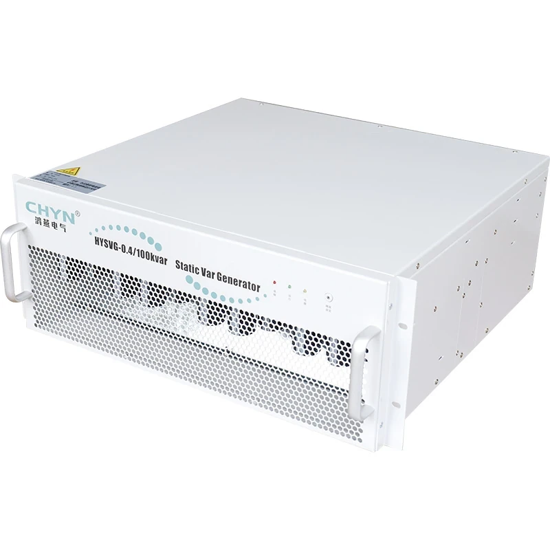
The CHYN HYSVG static var generator product page describes continuous compensation with inductive and capacitive reactive current. For a purchase specification, ask for the selected configuration's supported modes, measurement requirements, low-current accuracy and current capability in each direction. A general product description is not a substitute for the ordered unit's setting manual or guaranteed operating envelope.
Provide daytime and overnight measurements rather than only transformer capacity. Include minimum real power, signed reactive-power extremes, harmonic measurements, bus voltage, source changes, ambient conditions and any planned expansion. Identify whether the utility evaluates an instantaneous value, an interval average or reactive energy in separate quadrants. That distinction changes what the acceptance record must demonstrate.
Ask how the controller handles a near-zero signal, sensor failure, loss of communications and restoration of power. If standby, minimum-current thresholds or alternative control modes are offered, have their exact availability and behavior confirmed in writing. This avoids assuming that a feature found in another manufacturer's manual exists on the quoted CHYN unit.
Test shutdown and restart as one sequence
Capture a baseline during normal production, then the approved transition to standby, the settled overnight state and the restart. Log real power, signed reactive power, voltage, SVG output, current limiting and capacitor-stage commands on a common time base. Keep the independent meter settings and the source configuration unchanged throughout each comparison.
Agree on the permitted steady-state reactive band and any allowed transition interval before testing. Where measurement uncertainty dominates, record the uncertainty and use a defensible tolerance rather than claiming exact unity power factor. Do not force repeated large-load switching solely to create a dramatic demonstration; the test sequence must remain within the site's approved operating plan.
Review every limit event and unexplained command reversal. If the outcome changes between utility and generator supply, assess those modes separately with the generator supplier. Retain the final parameter file and a plain-language explanation of why each setting changed so later maintenance does not undo a deliberate low-load arrangement.
For the equipment principle, the static var generator overview explains the parent topic. Keep that principle separate from the acceptance decision: the site still needs a documented target, a trustworthy measurement boundary and evidence from its own operating sequence.
Learn the reactive-power background
The following IIT Guwahati lecture explains reactive-power compensation concepts. It supports understanding of the quantities used above; it does not provide settings for a CHYN controller or certify the performance of a specific installation.

Watch the educational lecture on YouTube.
Frequently asked questions
Should an SVG hold unity power factor at nearly zero load?
Use the agreed connection requirements and measurement capability. Near zero real power, signed kvar and voltage trends often provide a clearer engineering acceptance basis than a fluctuating power-factor number alone.
Can an SVG correct a leading power factor?
A configuration with sufficient inductive reactive-current capability may absorb the excess capacitive contribution. Confirm its operating envelope and first review unnecessary connected capacitors instead of assuming unlimited absorption.
Does low overnight power factor prove the SVG is undersized?
No. Check reactive-power direction, meter boundary, current-transformer signals, enabled control modes and actual current limiting. A low ratio caused by very small real power is different from a demonstrated lack of compensation capacity.
What records should accompany a low-load adjustment?
Keep the measurement diagram, sign convention, baseline trends, approved acceptance limits, final settings and shutdown/restart results. Include unresolved harmonic or generator conditions rather than treating a daytime reading as complete acceptance.