
 Zhejiang Hongyan Electric Co., Ltd.
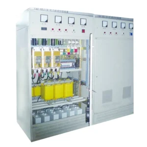
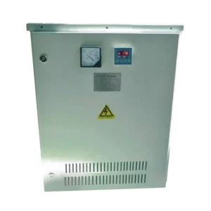
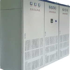
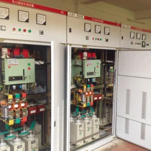
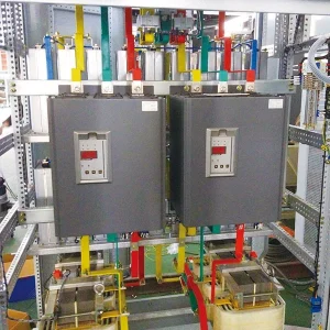
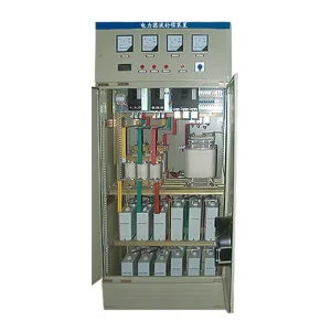
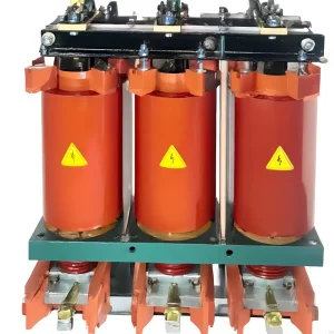
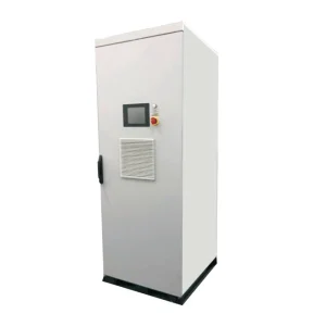
Active harmonic filter switching frequency describes how often the converter changes its semiconductor switching state. It helps determine current ripple, losses and practical current control, but it does not independently establish harmonic performance. Compare filters using the same load spectrum, measurement location, output current, ambient conditions and acceptance criteria. A higher advertised kHz value can be useful, yet a filter with unsuitable sensors, inadequate current capacity or poor thermal margins can still miss the project target. The purchasing decision should connect the frequency claim to repeatable measurements under the operating conditions that matter to the facility.
Which frequency does the quotation describe?
Ask the supplier to identify the quantity before comparing two numbers. Semiconductor switching frequency, control sampling frequency, harmonic extraction update rate and effective ripple frequency are different specifications. An interleaved or multilevel arrangement can produce an output waveform whose apparent ripple pattern does not equal the switching rate of each individual device. Quoting that output pattern as a device frequency makes an apparently simple comparison misleading.
Also establish whether the figure is fixed, nominal, average or maximum. A variable-frequency controller may operate differently through the mains cycle and with changing current demand. A maximum observed value does not describe continuous operation at rated output. Request the operating range and the conditions attached to it, including supply voltage and any thermal reduction strategy.
For the basic current-injection principle, start with how an active harmonic filter works. Frequency comparison becomes meaningful only after the measurement boundary and intended compensation duties are clear.
Separate harmonic orders from converter switching
A harmonic order refers to a multiple of the supply fundamental. For example, the fifth harmonic of a 50 Hz supply is 250 Hz; the fifth harmonic of a 60 Hz supply is 300 Hz. These values describe components to be compensated. They are not settings that tell the converter how often to switch. A claim of compensation through a particular harmonic order therefore needs its own performance evidence.
The filter must measure the relevant current, calculate a reference and reproduce that reference through its converter and coupling components. Delay, voltage headroom and the current-control response influence the result. Increasing switching frequency does not remove a wrong CT connection or a saturated measurement chain. Verify the sensors first when measured behavior differs substantially from the design prediction.
Do not infer compliance at every operating point from a demonstration with one rectifier load. A mixed industrial bus can include several converters, changing production recipes and existing capacitor branches. The acceptance spectrum should represent that bus, including the loads expected after the next expansion.
Understand the loss and ripple tradeoff
The converter designer balances switching activity against waveform quality and heat. More switching events can increase switching losses under otherwise comparable conditions. Output ripple also depends on topology, coupling inductance, DC voltage and modulation. Consequently, two filters with different circuit designs cannot be ranked by a single proportional rule.
A university study of shunt active filter efficiency and hysteresis control distinguishes conduction and switching losses and examines reducing switching activity within its particular control arrangement. Its result supports examining the complete control and thermal design; it does not establish a universal preferred frequency for commercial equipment.
Ask for total input losses at representative compensation currents, with the test configuration stated. Identify whether auxiliaries and cooling fans are included. A low-loss figure at light output is not interchangeable with the heat load at continuous compensation current. The enclosure designer needs the operating loss that the actual cabinet must remove.
Use a comparison sheet that exposes missing evidence
| Quotation item | Clarification to request | Useful acceptance evidence |
|---|---|---|
| Switching frequency | Per device or effective output; fixed or variable | Declared definition and operating conditions |
| Harmonic range | Selectable orders and simultaneous current demand | Before/after current spectrum at the agreed bus |
| Thermal capability | Continuous current at site ambient and installation | Stabilized temperatures and loss measurement |
| High-frequency behavior | Output filtering and measurement bandwidth | Separate ripple or conducted-emission assessment where required |
| Transient performance | Load step, measurement delay and settling definition | Synchronized waveforms with repeatable load changes |
This is a qualitative purchasing framework, not a standards limit table. Agree numeric pass criteria through the project specification and applicable requirements. The US Department of Energy power electronics progress report includes active-filter research discussing switching-frequency and loss choices in a specific DC-link application. That application differs from a facility shunt filter, so its numerical design results should not be transferred to this comparison sheet.
Keep current capacity in the comparison
Separate the speed question from the amount of compensation current required. A fast converter can still reach its current limit when several harmonic components and reactive duties are requested together. Review the allocation rules: which functions have priority, which components are reduced first, and how the controller reports saturation. Compare these rules against the facility's main objective.
Use the dedicated active harmonic filter current-limiting guide when the system meets its rating but leaves residual distortion. Adding switching frequency to a tender does not replace calculating the current requirement or allowing for future load growth.
Request records at low, normal and high production loading. These conditions help reveal whether a good result depends on unused converter capacity. Where modules share a bus, document the number operating during every test, rather than presenting a full-system result beside a single-module power rating.
Plan measurements that can answer the actual question
Use a measurement plan with named channels, instrument bandwidth, recording duration and sensor orientation. Low-order harmonic analysis and switching-ripple analysis may require different acquisition settings. A meter configured only for the specified low-order harmonics cannot demonstrate the absence of higher-frequency components. Conversely, a noisy oscilloscope trace without appropriate probes and grounding is poor evidence of unacceptable site emissions.
Record the filter enabled and disabled under comparable loads, where an approved operating procedure permits this comparison. Keep production state, transformer configuration and capacitor switching state in the test log. Otherwise a load change between recordings can be mistaken for a filter effect. Save the underlying readings as well as the final percentage calculation.
Do not open energized cabinets to inspect switching nodes for a purchasing comparison. Qualified personnel should select safe measurement locations and appropriately rated instruments under the site electrical-safety procedure. Supplier laboratory evidence may be the proper way to establish internal converter behavior.
Apply the comparison to a CHYN enquiry
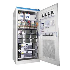
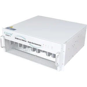
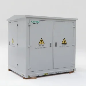
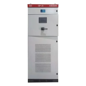
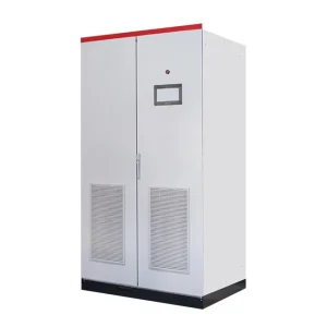
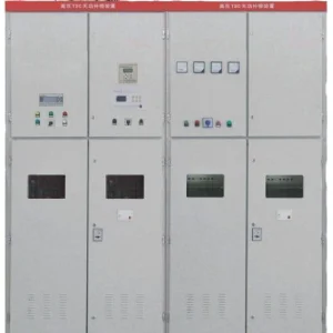
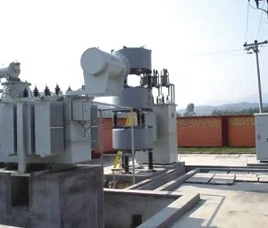
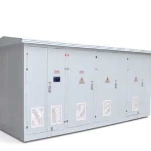
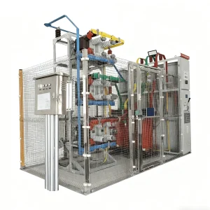
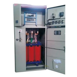
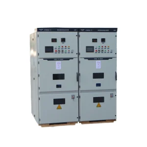
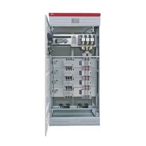
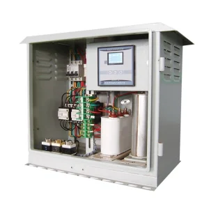
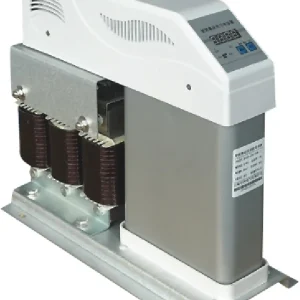
The CHYN HYAPF active power filter is the relevant product family for this discussion. Its product information describes a modular converter and switching-related features. Obtain a model-specific technical schedule for the proposed voltage, current and installation; do not turn a family-level statement into a guaranteed result for an unreviewed project.
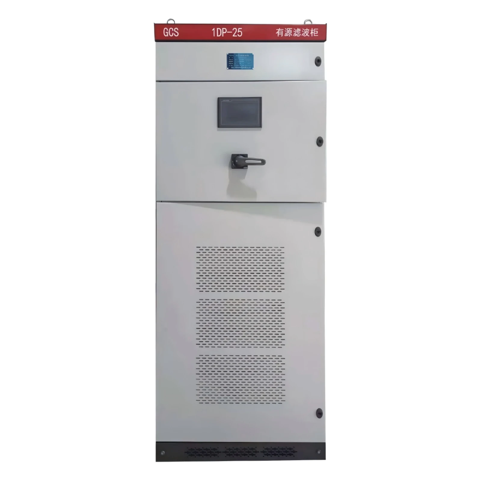
Send the supplier the single-line diagram, load list, recorded harmonic spectra, CT location, existing capacitor information and site ambient conditions. Ask for the declared frequency definition and the evidence supporting continuous operation at the proposed output. Include enclosure ventilation, access and maintenance restrictions so the offer reflects the final installation.
For the current requirement behind the enquiry, use the complementary active harmonic filter sizing workflow. Keep that capacity calculation separate from the frequency comparison, then combine both in the final technical evaluation.
Record acceptance and future changes
The acceptance report should identify the equipment model, firmware, approved settings, active module count and measurement files. Record deviations and the responsible party's resolution. If a supplier proposes a frequency or control change after testing, request its effect on losses, filtering and warranty before accepting the modification. A changed setting should trigger the relevant repeat measurements.
Keep the comparison sheet for later expansions. New drives or a changed transformer can alter the system conditions even if the filter hardware is untouched. Reusing the original benchmark makes the next investigation faster and prevents a nameplate kHz value from becoming the only remembered design criterion.
Specify how disagreements will be resolved before the order is placed. Name the measurement location, acceptable instruments and person responsible for reviewing abnormal results. Keep raw files available to both parties. A clearly defined comparison reduces the chance that different calculation windows or background load changes become a dispute about converter quality.
Educational background
The university lecture below explains shunt active power filters and their current-compensation role. Use it to understand the architecture before reviewing a supplier's implementation. It does not validate a particular switching frequency, model rating or site guarantee.
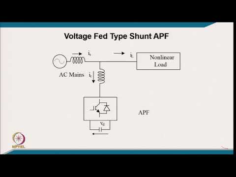
Watch the educational lecture on YouTube.
Frequently asked questions
Is a higher active harmonic filter switching frequency always better?
No. It must be assessed with current tracking, output filtering, losses, cooling and the required compensation duty. Compare measured performance under equivalent conditions instead of selecting the largest kHz number.
Is switching frequency the same as harmonic compensation range?
No. Harmonic range identifies supply-frequency multiples to be compensated. Switching frequency describes converter activity. The relationship depends on the complete converter and control design.
Can switching frequency be changed to fix poor site performance?
Only through a manufacturer-approved procedure with the relevant thermal and performance checks. First investigate measurement errors, current limits and system conditions rather than changing internal control settings.
What should buyers request alongside a frequency specification?
Request its definition, operating conditions, continuous current capability, losses, before/after spectra and an agreed acceptance method. Record the proposed model and installation details with those documents.