
 Zhejiang Hongyan Electric Co., Ltd.
Soft starter voltage unbalance should be investigated with simultaneous three-phase measurements and a record of the operating state. A current-imbalance alarm is not automatically proof that the starter is defective, and one acceptable average voltage does not establish a balanced supply. Compare all three incoming line voltages, phase currents and the event timeline before resetting or changing protection. Then determine whether the problem was already present upstream, appeared in the feeder, or coincided with a transition in the starting circuit.
This guide concerns diagnosing an unbalance complaint on a three-phase motor installation. It complements the wider comparison of medium-voltage soft starters and variable-frequency drives. The supplied starter, motor and protection instructions govern the actual installation.
Identify exactly what the alarm measured
Begin with the complete alarm text and its definition in the installed controller manual. Voltage unbalance, current unbalance, phase loss and negative-sequence protection describe related conditions, but their calculations and time delays need not be identical. Copying a threshold from another brand or another model can produce a misleading comparison even when the displayed percentages look similar.
Record whether the event occurred before acceleration, during the ramp, at bypass transfer or after sustained running. Include the starter topology and motor connection from the approved drawing. Measurements taken during controlled starting cannot be judged solely by the assumptions used for balanced sinusoidal running. The state is part of the evidence, not an optional note.
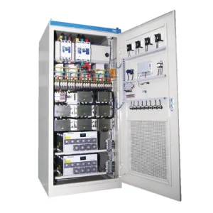
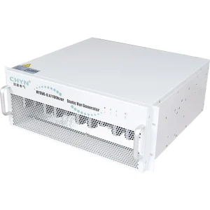
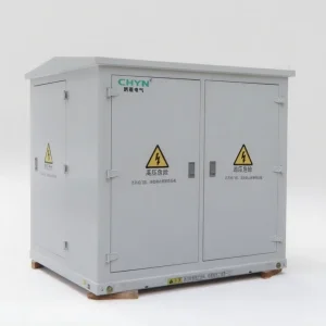
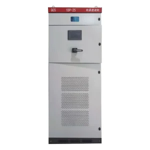
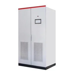
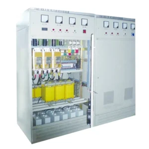
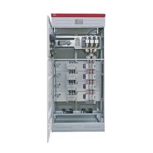
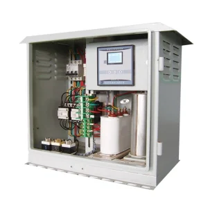
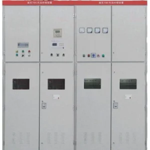
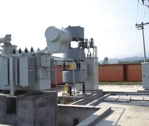
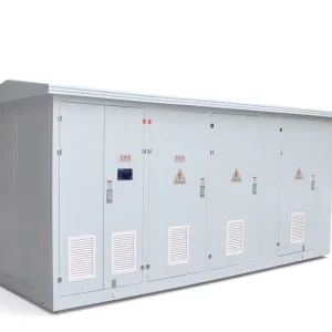
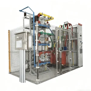
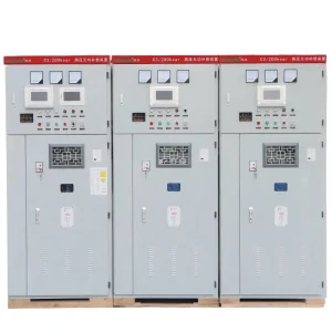
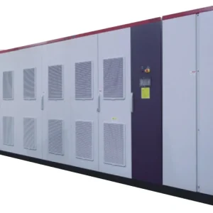
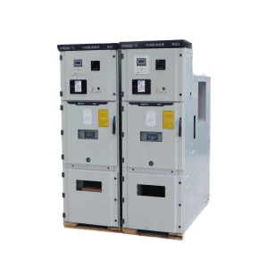
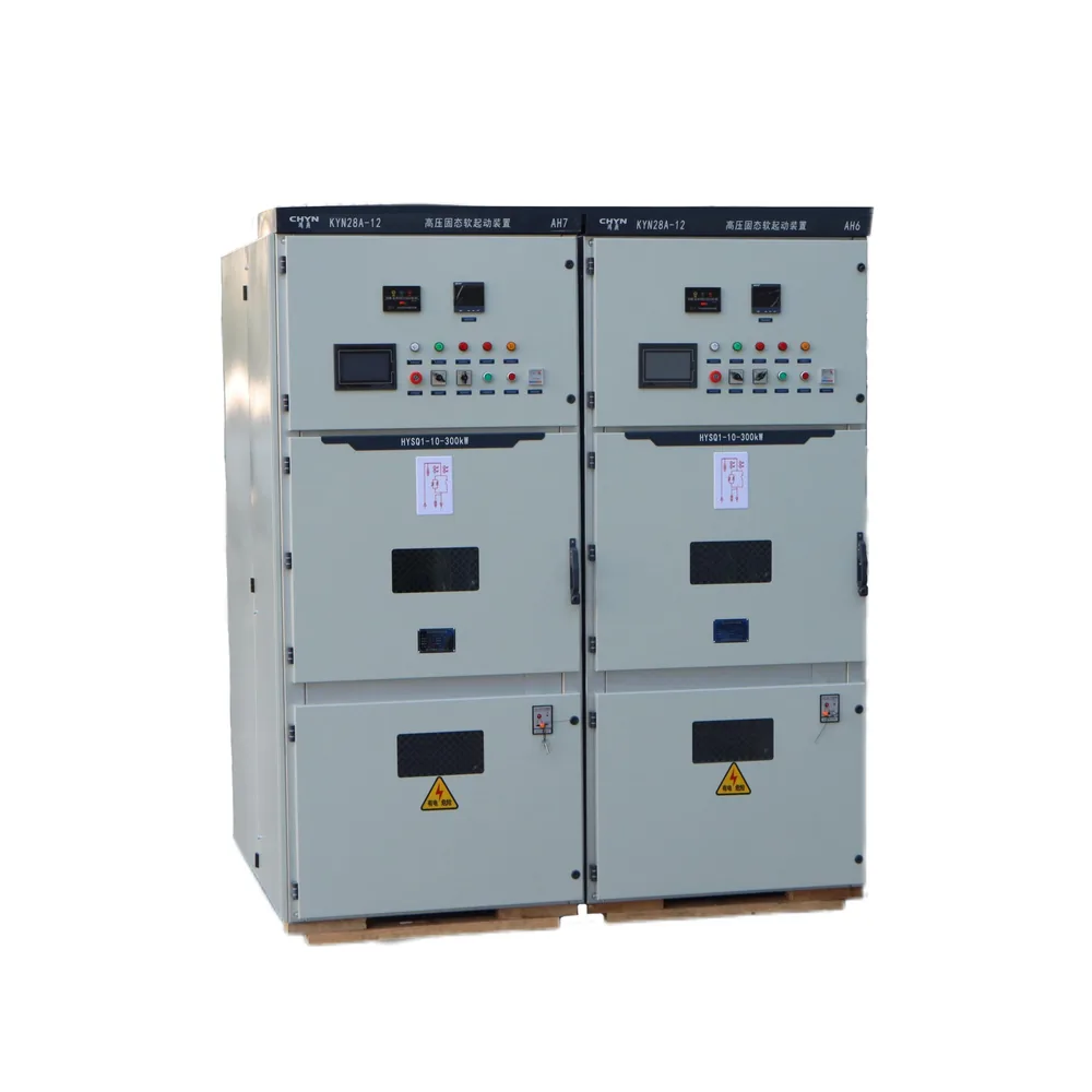
The CHYN HYSQ1 high-voltage solid-state soft starter page describes thyristor control and phase-loss protection. It does not publish every project's voltage-unbalance algorithm or trip setting. Request the installed protection schedule and exact model documentation before assigning an alarm threshold to it.
Calculate voltage unbalance with a stated method
One common voltage-magnitude screening method divides the maximum absolute deviation from the average of the three line-to-line voltages by that average, then multiplies by 100. Write both the three inputs and the result in the report. A percentage without its calculation method cannot be safely compared with a controller or analyzer that uses a different definition.
For an illustrative set of simultaneous readings of 400 V, 394 V and 406 V, the average is 400 V. The maximum deviation is 6 V, giving 1.5% by this method. The average voltage alone looks satisfactory, yet it hides the difference between phases. These are example numbers, not an operating acceptance limit or an instruction to continue running a motor.
The U.S. Department of Energy motor and drive sourcebook discusses voltage unbalance, motor heating and derating. Its guidance shows why small supply differences deserve attention. The motor manufacturer's applicable limits and the project's protection study still determine the permitted duty.
Where the specification uses negative-sequence voltage divided by positive-sequence voltage, obtain an instrument and dataset capable of reporting that quantity. Do not relabel the magnitude-deviation example as a sequence-component result. Similarly, a current-unbalance percentage cannot be substituted for voltage unbalance. The motor's response means the two percentages can differ substantially.
Compare the symptom with the operating state
| Observation | Investigation focus | Useful comparison |
|---|---|---|
| Incoming voltages differ before the start | Supply and distribution conditions | Same-time upstream bus and starter incoming records |
| Unbalance appears as starting current rises | Source stiffness and phase-path impedance | Incoming voltages and phase currents across the ramp |
| Symptom begins at bypass transfer | Transition state and approved power path | Contactor status, event timestamps and current waveforms |
| Running current differs despite similar incoming voltages | Downstream circuit, motor and measurement integrity | Phase-resolved running data with connection records |
| Display and independent recorder disagree | Sensing definitions and configuration | CT ratios, phase mapping, averaging windows and algorithm |
This table directs evidence collection; it does not diagnose a component from one symptom. The supply-to-motor relationship is consistent with the DOE sourcebook and Natural Resources Canada's electric-motor reference guide, which also discusses unbalance effects and the need for motor derating assessment.
Find the boundary where the problem first appears
Mark the utility or transformer bus, feeder protection, starter incoming terminals and motor circuit on the single-line diagram. Compare measurements made at the same operating point. If two instruments cannot be synchronized, state the limitation and avoid claiming that a changing load has been held constant. A short morning snapshot and an afternoon trip record are not a controlled comparison.
If the incoming supply is already unbalanced, investigate the supplying distribution system with the responsible electrical team. Uneven single-phase loading, abnormal connections and equipment conditions may need review. A motor starter cannot be assumed to correct an unsuitable upstream supply simply because it controls the motor's acceleration.
If the upstream record is comparatively stable but the symptom grows downstream under load, review the affected phase paths. Obtain isolated inspection results for fuses, terminations, cables and switching devices as appropriate to the installation. Do not identify a loose terminal solely from a voltage percentage, and do not tighten or disturb energized medium-voltage equipment as a diagnostic shortcut.
Preserve evidence from the starting and bypass sequence
Collect the start command, current-limit stage, acceleration completion and bypass indications where the installed arrangement provides them. Use the controller's actual state definitions. A generic run command can precede full acceleration, so it may be unsuitable as the boundary between starting and running measurements.
If the event coincides with transfer, give the equipment manufacturer the waveform and switching-state record. Establish whether the indicated bypass position agrees with the actual power path under the approved test procedure. Avoid repeated starts to reproduce the symptom until the permitted starting duty and motor thermal condition have been checked.
The separate guide to soft-starter bypass contactor coordination addresses the switching arrangement. Here the purpose of the transition record is narrower: to determine whether the unbalance existed before transfer or began with it. That distinction helps assign the next inspection without prematurely condemning the motor or starter.
Validate the measurement before adjusting protection
List each channel's physical phase, CT ratio, polarity and measurement range. Verify that the recorded values refer to the intended conductors and that the instruments are suitable for the voltage category, waveform and installation. A misidentified phase or incorrect scaling can turn a measurement problem into an apparent equipment fault.
Use phase-resolved data rather than total current or one combined power value. Keep the original waveform where available, together with the RMS calculation window. Note whether the instrument displayed fundamental quantities or total RMS quantities during the ramp. Comparing different quantities without that information can create a false disagreement.
All access and testing must follow the site's authorized electrical-safety process. Medium-voltage measurements need approved instrument transformers, connections and competent personnel. If intrusive tests are necessary, isolate the relevant equipment, verify the prescribed safe condition and follow the manufacturer's procedure. A soft-starter stop indication is not electrical isolation.
Connect the finding to motor heating and duty
Voltage unbalance can produce disproportionate current unbalance and additional heating. The consequence depends on the motor and operating condition, so a universal multiplier is inappropriate for a troubleshooting report. Record actual phase currents, loading, temperature information and the duration of the condition instead of estimating motor health from the supply average.
Separate the brief starting event from sustained running exposure. A motor may complete a start yet face an unacceptable running condition, or it may trip during acceleration while later readings look balanced. Review the full sequence against the motor's permitted duty. The absence of a trip after one reset does not establish an acceptable long-term operating condition.
Coordinate this review with motor thermal protection for soft-starter applications. Unbalance assessment and thermal protection answer different questions. A revised trip delay must not conceal a condition that the motor cannot tolerate, and a larger starter does not automatically resolve an upstream supply problem.
Prove the correction with a comparable record
After an approved repair or supply correction, repeat the measurements under a documented comparable load. Record the three line voltages, phase currents, starter states and motor loading, together with the revised drawing or maintenance reference. Use the same calculation definition as the original report so the comparison is meaningful.
Define success before the restart: stable operation through the intended sequence, measurements within the approved equipment limits, correct protection operation and no unresolved abnormal phase path. Include the person responsible for releasing the equipment. If production conditions prevent a representative test, record that limitation and keep the issue open for an agreed observation period.
For a supplier inquiry, provide nameplates, connection details, the alarm definition, settings revision and the pre/post records. Ask which additional measurement would distinguish the remaining causes. This is more effective than requesting replacement hardware based on one screenshot, and it leaves a clear basis for the next maintenance decision.
Further learning: motor starting behavior
This NPTEL IIT Delhi lecture explains induction-motor starting and speed control. It supplies background for interpreting the starting period; it does not define HYSQ1 fault codes or authorize energized diagnostic work.
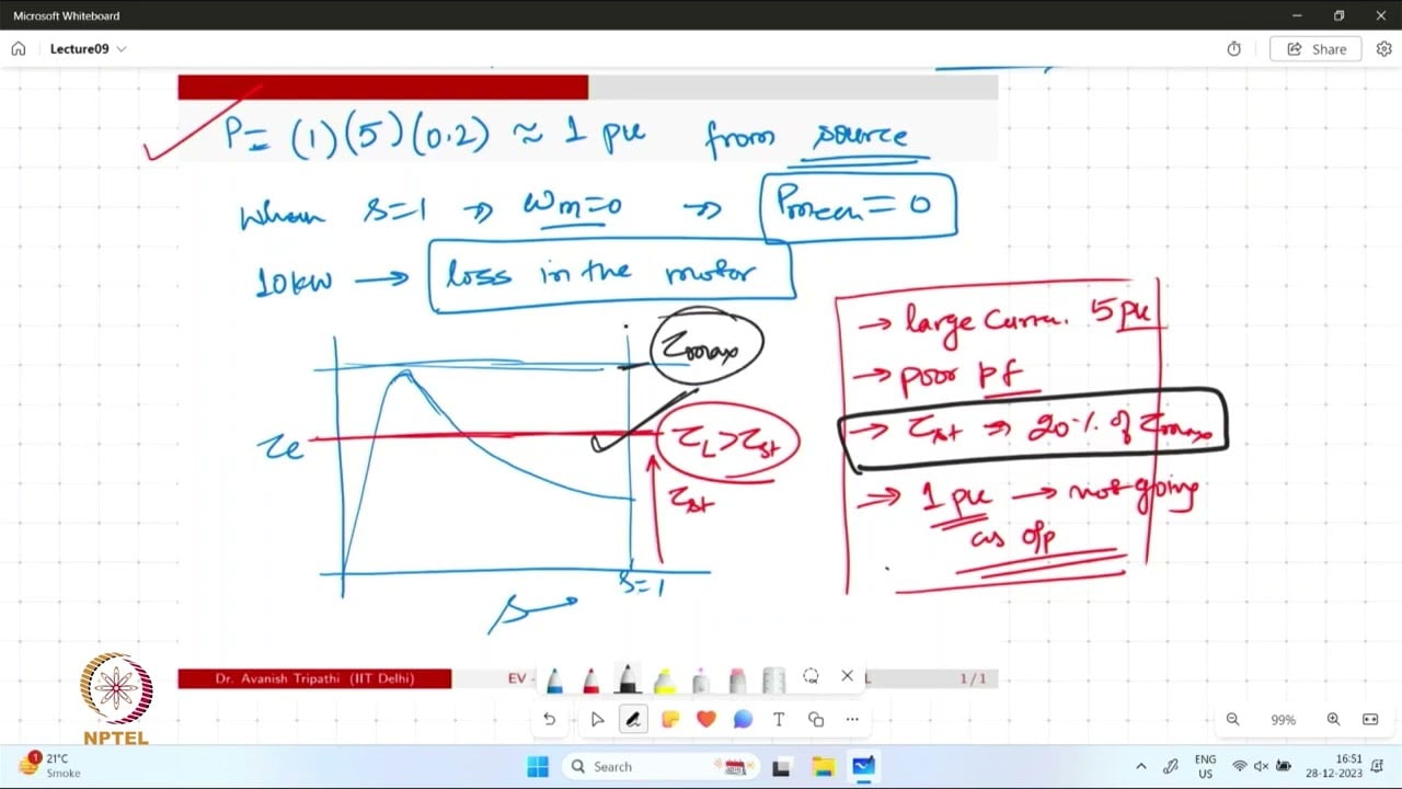
Watch the educational lecture on YouTube.
Frequently asked questions
Can an acceptable average voltage hide an unbalanced supply?
Yes. The average can be near nominal while individual line-to-line voltages differ. Retain all three simultaneous readings and state the calculation method.
Is current unbalance the same as voltage unbalance?
No. They are different quantities, and the motor response can amplify the current difference. Check the controller's actual alarm definition before comparing percentages.
Should the unbalance trip setting be increased first?
No. Validate the measurements and identify the electrical condition before revising protection. Any approved change must remain consistent with motor and starter capability.
Does an unbalance trip prove that the soft starter needs replacement?
No. Supply conditions, phase-path faults, motor issues and sensing errors can produce related symptoms. Use synchronized measurements and operating-state evidence to locate the problem.